
Related Manuals for Gigabyte G182-C20


Summary of Contents for Gigabyte G182-C20
- Page 1 G182-C20 AMD RyzenTM Threadripper Server System – 1U Gen3 NVMe User Manual Rev. 1.0...
- Page 2 GIGABYTE's prior written permission. Documentation Classifications In order to assist in the use of this product, GIGABYTE provides the following types of documentation: User Manual: detailed information & steps about the installation, configuration and use of this product (e.g.
- Page 3 Conventions The following conventions are used in this user's guide: NOTE! Gives bits and pieces of additional information related to the current topic. CAUTION! Gives precautionary measures to avoid possible hardware or software problems. WARNING! Alerts you to any damage that might result from doing or not doing specific actions.
- Page 4 Server Warnings and Cautions Before installing a server, be sure that you understand the following warnings and cautions. WARNING! To reduce the risk of electric shock or damage to the equipment: • Do not disable the power cord grounding plug. The grounding plug is an important safety feature.
- Page 5 Electrostatic Discharge (ESD) CAUTION! ESD CAN DAMAGE DRIVES, BOARDS, AND OTHER PARTS. WE RECOMMEND THAT YOU PERFORM ALL PROCEDURES AT AN ESD WORKSTATION. IF ONE IS NOT AVAILABLE, PROVIDE SOME ESD PROTECTION BY WEARING AN ANTI-STATIC WRIST STRAP AT- TACHED TO CHASSIS GROUND -- ANY UNPAINTED METAL SURFACE -- ON YOUR SERVER WHEN HANDLING PARTS.
- Page 6 CAUTION! Risk of explosion if battery is replaced incorrectly or with an incorrect type. Replace the battery only with the same or equivalent type recommended by the manufacturer. Dispose of used bat- teries according to the manufacturer’s instructions.
-
Page 7: Table Of Contents
Table of Contents Chapter 1 Hardware Installation ..................9 Installation Precautions ..................9 Product Specifications ..................10 System Block Diagram ................... 12 Chapter 2 System Appearance ..................13 Front View ...................... 13 Rear View ....................... 13 Front Panel LED and Buttons ................ 14 System LAN LEDs .................. - Page 8 5-2-4 Serial Port Console Redirection ................50 5-2-5 CPU Configuration ....................54 5-2-6 AMI Graphic Output Protocol Policy ...............55 5-2-7 PCI Subsystem Settings ..................56 5-2-8 USB Configuration ....................58 5-2-9 NVMe Configuration ....................60 5-2-10 SATA Configuration....................61 5-2-11 Network Stack Configuration ..................62 5-2-12 AMD Mem Configuration Status ................63 5-2-13 AMD CBS .......................64 5-2-14 iSCSI Configuration ....................84 5-2-15 Intel X550 10GBASE-T Network Connection ............85...
-
Page 9: Chapter 1 Hardware Installation
Chapter 1 Hardware Installation Installation Precautions The motherboard/system contain numerous delicate electronic circuits and components which can become damaged as a result of electrostatic discharge (ESD). Prior to installation, carefully read the service guide and follow these procedures: • Prior to installation, do not remove or break motherboard S/N (Serial Number) sticker or warranty sticker provided by your dealer. -
Page 10: Product Specifications
Product Specifications NOTE: We reserve the right to make any changes to the product specifications and product-related information without prior notice. Support 3rd Generation AMD Ryzen™ Threadripper™ processors Š Chipset AMD TRX40 Š Memory 8 x DIMM slots Š DDR4 memory supported only Š... - Page 11 System Aspeed® AST2500 management controller Š Management GIGABYTE Management Console (AMI MegaRAC SP-X) web interface Š Dashboard Š cket JAVA Based Serial Over LAN Š HTML5 KVM Š Sensor Monitor (Voltage, RPM, Temperature, CPU Status …etc.) Š Sensor Reading History Data Š...
-
Page 12: System Block Diagram
System Block Diagram Riser Card PCIe4.0 x16 PCIe x16 slot (for GPU) Riser Card 4-Channel DDR4 PCIe4.0 x16 8 x DIMMs PCIe x16 slot (for GPU) AMD Socket sTRX4 Riser Card PCIe3.0 x8 3rd Gen Ryzen 2 x Slimline SAS USB3.0 x2 Threadripper 2 x USB 3.0... -
Page 13: Chapter 2 System Appearance
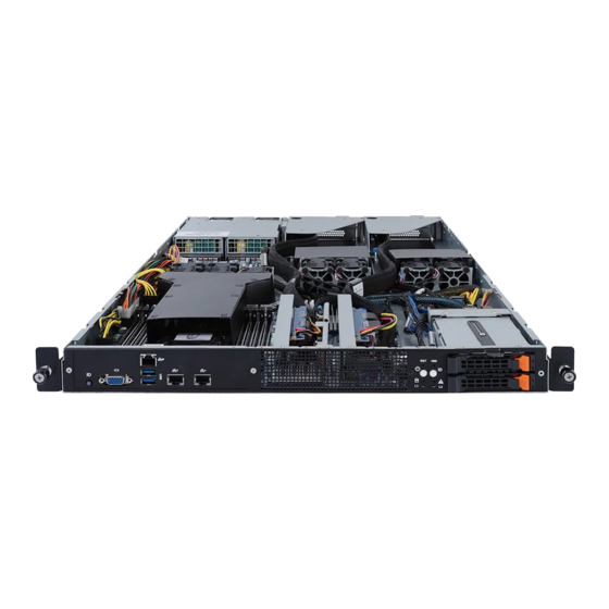
Chapter 2 System Appearance Front View 3 4 5 HDD0 HDD1 Description ID Button with LED VGA Port Server Management LAN Port USB 3.2 Port x 2 10G LAN Port x 2 Front Panel LEDs and Buttons • Please Go to Chapter 2-3 Front Panel LED and Buttons for detail description of function LEDs. -
Page 14: Front Panel Led And Buttons
Front Panel LED and Buttons Name Color Status Description Reset Button Press the button to reset the system. Press the button server generates a NMI to the processor NMI button if the multiple-bit ECC errors occur, which effectively halt the server. Green System is powered on Green... -
Page 15: System Lan Leds
System LAN LEDs Name Color Status Description Yellow 1Gbps data rate 1GbE Green 100 Mbps data rate Speed LED 10 Mbps data rate Link between system and 1GbE Green network or no access Link/ Blink Data transmission or receiving is occurring Activity No data transmission or receiving is occurring... -
Page 16: Power Supply Unit Led
Power Supply Unit LED PSU LED State Description No AC power to all power supplies 1Hz Green Blinking AC present / only standby on / Cold redundant mode 2Hz Green Blinking Power supply firmware updating mode AC cord unplugged or AC power lost; with a second power supply in parallel still with AC input power Amber Power supply critical event causing shut down:... -
Page 17: Hard Disk Drive Leds
Hard Disk Drive LEDs HDD Present RAID SKU Rebuilding LED1 Locate HDD Fault Access (No Access) Disk LED Green ON(*1) BLINK (*2) (LED on Back Panel) Amber No RAID configuration Green ON(*1) (via HBA) Removed HDD Slot (LED on Back Panel) Amber Green BLINK (*2) - Page 18 This page intentionally left blank System Appearance - 18 -...
-
Page 19: Chapter 3 System Hardware Installation
Chapter 3 System Hardware Installation Pre-installation Instructions Computer components and electronic circuit boards can be damaged electrostatic discharge. Working on computers that are still connected to a power supply can be extremely dangerous. Follow the simple guidelines below to avoid damage to your computer or injury to yourself. -
Page 20: Removing Chassis Cover
Removing Chassis Cover Before you remove or install the system cover • Make sure the system is not turned on or connected to AC power. Follow these instructions to remove the rear system cover: Loosen and remove the thumbscrew securing the top cover. Push down the indentation located at the side of the back chassis Slide the cover horizontally to the back and remove the cover in the direction of the arrow. -
Page 21: Removing And Installing The Fan Duct
Removing and Installing the Fan Duct Follow these instructions to remove/install the fan duct: Lift up to remove the two fan ducts To install the fan duct, align the fan duct with the guiding groove. Push down the fan duct into chassis until its firmly seats - 21 - System Hardware Installation... -
Page 22: Installing The Cpu And Heat Sink
Installing the CPU and Heat Sink Read the following guidelines before you begin to install the CPU: • Make sure that the motherboard supports the CPU. • Always turn off the computer and unplug the power cord from the power outlet before installing the CPU to prevent hardware damage. - Page 23 • When installing the heat sink over the CPU, use T30-Lobe driver to tighten the 4 captive nuts in sequential order (1g2g3g4). • The screw tightening torque: 8 ± 0.5kgf-cm (17.0± 1.0 lbf-in) - 23 - System Hardware Installation...
-
Page 24: Installing The Memory
Installing the Memory Read the following guidelines before you begin to install the memory: • Make sure that the motherboard supports the memory. It is recommended that memory of the same capacity, brand, speed, and chips be used. • Always turn off the computer and unplug the power cord from the power outlet before installing the memory to prevent hardware damage. -
Page 25: Installing A Memory
3-4-2 Installing a Memory Before installing a memory module, make sure to turn off the computer and unplug the power cord from the power outlet to prevent damage to the memory module. Be sure to install DDR4 DIMMs on this motherboard. NOTE! DIMM must be populated in order starting from A1/B1/C1/D1 socket. -
Page 26: Installing The Gpu Card
Installing the GPU Card Before you install the GPU card: Voltages can be present within the server whenever an AC power source is connected. This voltage is present even when the main power switch is in the off position. Ensure that the system is powered down and all power sources have been disconnected from the server prior to installing a GPU card. -
Page 27: Installing The Hard Disk Drive
Installing the Hard Disk Drive Read the following guidelines before you begin to install the Hard disk drive: • Take note of the drive tray orientation before sliding it out. • The tray will not fit back into the bay if inserted incorrectly. •... -
Page 28: Installing And Removing An M.2 Solid State Drive
Installing and Removing an M.2 Solid State Drive Follow these instructions to install an optional M.2 solid state drive (SSD): NOTE: To install/remove the M.2 heatsink use a No. 1 Phillips-head screwdriver with a screw torque of 1.5 ± 0.2 kgf*cm Place the solid state drive into the M.2 connector. -
Page 29: Replacing The Fan Assembly
Replacing the FAN Assembly • Voltages can be present within the server whenever an AC power source is connected. This voltage is present even when the main power switch is in the off position. Ensure that the system is powered-down and all power sources have been disconnected from the server prior to removing/installing a system fan. -
Page 30: Replacing The Power Supply
Replacing the Power Supply Follow these instructions to replace the power supply: Press the retaining clip on the left side of the power supply unit along the direction of the arrow. Pull the power supply handle at the same time and pull out the power supply unit. Insert the replacement power supply unit firmly into the chassis. -
Page 31: Cable Routing
3-10 Cable Routing Front Switch Cable/Front LED Cable On-Board SATA to HDD Back Plane Board Cable - 31 - System Hardware Installation... - Page 32 HDD Back Plane Board Signal Cable HDD Back Plane Board Power Cable System Hardware Installation - 32 -...
- Page 33 Motherboard Power Cable CPU Power Cable - 33 - System Hardware Installation...
- Page 34 12V Power Cable Fan Board Power Cable System Hardware Installation - 34 -...
- Page 35 GPU Card Power Cable GPU Card Signal Cable - 35 - System Hardware Installation...
- Page 36 NMVe to HDD Back Plane Board Cable System Hardware Installation - 36 -...
-
Page 37: Chapter 4 Motherboard Components
Chapter 4 Motherboard Components Motherboard Components 19 20 Item Description TPM Module Connector 2 x 4 Pin 12V Power Connector PMBus Connector 2 x 12 Pin System Power Connector 2 x 4 Pin 12V Power Connector SlimLine SAS 4i Connector (SL_SAS1/SATA III/NVMe Signal) SlimLine SAS 4i Connector (SL_SAS2/SATA III/NVMe Signal) System Fan Connector System Fan Connector... -
Page 38: Jumper Settings
Jumper Settings Default Clear CMOS CLR_CMOS Enable Motherboard Components - 38 -... -
Page 39: Chapter 5 Bios Setup
Chapter 5 BIOS Setup BIOS (Basic Input and Output System) records hardware parameters of the system in the EFI on the motherboard. Its major functions include conducting the Power-On Self-Test (POST) during system startup, saving system parameters, loading the operating system etc. The BIOS includes a BIOS Setup program that allows the user to modify basic system configuration settings or to activate certain system features. - Page 40 Main This setup page includes all the items of the standard compatible BIOS. Advanced This setup page includes all the items of AMI BIOS special enhanced features. (ex: Auto detect fan and temperature status, automatically configure hard disk parameters.) ...
-
Page 41: The Main Menu
The Main Menu Once you enter the BIOS Setup program, the Main Menu (as shown below) appears on the screen. Use arrow keys to move among the items and press <Enter> to accept or enter other sub-menu. Main Menu Help The on-screen description of a highlighted setup option is displayed on the bottom line of the Main Menu. - Page 42 Parameter Description BIOS Information Project Name Displays the project name information. Project Version Displays version number of the BIOS setup utility. Build Date and Time Displays the date and time when the BIOS setup utility was created. BMC Information (Note1) BMC Firmware Version (Note1) Displays BMC firmware version information.
- Page 43 Parameter Description Onboard LAN Information LAN1 MAC Address (Note) Displays LAN MAC address information. LAN2 MAC Address (Note) Displays LAN MAC address information. System Date Sets the date following the weekday-month-day-year format. System Time Sets the system time following the hour-minute-second format. (Note) The number of LAN ports listed will depend on the motherboard / system model.
-
Page 44: Advanced Menu
Advanced Menu The Advanced Menu displays submenu options for configuring the function of various hardware components. Select a submenu item, then press <Enter> to access the related submenu screen. BIOS Setup - 44 -... -
Page 45: Trusted Computing
5-2-1 Trusted Computing Parameter Description TPM20 Device Found Firmware Version Displays the firmware version information. Vendor Displays the vendor information. Enable/Disable BIOS support for security device. OS will not show security device. TCG EFI protocol and INT1A interface will not be Security Device Support available. - Page 46 Parameter Description Schedule an operation for the security device. NOTE: Your computer will reboot during restart in order to change Pending operation the state of a security device. Options available: None, TPM Clear. Default setting is None. Enable/Disable platform hierarchy. Platform Hierarchy Options available: Enabled, Disabled.
-
Page 47: Ast2500 Super Io Configuration
5-2-2 AST2500 Super IO Configuration Description Parameter AST2500 Super IO Configuration Super IO Chip Displays the super IO chip information Serial Port 1 Press [Enter] for configuration of advanced items. Configuration - 39 - BIOS Setup... - Page 48 5-2-2-1 Serial Port 1 Configuration Description Parameter Serial Port 1 Configuration Enable/Disable the Serial Port (COM). When set to Enabled allows you to configure the Serial port 1 settings. When set to Disabled, displays no Serial Port (Note1) configuration for the serial port. Options available: Enabled, Disabled.
-
Page 49: S5 Rtc Wake Settings
5-2-3 S5 RTC Wake Settings Parameter Description Enable/Disable system wake on alarm event. Options available: Disabled, Fixed Time, Dynamic Time. When Fixed Time is Wake System from S5 selected, system will wake on the hr::min::sec specified. Default setting is Disabled. - 39 - BIOS Setup... -
Page 50: Serial Port Console Redirection
5-2-4 Serial Port Console Redirection Parameter Description Select whether to enable console redirection for specified device. Console COM1/Serial Over LAN redirection enables the users to manage the system from a remote Console Redirection location. (Note)) Options available: Enabled, Disabled. Default setting is Disabled. Press [Enter] to configure advanced items. - Page 51 Parameter Description Parity Š – A parity bit can be sent with the data bits to detect some transmission errors. – Even: parity bit is 0 if the num of 1's in the data bits is even. – Odd: parity bit is 0 if num of 1's in the data bits is odd. –...
- Page 52 Parameter Description Legacy Console Redirection Press [Enter] to configure advanced items. Redirection COM Port Š – Selects a COM port for Legacy serial redirection. – Options available: COM1/SOL, COM2. Default setting is COM1/ SOL. Resolution Š – Selects the number of rows and columns used in Console Legacy Console Redirection Redirection for legacy OS support.
- Page 53 Parameter Description Flow Control EMS Š – Flow control can prevent data loss from buffer overflow. When sending data, if the receiving buffers are full, a 'stop' signal can Serial Port for Out-of-Band be sent to stop the data flow. Once the buffers are empty, a 'start' EMS Console Redirection signal can be sent to re-start the flow.
-
Page 54: Cpu Configuration
5-2-5 CPU Configuration Description Parameter Displays the module version information. Module Version Displays the AGESA version information. AGESA Version Enable/Disable the CPU Virtualization. SVM Mode Options available: Enabled, Disabled. Default setting is Disabled. Enable/Disable SVM lock. SVM Lock Options available: Enabled, Disabled. Default setting is Disabled. Enable/Disable SMM lock. -
Page 55: Ami Graphic Output Protocol Policy
5-2-6 AMI Graphic Output Protocol Policy Description Parameter ASPEED Graphics PCI Adapter ASPEED Graphics Driver Selects Monitor Output by Graphic Output Protocol. Output Select - 39 - BIOS Setup... -
Page 56: Pci Subsystem Settings
5-2-7 PCI Subsystem Settings Description Parameter Displays the PCI Bus Driver version information. PCI Bus Driver Version Enable/Disable SATA Hot Plug. SATA Hot Plug Options available: Enabled, Disabled. Default setting is Disabled. Enable/Disable NVMe RAID mode. NVMe RAID mode Options available: Enabled, Disabled. Default setting is Disabled. Change the SL_SAS function. - Page 57 Description Parameter PCI Devices Common Settings Enable/Disable memory mapped I/O to 4GB or greater address space (Above 4G Decoding). Above 4G Decoding Options available: Enabled, Disabled. Default setting is Enabled. If the system has SR-IOV capable PCIe devices, this item Enable/Disable Single Root IO Virtualization Support.
-
Page 58: Usb Configuration
5-2-8 USB Configuration Parameter Description USB Configuration USB Module Version Displays the USB module version information. USB Controllers Displays the supported USB controllers. USB Devices: Displays the USB devices connected to the system. Enable/Disable the Legacy USB support function. AUTO option disables legacy support if no USB devices are connected. - Page 59 Parameter Description Enables the I/O port 60h/64h emulation support. This should be enabled for the complete USB Keyboard Legacy support for non- Port 60/64 Emulation USB aware OS. Options available: Enabled, Disabled. Default setting is Enabled. USB hardware delays and time-outs Selects the time-out value for USB Control/Bulk/Interrupt transfers.
-
Page 60: Nvme Configuration
5-2-9 NVMe Configuration Parameter Description NVMe Configuration Displays the NVMe devices connected to the system. BIOS Setup - 60 -... -
Page 61: Sata Configuration
5-2-10 SATA Configuration Parameter Description Displays the installed HDD devices information. System will automatically SATA Configuration detect HDD type. - 39 - BIOS Setup... -
Page 62: Network Stack Configuration
5-2-11 Network Stack Configuration Parameter Description Enable/Disable the UEFI network stack. Network Stack Options available: Enabled, Disabled. Default setting is Enabled. Enable/Disable the Ipv4 PXE feature. Ipv4 PXE Support (Note) Options available: Enabled, Disabled. Default setting is Enabled. Enable/Disable the Ipv4 HTTP feature. Ipv4 HTTP Support (Note) Options available: Enabled, Disabled. -
Page 63: Amd Mem Configuration Status
5-2-12 AMD Mem Configuration Status Description Parameter Press [Enter] to view the memory configuration status related to CPU 0. CPU0 - 39 - BIOS Setup... -
Page 64: Amd Cbs
5-2-13 AMD CBS Parameter Description AMD CBS CPU Common Options Press [Enter] for configuration of advanced items. DF Common Options Press [Enter] for configuration of advanced items. UMC Common Options Press [Enter] for configuration of advanced items. NBIO Common Options Press [Enter] for configuration of advanced items. - Page 65 5-2-13-1 CPU Common Options Parameter Description CPU Common Options Press [Enter] for configuration of advanced items. Custom Core Pstates Š Performance – Allows you to accept or decline enabling Custom Core Pstates. When accepted, you can disable or customize core pstates. Press [Enter] for configuration of advanced items.
- Page 66 Parameter Description From a workaround for GCC/C000005 issue for XV Core on CZ A0, setting MSRC001_1029 Decode Configuration (DE_CFG) bit 14 RedirectForReturnDis [DecfgNoRdrctForReturns] to 1. Options available: Auto , 1, 0. Default setting is Auto. Enable/Disable PFEH, cloak individual banks, and mask deferred error Platform First Error Handling interrupts from each bank.
- Page 67 5-2-13-2 DF Common Options Parameter Description DF Common Options Press [Enter] for configuration of advanced items. DRAM scrub time Š – Provide a value that is the number of hours to scrub memory. – Options available: Auto, Disabled, 1 hour, 4 hours, 8 hours, 16 hours, 24 hours, 48 hours.
- Page 68 Parameter Description Memory interleaving size Š – Controls the memory interleaving size. This determines the starting address of the interleave (bit 8, 9, 10 or 11). – Options available: Auto, 256Bytes, 512Bytes, 1KB, 2KB. Default setting is Auto. 1TB remap Š...
- Page 69 Parameter Description xGMI TXEQ Mode Š Link – Configures xGMI TXEQ/RX vetting Mode. (continued) – Options available: Auto, TXEQ_Disabled, TXEQ_Lane, TXEQ_Link, TXEQ_RX_Vet. Default setting is Auto. Disable DF to external Enable/Disable SyncFlood to UMC & downstream slaves. downstream IP Options available: Auto, Sync flood disabled, Sync flood enabled. SyncFloodPropagation Default setting is Auto.
- Page 70 5-2-13-3 UMC Common Options Parameter Description UMC Common Options DDR4 Common Options Press [Enter] for configuration of advanced items. DRAM Memory Mapping Press [Enter] for configuration of advanced items. NVDIMM Press [Enter] for configuration of advanced items. Memory MBIST Press [Enter] for configuration of advanced items. BIOS Setup - 70 -...
- Page 71 5-2-13-3-1 DDR4 Common Options Parameter Description DDR4 Common Options Press [Enter] to enable / disable restrictions for DDR4 frequency and voltage programming. Memory speeds will be capped at AMD guidelines. Decline Š DRAM Timing Configuration Accept Š – Overclock: Enable/Disable Memory Overclock Settings. –...
- Page 72 Parameter Description CAD Bus Drive Strength User Controls Š CAD Bus Configuration – Drive Strength on CAD bus signals to Auto or Manual. (continued) – Options available: Auto, Manual. Default setting is Auto. Press [Enter] for configuration of advanced items. Data Bus Configuration User Controls Š...
- Page 73 Parameter Description – DRAM ECC Enable » Enable/Disable DRAM ECC. When set to Auto, it will set ECC to enable. » Options available: Auto, Enabled, Disabled. Default setting is Common RAS Auto. (continued) – DRAM UECC Retry » Enable/Disable DRAM UECC Retry. »...
- Page 74 5-2-13-3-2 DRAM Memory Mapping Parameter Description DRAM Memory Mapping Interleave memory blocks across the DRAM chip selects for node 0. Chipselect Interleaving Options available: Auto, Disabled. Default setting is Auto. Configures the BankGroupSwap. BankGroupSwap (BGS) is a new memory mapping option in AGESA that alters how applications get assigned to BankGroupSwap physical locations within the memory modules.
- Page 75 5-2-13-3-3 NVDIMM Parameter Description NVDIMM Displays the information of the devices/controllers if installed Disable NVDIMM-N Enable/Disable NVDIMM-N feature for memory margin tool. Feature Options available: No, Yes. Default setting is NO. - 39 - BIOS Setup...
- Page 76 5-2-13-3-4 Memory MBIST Parameter Description Memory MBIST Enable/Disable the Memory MBIST function. MBIST Enable Options available: Enabled, Disabled. Default setting is Disabled. Selects MBIST Test Mode. Interface Mode: Tests Single and Multiple CS transactions and Basic Connectivity. MBIST Test Mode (Note) Data Eye Mode: Measures Voltage vs.
- Page 77 Parameter Description Aggressor Channel Š – This item helps read the aggressors channels. – Options available: Disabled, 1 Aggressor Channel, 3 Aggressor Channels, 7 Aggressor Channels. Default setting is 1 Aggressor Channel. Aggressor Static Lane Control Š – Enable/Disable the Aggressor Static Lane Control function. –...
- Page 78 5-2-13-4 NBIO Common Options Parameter Description NBIO Common Options Enable/Disable the IOMMU function. IOMMU Options available: Auto, Enabled, Disabled. Default setting is Auto. Press [Enter] to configure advanced items. Declined Š Accepted Š – Precision Boost Overdrive » Options available: Auto, Enable, Disable, Manual. Default setting is Auto.
- Page 79 Parameter Description VDDG Voltage Control Š – Options available: Auto, Manual. Default setting is Auto. SoC/Uncore OC Mode Š – Forces CPU SoC/Uncore components (e.g. Infinity Fabric, memory, and integrated graphics) to run at their maximum specified frequency XFR Enhancement at all times.
- Page 80 CPPC Preferred Cores Š – Options available: Auto, Enabled, Disabled. Default setting is Auto. SMU Common Options NBIO LCLK DPM Š (continued) – This setting controls how the NBIO Power Management is controlled. – Options available: Auto, Manual. Default setting is Auto. Enable/Disable Advanced Error Reporting Capability.
- Page 81 5-2-13-5 FCH Common Options Parameter Description FCH Common Options Press [Enter] for configuration of advanced items. SATA Enable Š – Enable/Disable OnChip SATA controller. – Options available: Auto, Enabled, Disabled. Default setting is Auto. SATA RAS Support Š – Enable/Disable SATA RAS Support. –...
- Page 82 5-2-13-6 SOC Miscellaneous Control Parameter Description SOC Miscellaneous Control Enable/Disable the ConsoleOut function for ABL. ABL Console Out Control Options available: Auto, Enabled, Disabled. Default setting is Auto. ABL Basic Console Out Enable/Disable the Basic ConsoleOut function for ABL. Options available: Auto, Enabled, Disabled. Default setting is Auto. Control (Note) To Control the total number of PMU debug messages.
- Page 83 5-2-13-7 X570/590 Chipset Common Options Parameter Description X570/590 Chipset Common Options Press [Enter] for configuration of advanced items. X570/590 Chipset SATA0/1 Enable Š – Enable/Disable Bixby SATA controller. – Options available: Auto, Enabled, Disabled. Default setting is Auto. X570/590 Chipset SATA X570/590 Chipset SATA Disabled AHCI Prefetch Function Š...
-
Page 84: Iscsi Configuration
5-2-14 iSCSI Configuration Parameter Description Press [Enter] and name iSCSI Initiator. Only IQN format is accepted. iSCSI Initiator Name Range: from 4 to 223 Add an Attempt Press [Enter] to configure advanced items. Delete Attempts Press [Enter] to configure advanced items. Change Attempt Order Press [Enter] to configure advanced items. -
Page 85: Intel X550 10Gbase-T Network Connection
5-2-15 Intel X550 10GBASE-T Network Connection Parameter Description Press [Enter] to view firmware image information. Firmware Image Properties Link Speed Š – Allows for automatic link speed adjustment. – Options available: Auto Negotiated, 10 Mbps Half, 10 Mbps Full, 100 Mbps Half, 100 Mbps Full. Default setting is Auto Negotiated. Wake On LAN Š... - Page 86 Parameter Description Specifies the link status of the port. Link Status Displays the MAC address of the Ethernet controller. MAC Address Displays the virtual MAC address of the Ethernet controller. Virtual MAC Address BIOS Setup - 86 -...
-
Page 87: Vlan Configuration
5-2-16 VLAN Configuration - 39 - BIOS Setup... - Page 88 Parameter Description Press [Enter] to configure advanced items. Create new VLAN Š VLAN ID Š – Sets VLAN ID for a new VLAN or an existing VLAN. – Press the <+> / <-> keys to increase or decrease the desired values. –...
-
Page 89: Mac Ipv4 Network Configuration
5-2-17 MAC IPv4 Network Configuration Parameter Description Indicates whether network address is configured successfully or not. Configured Options available: Enabled, Disabled. Default setting is Disabled. Options available: Enabled, Disabled. Default setting is Enabled. Enable DHCP (Note) Local IP Address Press [Enter] to configure local IP address. (Note) Press [Enter] to configure local NetMask. -
Page 90: Mac Ipv6 Network Configuration
5-2-18 MAC IPv6 Network Configuration BIOS Setup - 90 -... - Page 91 Parameter Description Press [Enter] to configure advanced items. Displays the MAC Address information. Š Interface ID Š – The 64 bit alternative interface ID for the device. The string is colon separated. e.g. ff:dd:88:66:cc:1:2:3. DAD Transmit Count Š – The number of consecutive Neighbor solicitation messages sent Enter Configuration Menu while performing Duplicate Address Detection on a tentative address.
-
Page 92: Chipset Setup Menu
Chipset Setup Menu Chipset Setup menu displays submenu options for configuring the function of the South Bridge and North Bridge. Select a submenu item, then press <Enter> to access the related submenu screen. Parameter Description South Bridge Press [Enter] for configuration of advanced items. North Bridge Press [Enter] for configuration of advanced items. -
Page 93: South Bridge
5-3-1 South Bridge Parameter Description Press [Enter] for configuration of advanced items. DIE0/1 XHCI Port Š SB USB Configuration – Enable/Disable XHCI Port. – Options available: Enabled, Disabled. Default setting is Enabled. - 39 - BIOS Setup... -
Page 94: North Bridge
5-3-2 North Bridge Parameter Description North Bridge Configuration Selects Above 4GB MMIO Limit to 38~43 bits limit. This option works only when "Above 4G decoding" is enabled. Above 4GB MMIO Limit Options available: 40bit (1TB), 41bit (2TB), 42bit (4TB), 43bit (8TB). Default setting is 40bit (1TB). -
Page 95: Server Management Menu
Server Management Menu Parameter Description Enable/Disable FRB-2 timer (POST timer). FRB-2 Timer Options available: Enabled, Disabled. Default setting is Enabled. Configures the FRB2 Timer timeout. FRB-2 Timer (Note1) Options available: 3 minutes, 4 minutes, 5 minutes, 6 minutes. Default setting is 6 timeout minutes. - Page 96 Parameter Description View FRU Press [Enter] to view the FRU information. Information BMC VLAN Press [Enter] to configure advanced items. Configuration BMC network Press [Enter] to configure advanced items. configuration IPv6 BMC Network Press [Enter] to configure advanced items. Configuration BIOS Setup - 96 -...
-
Page 97: System Event Log
5-4-1 System Event Log Parameter Description Enabling / Disabling Options Change this item to enable or disable all features of System Event SEL Components Logging during boot. Options available: Enabled, Disabled. Default setting is Enabled. Erasing Settings Choose options for erasing SEL. Erase SEL Options available: No/Yes, On next reset/Yes, On every reset. -
Page 98: View Fru Information
5-4-2 View FRU Information The FRU page is a simple display page for basic system ID information, as well as System product information. Items on this window are non-configurable. (Note) The model name will vary depends on the product you purchased BIOS Setup - 98 -... -
Page 99: Bmc Vlan Configuration
5-4-3 BMC VLAN Configuration Parameter Description BMC VLAN Configuration Sets VLAN ID for a new VLAN or an existing VLAN. BMC VLAN ID Press the <+> / <-> keys to increase or decrease the desired values. The valid range is from 0 to 4094. Sets 802.1Q Priority for a new VLAN or an existing VLAN. -
Page 100: Bmc Network Configuration
5-4-4 BMC Network Configuration Parameter Description BMC network configuration Lan Channel 1 Selects to configure LAN channel parameters statically or dynamically (DHCP). Do nothing option will not modify any BMC network parameters Configuration Address source during BIOS phase. Options available: Unspecified, Static, DynamicBmcDhcp. Default setting is DynamicBmcDhcp. -
Page 101: Ipv6 Bmc Network Configuration
5-4-5 IPv6 BMC Network Configuration Parameter Description IPv6 BMC network configuration IPv6 BMC Lan Channel 1 Enable/Disable IPv6 BMC LAN channel function. When this item is disabled, the system will not modify any BMC network during BIOS IPv6 BMC Lan Option phase. -
Page 102: Security Menu
Security Menu The Security menu allows you to safeguard and protect the system from unauthorized use by setting up access passwords. There are two types of passwords that you can set: • Administrator Password Entering this password will allow the user to access and change all settings in the Setup Utility. •... -
Page 103: Secure Boot
5-5-1 Secure Boot The Secure Boot submenu is applicable when your device is installed the Windows 8 (or above) operating ® system. Parameter Description System Mode Displays if the system is in User mode or Setup mode. Enable/ Disable the Secure Boot function. Secure Boot Options available: Enabled, Disabled. - Page 104 Parameter Description Press [Enter] to configure advanced items. Please note that this item is configurable when Secure Boot Mode is set to Custom. Factory Key Provision Š – Allows to provision factory default Secure Boot keys when system is in Setup Mode.
-
Page 105: Boot Menu
Boot Menu The Boot menu allows you to set the drive priority during system boot-up. BIOS setup will display an error message if the legacy drive(s) specified is not bootable. Parameter Description Boot Configuration Number of seconds to wait for setup activation key. 65535 (0xFFFF) Setup Prompt Timeout means indefinite waiting. - Page 106 Parameter Description FIXED BOOT ORDER Priorities Press [Enter] to configure the boot priority. By default, the server searches for boot devices in the following sequence: Hard drive. Boot Option #1 / #2 / #3 / #4 / #5 CD-COM/DVD drive. USB device.
-
Page 107: Save & Exit Menu
Save & Exit Menu The Save & Exit menu displays the various options to quit from the BIOS setup. Highlight any of the exit options then press <Enter>. Parameter Description Save Options Saves changes made and closes the BIOS setup. Save Changes and Exit Options available: Yes, No. -
Page 108: Bios Post Beep Code (Ami Standard)
BIOS POST Beep code (AMI standard) 5-8-1 PEI Beep Codes # of Beeps Description Memory not Installed. Memory was installed twice (InstallPeiMemory routine in PEI Core called twice) Recovery started DXEIPL was not found DXE Core Firmware Volume was not found Recovery failed S3 Resume failed Reset PPI is not available...