
Related Manuals for Gigabyte G292-Z20


Summary of Contents for Gigabyte G292-Z20
- Page 1 G292-Z20 G292-Z22 HPC Server - 2U UP 8 x Gen4 GPU Server ( Microchip solution) HPC Server - 2U UP 8 x Gen3 GPU Server User Manual Rev. 1.0...
- Page 2 GIGABYTE's prior written permission. Documentation Classifications In order to assist in the use of this product, GIGABYTE provides the following types of documentation: User Manual: detailed information & steps about the installation, configuration and use of this product (e.g.
- Page 3 Conventions The following conventions are used in this user's guide: NOTE! Gives bits and pieces of additional information related to the current topic. CAUTION! Gives precautionary measures to avoid possible hardware or software problems. WARNING! Alerts you to any damage that might result from doing or not doing specific actions.
- Page 4 Server Warnings and Cautions Before installing a server, be sure that you understand the following warnings and cautions. WARNING! To reduce the risk of electric shock or damage to the equipment: • Do not disable the power cord grounding plug. The grounding plug is an important safety feature.
- Page 5 Electrostatic Discharge (ESD) CAUTION! ESD CAN DAMAGE DRIVES, BOARDS, AND OTHER PARTS. WE RECOMMEND THAT YOU PERFORM ALL PROCEDURES AT AN ESD WORKSTATION. IF ONE IS NOT AVAILABLE, PROVIDE SOME ESD PROTECTION BY WEARING AN ANTI-STATIC WRIST STRAP AT- TACHED TO CHASSIS GROUND -- ANY UNPAINTED METAL SURFACE -- ON YOUR SERVER WHEN HANDLING PARTS.
- Page 6 CAUTION! Risk of explosion if battery is replaced incorrectly or with an incorrect type. Replace the battery only with the same or equivalent type recommended by the manufacturer. Dispose of used bat- teries according to the manufacturer’s instructions.
-
Page 7: Table Of Contents
Table of Contents Chapter 1 Hardware Installation ................... 11 Installation Precautions .................. 11 Product Specifications ..................12 System Block Diagram ................... 16 1-3-1 G292-Z20 .......................16 1-3-2 G292-Z22 .......................16 Chapter 2 System Appearance ..................17 Front View ...................... 17 Rear View ....................... 18 Front Panel Buttons and LEDs ............... - Page 8 5-2-1 Trusted Computing ....................63 5-2-2 PSP Firmware Versions ..................64 5-2-3 Legacy Video Select ....................65 5-2-4 AST2500 Super IO Configuration ................66 5-2-5 S5 RTC Wake Settings ...................69 5-2-6 Serial Port Console Redirection ................70 5-2-7 CPU Configuration ....................74 5-2-8 PCI Subsystem Settings ..................75 5-2-9 USB Configuration ....................77 5-2-10 Network Stack Configuration ..................79...
- Page 9 5-8-1 UEFI NETWORK Drive BBS Priorities ..............145 ..............146 5-8-2 UEFI Application Boot Priorities Save & Exit Menu ..................147 5-10 BIOS POST Beep code (AMI standard) ............148 5-10-1 PEI Beep Codes ....................148 5-10-2 DXE Beep Codes ....................148 - 9 -...
- Page 10 - 10 -...
-
Page 11: Chapter 1 Hardware Installation
Chapter 1 Hardware Installation Installation Precautions The motherboard/system contain numerous delicate electronic circuits and components which can become damaged as a result of electrostatic discharge (ESD). Prior to installation, carefully read the service guide and follow these procedures: • Prior to installation, do not remove or break motherboard S/N (Serial Number) sticker or warranty sticker provided by your dealer. -
Page 12: Product Specifications
Product Specifications NOTE: We reserve the right to make any changes to the product specifications and product-related informa- tion without prior notice. AMD EPYC™ 7003 processors with AMD 3D V-Cache™ Technology Š AMD EPYC™ 7003 series processor family Š Single processor, 7nm technology Š... - Page 13 - Maximum limitation of GPU card: 285mm (L) x 111.5mm (W) x 39.5mm (H) - System is validated for population with a uniform GPU model - Support is not provided for mixed GPU populations - For the latest GPU cards QVL, please contact your GIGABYTE representative - 13 - Hardware Installation...
- Page 14 - Maximum limitation of GPU card: 285mm (L) x 111.5mm (W) x 39.5mm (H) - System is validated for population with a uniform GPU model - Support is not provided for mixed GPU populations - For the latest GPU cards QVL, please contact your GIGABYTE representative Internal I/O 1 x TPM header Š...
- Page 15 +12.12V/ 178.1A +12Vsb/ 3.5A NOTE: The system power supply requires C19 type power cord. System Aspeed® AST2500 management controller Š Management GIGABYTE Management Console (AMI MegaRAC SP-X) web interface Š Dashboard Š JAVA Based Serial Over LAN Š HTML5 KVM Š...
-
Page 16: System Block Diagram
System Block Diagram 1-3-1 G292-Z20 Riser Card 8-bay 2.5” SATA with 2-bay 2.5” Gen3 U.2 PCIe switch Microsemi PCIe4.0 x16 Riser Card 8-Channel DDR4, 8 x DIMMs PCIe switch Speed up to 3200 MHz Microsemi PCIe4.0 x16 Riser Card PCIe switch Microsemi PCIe4.0 x16... -
Page 17: Chapter 2 System Appearance
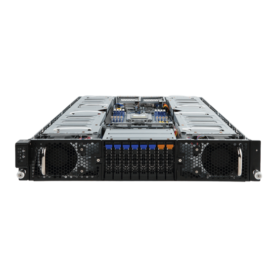
Chapter 2 System Appearance Front View Description Front Panel LED and Buttons GPU Fan (GPU78_FAN) GPU Fan (GPU56_FAN) NOTE! The Orange Latch Supports NVMe • Go to the section for detail description of function 2-3 Front Panel Buttons and LEDs LEDs. -
Page 18: Rear View
Rear View 6 7 8 PSU1 PSU2 Description System Fan (GPU12E_FAN) VGA Port PCIe Card Slot Power Button with LED ID Button Reset Button System Status LED PCIe Card Slot LAN Port #1/#2 Active/Link LED USB 3.0 Port x 2 System Fan (GPU56E_FAN) 10G LAN Port x 2 NMI Button... -
Page 19: Front Panel Buttons And Leds
Front Panel Buttons and LEDs No. Name Color Status Description Indicates a link between the system and the network or Green LAN1/2 no access. 1/2. Active/ Green Blink Indicates data trasmission or receiving is occuring. Link LED Indicates no data transmission or receiving is occuring. Indicates locating the HDD. -
Page 20: Rear System Lan Leds
Rear System LAN LEDs 3 4 3 4 Name Color Status Description Yellow 1 Gbps data rate 1GbE Speed Green 100 Mbps data rate 10 Mbps data rate Link between system and network or no access Green 1GbE Link / Blink Data transmission or reception is occurring. -
Page 21: Power Supply Unit (Psu) Led
Power Supply Unit (PSU) LED PSU LED Color Status Description No AC power to all power supplies Blinking Green AC present / Only +12VSB on (PS off) or PSU in Smart Standby Mode 0.5Hz Blinking Green Power supply firmware update AC cord unplugged / AC power lost but a second power supply in parallel still having AC input power Amber... -
Page 22: Hard Disk Drive Leds
Hard Disk Drive LEDs LED#1 LED#2 (Reserved) HDD Present RAID SKU Rebuilding LED1 Locate HDD Fault Access (No Access) Disk LED Green ON(*1) BLINK (*2) (LED on Back Panel) Amber No RAID configuration Green ON(*1) (via HBA) Removed HDD Slot (LED on Back Panel) Amber Green... -
Page 23: Chapter 3 System Hardware Installation
Chapter 3 System Hardware Installation Pre-installation Instructions Computer components and electronic circuit boards can be damaged electrostatic discharge. Working on computers that are still connected to a power supply can be extremely dangerous. Follow the simple guidelines below to avoid damage to your computer or injury to yourself. •... -
Page 24: Removing Chassis Cover
Removing Chassis Cover Before you remove or install the system cover • Make sure the system is not turned on or connected to AC power. Follow these instructions to remove the system cover: Remove the eight screws securing the cover. Slide the cover towards the rear and remove the cover in the direction of the arrow. -
Page 25: Removing And Installing The Fan Duct
Removing and Installing the Fan Duct Follow these instructions to remove/install the fan duct: Lift up to remove the fan duct To install the fan duct, align the tabs at the front of the fan duct with the slots in the system fan compartment as shown in the image below, and then push down the fan duct into chassis until its firmly seats - 25 -... -
Page 26: Installing The Cpu And Heat Sink
Installing the CPU and Heat Sink Read the following guidelines before you begin to install the heat Sink: Always turn off the computer and unplug the power cord from the power outlet before installing the heat sink to prevent hardware damage. Unplug all cables from the power outlets. - Page 27 - 27 - System Hardware Installation...
- Page 28 Follow these instructions to install the CPU: Align and install the processor on the carrier, making sure to line up the triangle markers on the corner of the CPU to the triangle mark on the corner of the CPU carrier. Slide the carrier assembly into the channels of the carrier bracket Close the carrier bracket so that it firmly latches on to the CPU socket.
- Page 29 • When installing the heat sink over the CPU, use T30-Lobe driver to tighten the 4 captive nuts in sequential order (1g2g3g4). • The screw tightening torque: 8 ± 0.5kgf-cm (17.0± 1.0 lbf-in) - 29 - System Hardware Installation...
-
Page 30: Installing The Memory
Installing the Memory Read the following guidelines before you begin to install the memory: • Make sure that the motherboard supports the memory. It is recommended that memory of the same capacity, brand, speed, and chips be used. • Always turn off the computer and unplug the power cord from the power outlet before installing the memory to prevent hardware damage. -
Page 31: Installing A Memory
3-4-2 Installing a Memory Before installing a memory module, make sure to turn off the computer and unplug the power cord from the power outlet to prevent damage to the memory module. Be sure to install DDR4 DIMMs on this motherboard. Follow these instructions to install the Memory: Insert the DIMM memory module vertically into the DIMM slot, and push it down. -
Page 32: Memory Population Table
3-4-4 Memory Population Table • When only one DIMM is used, it must be populated in memory slot DIMM1. EPYC Memory Speed based on DIMM Population (One DIMM per Channel) DIMM Population DIMM Max EPYC 7003 Type DDR Frequency (MHz) DIMM 0 1R (1 Rank) 3200... -
Page 33: Installing The Gpu Card
Installing the GPU Card • Voltages can be present within the server whenever an AC power source is connected. This voltage is present even when the main power switch is in the off position. Ensure that the system is powered-down and all power sources have been disconnected from the server prior to installing a PCI card. - Page 34 (For GPU7/GPU8) (For GPU1/GPU2) Top: GPU1 (PCIE_1_PCIE_1) Bo om: GPU2 (PCIE_1_PCIE_2) REAR REAR FRONT FRONT Top: GPU7 (PCIE_4_PCIE_1) Bo om: : GPU8 (PCIE_4_PCIE_2) System Hardware Installation - 34 -...
- Page 35 - 35 - System Hardware Installation...
- Page 36 For GPU3/GPU4/GPU5/GPU6 Follow these instructions to install the GPU card: [For GPU5/GPU6] Loosen and remove the two screws securing the PCI cage at the top of the system. [For GPU2/GPU3] Loosen and remove the single screw at the top of the system and the two screws at the rear of the system securing the PCI cage.
- Page 37 (For GPU3/GPU4) - 37 - System Hardware Installation...
-
Page 38: Installing A Pci Express Card
Installing a PCI Express Card • Voltages can be present within the server whenever an AC power source is connected. This voltage is present even when the main power switch is in the off position. Ensure that the system is powered-down and all power sources have been disconnected from the server prior to installing a PCI card. - Page 39 Follow these instructions to install a PCI Express x16 card on left side of the system: Loosen the thumbnail screw securing the PCI Express card bracket on the left side of the system. Remove the PCIe card bracket from the system. Install the PCIe card into the bracket.
- Page 40 IMPORTANT If you are installing an add-on card and want to support NVMe hard drives, the OCP switch located near the proprietary PCIe x8 mezzanine connector at the rear of the system (#37 in the 4-1 Motherboard Components section) must be set to off (labeled 1), as seen in the image below. Once the OCP switch is set to off, the proprietary PCIe x8 mezzanine connector's functionality will be disabled, and the Slimline 4i connectors for NVMe storage (#15 &...
-
Page 41: Installing The Hard Disk Drive
Slide the hard drive tray into the bay until it locks in place. CAUTION! We strongly recommend using enterprise level hard disk drives in the Gigabyte server system. For more information of recommended HDDs, please visit the Gigabyte website: https://www.gigabyte.com and search for the specific product QVL from Support & Downloads. -
Page 42: Replacing The Fan Assembly
Replacing the FAN Assembly CAUTION! Before you remove or install the system fans follow these steps: • Make sure the system is not turned on or connected to the AC power.. • Disconnect all necessary cable connections. Failure to observe these warnings could result in personal injury or damage to the equipment. - Page 43 Airflow direction Airflow direction [For SYS_FAN1/SYS_FAN2] Disconnect the fan cable and then lift up the fan assembly from the chassis. Reverse the previous steps to install the replacement fan assembly. - 43 - System Hardware Installation...
- Page 44 Airflow direction [For GPU12E_FAN/GPU56E_FAN] Disconnect the fan cable and then loosen and remove the screws securing the fan cage. Remove the fan cage from the system Reverse the previous steps to install the replacement fan assembly. System Hardware Installation - 44 -...
- Page 45 Airflow direction CAUTION! • To avoid fan cable damage, please make sure the fan cables are firmly seated in the cable routing hooks. - 45 - System Hardware Installation...
-
Page 46: Replacing The Power Supply
Replacing the Power Supply CAUTION! • In order to reduce the risk of injury from electric shock, disconnect AC power from the power supply before removing it from the system. Follow these instructions to replace the power supply: Pull up the power supply handle and press the retaining clip on the right side of the power supply along the direction of the arrow. -
Page 47: Cable Routing
3-10 Cable Routing System Main Power MB/Top Tray Connector System Fan Power - 47 - System Hardware Installation... - Page 48 CPU Power MB/Top Tray Connector 1 x 3 Power System Hardware Installation - 48 -...
- Page 49 HDD Backplane Board Signal HDD Backplane Board Signal - 49 - System Hardware Installation...
- Page 50 Power Distribution Board to HDD Backplane Board Power SlimLine SAS #1 MB/Top Tray Connector System Hardware Installation - 50 -...
- Page 51 SlimLine SAS #2 MB/Top Tray Connector Front Panel IO - 51 - System Hardware Installation...
- Page 52 System Hardware Installation - 52 -...
-
Page 53: Chapter 4 Motherboard Components
Chapter 4 Motherboard Components Motherboard Components DIMM_P0_H0 DIMM_P0_G0 DIMM_P0_F0 DIMM_P0_E0 CPU0 DIMM_P0_A0 DIMM_P0_B0 DIMM_P0_C0 DIMM_P0_D0 15 16 17 18 19 20 21 Item Description Rear VGA Port Serial Port Connector 12V Standby Power Connector (for system power) 10/100/1000 Server Management LAN Port IPMB Connector Power Button with LED ID Button with LED... - Page 54 PCIe x16 slot #3 PCIe x16 slot #1 2 x 9 Pin System Power Connector (system main power) Case Open Intrusion Header Proprietary PCIe x16 slot TPM connector Proprietary PCIe x8 slot x 2 (Mezzanine Slots For NCSI Switch Function) Motherboard Components - 54 -...
-
Page 55: Jumper Setting
Jumper Setting Core Chipset BMC Default Enable NCSI Switch BIOS PMBUS Address Recovery Select BIOS_RCVR PSMB_SEL1 1 2 3 1 2 3 Mezzanine Slot Onboard LAN Default Enable Default Enable Enable Default Password Power On Clear CMOS Clear Select CLR_CMOS1 BIOS_PWD S3_MASK 1 2 3... - Page 56 This page intentionally left blank Motherboard Components - 56 -...
-
Page 57: Chapter 5 Bios Setup
Chapter 5 BIOS Setup BIOS (Basic Input and Output System) records hardware parameters of the system in the EFI on the motherboard. Its major functions include conducting the Power-On Self-Test (POST) during system startup, saving system parameters, loading the operating system etc. The BIOS includes a BIOS Setup program that allows the user to modify basic system configuration settings or to activate certain system features. - Page 58 Main This setup page includes all the items of the standard compatible BIOS. Advanced This setup page includes all the items of AMI BIOS special enhanced features. (ex: Auto detect fan and temperature status, automatically configure hard disk parameters.) ...
-
Page 59: The Main Menu
The Main Menu Once you enter the BIOS Setup program, the Main Menu (as shown below) appears on the screen. Use arrow keys to move among the items and press <Enter> to accept or enter other sub-menu. Main Menu Help The on-screen description of a highlighted setup option is displayed on the bottom line of the Main Menu. - Page 60 Parameter Description BIOS Information Project Name Displays the project name information. Project Version Displays version number of the BIOS setup utility. Build Date and Time Displays the date and time when the BIOS setup utility was created. BMC Information BMC Firmware Version Displays BMC firmware version information.
-
Page 61: Advanced Menu
Advanced Menu The Advanced Menu displays submenu options for configuring the function of various hardware components. Select a submenu item, then press <Enter> to access the related submenu screen. When Boot Mode Select is set to UEFI (Default) - 61 - BIOS Setup... - Page 62 When "Boot Mode Select" is set to Legacy in the Boot > Boot Mode Select section BIOS Setup - 62 -...
-
Page 63: Trusted Computing
5-2-1 Trusted Computing Parameter Description Configuration Enable/Disable BIOS support for security device. OS will not show security device. TCG EFI protocol and INT1A interface will not be Security Device Support available. Options available: Enable/Disable. Default setting is Enable. Select Enable to activate TPM support feature. SPI TPM Support Options available: Enabled/Disabled. -
Page 64: Psp Firmware Versions
5-2-2 PSP Firmware Versions The PSP Firmware Versions page displays the basic PSP firmware version information. Items on this window are non-configurable. BIOS Setup - 64 -... -
Page 65: Legacy Video Select
5-2-3 Legacy Video Select Description Parameter Selects between onboard or external VGA support. OnBrd/Ext VGA Select (Note) Options available: Auto, Onboard, External. Default setting is Onboard. This configurable option will be displayed when "Boot Mode Select" is set to Legacy in the (Note) Boot >... -
Page 66: Ast2500 Super Io Configuration
5-2-4 AST2500 Super IO Configuration Description Parameter AST2500 Super IO Configuration Super IO Chip Displays the super IO chip information Serial Port 1/2 Press [Enter] for configuration of advanced items. Configuration BIOS Setup - 66 -... - Page 67 5-2-4-1 Serial Port 1/2 Configuration - 67 - BIOS Setup...
- Page 68 Description Parameter Serial Port 1/2 Configuration Enable/Disable the Serial Port (COM). When set to Enabled allows you to configure the Serial port 1/2 settings. When set to Disabled, displays no Serial Port (Note1) configuration for the serial port. Options available: Enabled/Disabled. Default setting is Enabled. Devices Settings Displays the Serial Port 1/2 device settings.
-
Page 69: S5 Rtc Wake Settings
5-2-5 S5 RTC Wake Settings Parameter Description Enable/Disable system wake on alarm event. Options available: Disabled/Fixed Time. When Fixed Time enabled, system Wake System from S5 (Note1) will wake on the hr::min::sec specified. Default setting is Disabled. (Note1) Advanced items prompt when this item is defined. - 69 - BIOS Setup... -
Page 70: Serial Port Console Redirection
5-2-6 Serial Port Console Redirection Parameter Description Select whether to enable console redirection for specified device. Console COM1/2 Serial Over LAN redirection enables the users to manage the system from a remote location. (Note)) Options available: Enabled/Disabled. Default setting is Disabled. Press [Enter] to configure advanced items. - Page 71 Parameter Description Parity Š – A parity bit can be sent with the data bits to detect some transmission errors. – Even: parity bit is 0 if the num of 1's in the data bits is even. – Odd: parity bit is 0 if num of 1's in the data bits is odd. –...
- Page 72 Parameter Description Legacy Console Redirection Press [Enter] to configure advanced items. Redirection COM Port Š – Selects a COM port for Legacy serial redirection. – Options available: COM1/Serial Over LAN, COM2. Default setting is COM1/Serial Over LAN. Resolution Š – Selects the number of rows and columns used in Console Legacy Console Redirection Redirection for legacy OS support.
- Page 73 Parameter Description Flow Control Š – Flow control can prevent data loss from buffer overflow. When sending data, if the receiving buffers are full, a 'stop' signal can Serial Port for Out-of-Band be sent to stop the data flow. Once the buffers are empty, a 'start' EMS Console Redirection signal can be sent to re-start the flow.
-
Page 74: Cpu Configuration
5-2-7 CPU Configuration Description Parameter Enable/Disable the CPU Virtualization. SVM Mode Options available: Enabled/Disabled. Default setting is Enabled. Controls the Secure Memory Encryption Enable (SMEE) function. SMEE Options available: Enabled/Disabled. Default setting is Enabled. Press [Enter] to view more information related to CPU0. CPU 0 Information BIOS Setup - 74 -... -
Page 75: Pci Subsystem Settings
5-2-8 PCI Subsystem Settings - 75 - BIOS Setup... - Page 76 Description Parameter Displays the PCI Bus Driver version information. PCI Bus Driver Version Change the PCIe lanes. PCIE_# Lanes Configuration (Note1) Options available: Disabled, Auto, x16, x8x8, x8x4x4, x4x4x8, GEN_# Lanes Configuration x4x4x4x4. Default setting is Auto. When enabled, this setting will initialize the device expansion ROM PCIE_# I/O ROM (Note1 for the related PCI-E slot.
-
Page 77: Usb Configuration
5-2-9 USB Configuration Parameter Description USB Configuration USB Module Version Displays the USB version. USB Controllers Displays the supported USB controllers. USB Devices Displays the USB devices connected to the system. Enable/disable the Legacy USB support fuction. AUTO option disables legacy support if no USB devices are connected. - Page 78 Parameter Description USB mass storage device Start Unit command time-out. Device reset time-out Options available: 10 sec/20 sec/30 sec/40 sec. Default setting is 20 sec. Maximum time the device will take before it properly reports itself to the Host Controller. "Auto" uses default value: for a Root port it is 100 ms, for Device power-up delay a Hub port the delay is taken from Hub descriptor.
-
Page 79: Network Stack Configuration
5-2-10 Network Stack Configuration Parameter Description Enable/Disable the UEFI network stack. Network Stack Options available: Enabled/Disabled. Default setting is Enabled. Enable/Disable the Ipv4 PXE feature. Ipv4 PXE Support Options available: Enabled/Disabled. Default setting is Enabled. Enable/Disable the Ipv4 HTTP feature. Ipv4 HTTP Support Options available: Enabled/Disabled. -
Page 80: Nvme Configuration
5-2-11 NVMe Configuration Parameter Description NVMe Configuration Displays the NVMe devices connected to the system BIOS Setup - 80 -... -
Page 81: Sata Configuration
5-2-12 SATA Configuration Parameter Description Displays the installed HDD devices information. System will automatically SATA Configuration detect HDD type. - 81 - BIOS Setup... -
Page 82: Uefi Post Logo Configuration
5-2-13 UEFI POST LOGO Configuration Parameter Description UEFI Configuration Select output device. Options available: First loaded Device,Onboard Device,External Device, Output Device Type Specific Device. Default setting is Onboard Deviceevice. BIOS Setup - 82 -... -
Page 83: Amd Mem Configuration Status
5-2-14 AMD Mem Configuration Status Description Parameter Press [Enter] to view the memory configuration status related to CPU 0/1. CPU0/1 - 83 - BIOS Setup... -
Page 84: Tls Auth Configuration
5-2-15 Tls Auth Configuration Parameter Description Press [Enter] for configuration of advanced items. Enroll Cert Š – Press [Enter] to enroll a certificate • Enroll Cert Using File • Cert GUID Server CA Configuration Input digit character in 1111111-2222-3333-4444-1234567890ab format. –... -
Page 85: Intel(R) Ethernet Controller Xi350
5-2-16 Intel(R) Ethernet Controller XI350 BIOS Setup - 85 -... - Page 86 Description Parameter Press [Enter] to configure advanced items. Firmware Image Properties Press [Enter] to configure advanced items. Link Speed Š – Allows for automatic link speed adjustment. – Options available: Auto Negotiated, 10 Mbps Half, 10 Mbps Full, 100 Mbps Half, 100 Mbps Full. Default setting is Auto Negotiated. Wake On LAN NIC Configuration Š...
-
Page 87: Vlan Configuration
5-2-17 VLAN Configuration Parameter Description Press [Enter] to configure advanced items. Create new VLAN Š VLAN ID Š – Sets VLAN ID for a new VLAN or an existing VLAN. – Press the <+> / <-> keys to increase or decrease the desired values. –... -
Page 88: Mac Ipv4 Network Configuration
5-2-18 MAC IPv4 Network Configuration Parameter Description Indicates whether network address is configured successfully or not. Configured Options available: Enabled/Disabled. Default setting is Disabled. Options available: Enabled/Disabled. Default setting is Enabled. Enable DHCP (Note) Local IP Address Press [Enter] to configure local IP address. (Note) Press [Enter] to configure local NetMask. -
Page 89: Mac Ipv6 Network Configuration
5-2-19 MAC IPv6 Network Configuration Parameter Description Press [Enter] to configure advanced items. Displays the MAC Address information. Š Interface ID Š – The 64 bit alternative interface ID for the device. The string is colon separated. e.g. ff:dd:88:66:cc:1:2:3. DAD Transmit Count Š... -
Page 90: Amd Cbs Menu
AMD CBS Menu AMD CBS menu displays submenu options for configuring the CPU-related information that the BIOS automatically sets. Select a submenu item, then press [Enter] to access the related submenu screen. - 90 - BIOS Setup... -
Page 91: Cpu Common Options
5-3-1 CPU Common Options Parameter Description CPU Common Options Performance Press [Enter] for configuration of advanced items. Prefetcher settings Press [Enter] for configuration of advanced items. Core Watchdog Press [Enter] for configuration of advanced items. From a workaround for GCC/C000005 issue for XV Core on CZ A0, setting MSRC001_1029 Decode Configuration (DE_CFG) bit 14 RedirectForReturnDis [DecfgNoRdrctForReturns] to 1. - Page 92 Parameter Description SEV-ES ASID Space Limit Space limit control for SEV-ES ASIDs. Control Options available: Auto/Manual. Default setting is Auto. Enable/Disable the Streaming Stores functionality. Streaming Stores Control Options available: Auto, Enabled, Disabled. Default setting is Auto. Sets the Local APIC Mode. Local APIC Mode Options available: Auto, xAPIC, x2APIC.
- Page 93 5-3-1-1 Performance Parameter Description Performance Option Available: Normal Operation, Customized OC Mode (Note1) Default setting is Normal Operation. Allows you to accept or decline enabling Custom Core Pstates. When Custom Core Pstates accepted, you can disable or customize core pstates. Allows you to accept or decline enabling CCDs, processor cores and threads.
- Page 94 5-3-1-2 Prefetcher Settings Parameter Description Prefetcher settings Enable/Disable L1 Stream HW Prefetcher. L1 Stream HW Prefetcher Options available: Auto, Enable, Disabled. Default setting is Enable. Use memory access history of individual instruction to fetch additional lines L1 Stride Prefetcher Enable/Disable L1 Stream HW Prefetcher. Options available: Auto, Enable, Disable.
- Page 95 5-3-1-3 Core Watchdog Parameter Description Core Watchdog Enable/Disable CPU Watchdog Timer. Core Watchdog Timer Enable Options available: Auto, Enabled, Disabled. Default setting is Auto. BIOS Setup - 95 -...
-
Page 96: Df Common Options
5-3-2 DF Common Options Parameter Description DF Common Options Scrubber Press [Enter] for configuration of advanced items. Memory Addrssing Press [Enter] for configuration of advanced items. ACPI Press [Enter] for configuration of advanced items. Link Press [Enter] for configuration of advanced items. Enable/Disable SyncFlood to UMC &... - Page 97 5-3-2-1 Scrubber Parameter Description Scrubber Provide a value that is the number of hours to scrub memory. DRAM scrub time Options available: Auto, Disabled, 1 hour, 4 hours, 8 hours, 16 hours, 24 hours, 48 hours. Default setting is Auto. Enable/Disable the Poison scrubber control feature.
- Page 98 5-3-2-2 Memory Addressing Parameter Description Memory Addressing Specifies the number of desired NUMA nodes per socket. NUMA nodes per socket Options available: Auto, NPS0, NPS1, NPS2, NPS4. Default setting is NPS4. Enable/Disable the Memory interleaving feature. Memory inerleaving Options available: Auto/Disabled. Default setting is Auto. Controls the memory interleaving size.
- Page 99 5-3-2-3 ACPI Parameter Description ACPI ACPI SRAT L3 Cache As Enable/Disable the ACPI SRAT L3 Cache As NUMA Domain function. NUMA Domain Options available: Auto, Enabled, Disabled. Default setting is Auto. Determines how the SLIT distances are declared. ACPI SLIT Distance Control Options available: Auto/Manual.
- Page 100 5-3-2-4 Link Parameter Description Link Enable/Disable GMI link encryption. GMI encryption control Options available: Auto, Enabled, Disabled. Default setting is Auto. Enable/Disable xGMI link encryption. xGMI encryption control Options available: Auto, Enabled, Disabled. Default setting is Auto. CAKE CRC perf bounds Options available: Auto/Manual.
-
Page 101: Umc Common Options
5-3-3 UMC Common Options Parameter Description UMC Common Options DDR4 Common Options Press [Enter] for configuration of advanced items. DRAM Memory Mapping Press [Enter] for configuration of advanced items. NVDIMM Press [Enter] for configuration of advanced items. Memory MBIST Press [Enter] for configuration of advanced items. BIOS Setup - 101 -... - Page 102 5-3-3-1 DDR4 Common Options Parameter Description DDR4 Common Options Press [Enter] to configure the Plan of Record (POR) to enable / disable restrictions for DDR4 frequency and voltage programming. Memory speeds will be capped at AMD guidelines. Enforce POR Note: To enable 2 DIMMs per Channel at 3200MHz function, select [Accept] at warning message, change Overclock from [Auto] to [Enabled], and then set memory speed to 3200MHz.
- Page 103 5-3-3-1-1 DRAM Controller Configuration Parameter Description DRAM Controller Configuration Press [Enter] to configure DRAM Power OptionsMa. Power Down Enable Š – Enable/Disable DDR power down mode. – Options available: Auto, Enabled, Disabled. Default setting is Auto. Power Down Entry Delay Š...
- Page 104 5-3-3-1-2 CAD Bus Configuration Parameter Description CAD Bus Configuration Setup time on CAD bus signals to Auto or Manual. CAD Bus Timing User Controls Options available: Auto/Manual. Default setting is Auto. CAD Bus Drive Strength User Drive Strength on CAD bus signals to Auto or Manual. Controls Options available: Auto/Manual.
- Page 105 5-3-3-1-3 Data Bus Configuration Parameter Description Data Bus Configuration Data Bus Configuration User Specifies the mode for drive strength to Auto or Manual. Options available: Auto/Manual. Default setting is Auto. Controls BIOS Setup - 105 -...
- Page 106 5-3-3-1-4 Common RAS Parameter Description Common RAS Enable/Disable the Data Poisoning function. Data Poisoning Options available: Auto, Enabled, Disabled. Default setting is Auto. Enable/Disable the DRAM Post Package Repair function. DRAM Post Package Repair Options available: Enabled/Disabled. Default setting is Auto. Enable/Disable the RCD Parity function.
- Page 107 Parameter Description Disable Memory Error Injection Options available: False/True. Default setting is True. Press [Enter] to configure advanced items. DRAM ECC Symbol Size Š – Configures the DRAM ECC Symbol Size. – Options available: Auto, x4, x8, x16. Default setting is Auto. DRAM ECC Enable Š...
- Page 108 5-3-3-1-5 Security Parameter Description Security Enable/Disable Transparent SME. TSME Options available: Auto, Enabled, Disabled. Default setting is Auto. Enable/Disable Data Scrambling. Data Scramble Options available: Auto, Enabled, Disabled. Default setting is Auto. - 108 - BIOS Setup...
- Page 109 5-3-3-1-6 Phy Configuration Parameter Description Phy Configuration Press [Enter] to configure PMU Training. DFE Traing Š – Enable/Disable DDR power down mode. – Options available: Auto, Enabled, Disabled. Default setting is Auto. PMU Training FFE Write Training Š – Auto, Enabled, Disabled. Default setting is Auto. PMU Pattern Bits Controls Š...
- Page 110 5-3-3-2 DRAM Memory Mapping Parameter Description DRAM Memory Mapping Interleave memory blocks across the DRAM chip selects for CPU 0. Chipselect Interleaving Options available: Auto/Disabled. Default setting is Auto. Configures the BankGroupSwap. BankGroupSwap (BGS) is a new memory mapping option in AGESA that alters how applications get assigned to BankGroupSwap physical locations within the memory modules.
- Page 111 5-3-3-3 NVDIMM Parameter Description Disable NVDIMM-N feature for memory margin tool. NVDIMM Options available: No, Yes. Default setting is No. BIOS Setup - 111 -...
- Page 112 5-3-3-4 Memory MBIST Parameter Description Memory MBIST Enable/Disable the Memory MBIST function. MBIST Enable Options available: Enabled/Disabled. Default setting is Disabled. Selects MBIST Test Mode. Interface Mode: Tests Single and Multiple CS transactions and Basic Connectivity. MBIST Test Mode (Note) Data Eye Mode: Measures Voltage vs.
- Page 113 5-3-3-4-1 Data Eye Parameter Description Data Eye Pattern Select Options available: PRBS, SSO, Both. Default setting is PRBS. Pattern Length Determines the pattern length. The possible options are N=3..12. This item helps read the aggressors channels. Aggressor Channel Options available: Disabled, 1 Aggressor Channel, 3 Aggressor Channels, 7 Aggressor Channels.
- Page 114 Parameter Description Target Static Lane Select This item is configurable when Target Static Lane Control is set to Upper 32 bits Enabled. Target Static Lane Select This item is configurable when Target Static Lane Control is set to Lower 32 bits Enabled.
-
Page 115: Nbio Common Options
5-3-4 NBIO Common Options Parameter Description NBIO Common Options Enable/Disable the IOMMU function. IOMMU Options available: Enabled/Disabled. Default setting is Disabled. Enable DMAr system protection during POST. DMAr Support Options available: Auto,Enabled/Disabled. Default setting is Auto. Enable/Disable Alternative Routng-ID Interpretation. PCIe ARI Support Options available: Auto, Enabled, Disabled. - Page 116 Parameter Description Controls the Hot Plug Handling mode. Options available: Auto, A0 Mode, OS First (No Error Handling), Hot Plug Handling mode OS First (Error Handling-Not Implemented), Firmware First (Not Implemented). Default setting is Auto. Presence Detect Select Controls the Presence Detect Select mode. Options available: Auto, OR, AND.
- Page 117 5-3-4-1 SMU Common Options Parameter Description SMU Common Options Power Policy Quick Options available: Standard, Best Performance, Energy Efficient. Setting Default setting is Standard. Selects use the fused Determinism or set customized Determinism. Determinism Control Options available: Auto/Manual. Default setting is Auto. Determine Slider Options available: Auto/Power, Performance.
- Page 118 Parameter Description Enable/Disable DF C-states. DF Cstates Options available: Auto, Enabled, Disabled. Default setting is Auto. Enable/Disable the CPPC feature. CPPC Options available: Auto, Enabled, Disabled. Default setting is Auto. Select HSMP support enable or disable. HSMP Support Options available: Auto, Enabled, Disabled. Default setting is Auto. Select DLMM support enable or disable.
- Page 119 5-3-4-2 NBIO RAS Common Options Parameter Description NBIO RAS Common Options NBIO RAS Control Options available: Disabled, MCA, Legacy. Default setting is MCA. Configures the Egress Poison High Serverity. Each bit set to 1 enables Egress Poison Serverity High High serverity on the associated IOHC egress port. A bit of 0 indicates LOW serverity.
- Page 120 Parameter Description Uncorrected Converted to Enables mask for masking of uncorrectable parity errors on internal Poison Enabke Mask High arrays. Uncorrected Converted to Enables mask for masking of uncorrectable parity errors on internal Poison Enabke Mask Low arrays. System Hub Watchdog Timer Specifies the timer interval of the SYSHUB Watchdog timer in miliseconds. This item specifies whether SLINK read response errors are converted to SLINK Read Response OK an Okay response.
-
Page 121: Fch Common Options
5-3-5 FCH Common Options Parameter Description FCH Common Options AC Power Loss Options Press [Enter] for configuration of advanced items. FCH RAS Options Press [Enter] for configuration of advanced items. Miscellaneous Options Press [Enter] for configuration of advanced items. BIOS Setup - 121 -... - Page 122 5-3-5-1 AC Power Loss Options Parameter Description AC Power Loss Options Selects the AC Loss Control Method. AC Loss Control Options available: Power Off, Power On, Last State. Default setting is Power off. - 122 - BIOS Setup...
- Page 123 5-3-5-2 FCH RAS Options Parameter Description FCH RAS Options Enable/Disable the ALink RAS Support. ALink RAS Support Options available: Auto, Enabled, Disabled. Default setting is Auto. Enables AB to forward downstream sync-flood message to system Reset after sync flood controller. Options available: Auto, Enabled, Disabled.
- Page 124 5-3-5-3 Miscellaneous Options Parameter Description Miscellaneous Options Boot Time Enable Options available: Auto, Enabled, Disabled. Default setting is Auto. - 124 - BIOS Setup...
-
Page 125: Ntb Common Options
5-3-6 NTB Common Options Parameter Description NTB Common Options Socket-0 P0 NTB Enable Options available: Auto/Enable. Default setting is Auto. Socket-0 P1 NTB Enable Options available: Auto/Enable. Default setting is Auto. Socket-0 P2 NTB Enable Options available: Auto/Enable. Default setting is Auto. Socket-0 P3 NTB Enable Options available: Auto/Enable. -
Page 126: Soc Miscellaneous Control
5-3-7 SOC Miscellaneous Control Parameter Description SOC Miscellaneous Control Enable/Disable the ConsoleOut function for ABL. ABL Console Out Control Options available: Auto, Enabled, Disabled. Default setting is Auto. ABL PMU message To Control the total number of PMU debug messages. Options available: Auto, Enabled, Disabled. -
Page 127: Workload Tuning
5-3-8 Workload Tuning Parameter Description Workload Tuning Select the profile for different workloads. Workload Profile Default setting is Auto. Enable to allow capturing performance traces. Performance Tracing Options available: Auto, Enabled, Disabled. Default setting is Auto. BIOS Setup - 127 -... -
Page 128: Amd Pbs Menu
AMD PBS Menu AMD PBS Option menu displays submenu options for configuring the function of AMD PBS. Select a submenu item, then press [Enter] to access the related submenu screen. Parameter Description Press [Enter] for configuration of advanced items. Enable/Disable SPI Locking for protect ROM part. SPI Locking Options available: Enabled/Disabled. -
Page 129: Ras
5-4-1 RAS Parameter Description Enable/Disable the Periodic SMI for polling [MCA Threshold] error. RAS Periodic SMI Control Options available: Enabled/Disabled. Default setting is Enabled. SMI Threshold Configures the SMI Threshold value. SMI Scale Configures the SMI Scale value. Defines the unit of time scale. SMI Scale Unit Options available: millisecond, second, minute. - Page 130 Parameter Description PCIe Root Port UnCorr Err Initialize the PCIe AER Uncorrected Error Mask register of Root Port. Mask Reg PCIe Root Port UnCorr Err Initialize the PCIe AER Uncorrected Error Serverity register of Root Port. Sev Reg PCIe Device Corr Err Mask Initialize the PCIe AER Corrected Error Mask register of PCIe device.
-
Page 131: Chipset Setup Menu
Chipset Setup Menu Chipset Setup menu displays submenu options for configuring the function of the North Bridge. Select a submenu item, then press <Enter> to access the related submenu screen. Parameter Description Options available: On/Off. Default setting is Off. PCIe Compliance Mode Enable/Disable program all VR on MB. -
Page 132: North Bridge
5-5-1 North Bridge Parameter Description North Bridge Configuration Memory Information Total Memory Displays the total memory information. CPU0 Information Press [Enter] to view information related to CPU 0. CPU1 Information Press [Enter] to view information related to CPU 1. - 132 - BIOS Setup... -
Page 133: Fabric Resource
5-5-2 Fabric Resource Parameter Description Fabric Resource Socket 0/1 NBIO_# PCIe Bus Change Socket 0/1 NBIO_# PCIe Bus Number. Number BIOS Setup - 133 -... -
Page 134: Server Management Menu
Server Management Menu Parameter Description FRB-2 Timer Display the FRB-2 Timer staus. This item is not configurable. Configures the FRB2 Timer timeout. FRB-2 Timer Options available: 3 minutes, 4 minutes, 5 minutes, 6 minutes. Default setting is 6 timeout minutes. Configures the FRB2 Timer policy. - Page 135 Parameter Description POST wait BMC ready and reboot system. Wait BMC Ready Options available: Disabled/2 minutes/4 minutes/6 minutes. Default setting is 2 minutes. System Event Log Press [Enter] to configure advanced items. View FRU Press [Enter] to view the FRU information. Information BMC network Press [Enter] to configure advanced items.
-
Page 136: System Event Log
5-6-1 System Event Log Parameter Description Enabling / Disabling Options Change this item to enable or disable all features of System Event SEL Components Logging during boot. Options available: Enabled/Disabled. Default setting is Enabled. Erasing Settings Choose options for erasing SEL. Erase SEL Options available: No/Yes, On next reset/Yes, On every reset. -
Page 137: View Fru Information
5-6-2 View FRU Information The FRU page is a simple display page for basic system ID information, as well as System product information. Items on this window are non-configurable. (Note) The model name will vary depends on the product you purchased BIOS Setup - 137 -... -
Page 138: Bmc Network Configuration
5-6-3 BMC Network Configuration Parameter Description BMC network configuration Lan Channel 1 Selects to configure LAN channel parameters statically or dynamically (DHCP). Do nothing option will not modify any BMC network parameters Configuration Address source during BIOS phase. Options available: Unspecified, Static, DynamicBmcDhcp. Default setting is DynamicBmcDhcp. -
Page 139: Ipv6 Bmc Network Configuration
5-6-4 IPv6 BMC Network Configuration Parameter Description IPv6 BMC network configuration IPv6 BMC Lan Channel 1 Enable/Disable IPv6 BMC LAN channel function. When this item is disabled, the system will not modify any BMC network during BIOS IPv6 BMC Lan Option phase. -
Page 140: Security Menu
Security Menu The Security menu allows you to safeguard and protect the system from unauthorized use by setting up access passwords. There are two types of passwords that you can set: • Administrator Password Entering this password will allow the user to access and change all settings in the Setup Utility. •... -
Page 141: Secure Boot
5-7-1 Secure Boot The Secure Boot submenu is applicable when your device is installed the Windows 8 (or above) operating ® system. Parameter Description System Mode Displays if the system is in User mode or Setup mode. Enable/ Disable the Secure Boot function. Secure Boot Options avaiable:Enabled/Disabled. - Page 142 Parameter Description Press [Enter] to configure advanced items. Please note that this item is configurable when Secure Boot Mode is set to Custom. Factory Key Provision Š – Allows to provision factory default Secure Boot keys when system is in Setup Mode.
-
Page 143: Boot Menu
Boot Menu The Boot menu allows you to set the drive priority during system boot-up. BIOS setup will display an error message if the legacy drive(s) specified is not bootable. Parameter Description Boot Configuration Number of seconds to wait for setup activation key. 65535 (0xFFFF) Setup Prompt Timeout means indefinite waiting. - Page 144 Parameter Description FIXED BOOT ORDER Priorities Press [Enter] to configure the boot priority. By default, the server searches for boot devices in the following sequence: Hard drive. Boot Option #1 / #2 / #3 / #4 / #5 CD-COM/DVD drive. USB device.
-
Page 145: Uefi Network Drive Bbs Priorities
5-8-1 UEFI NETWORK Drive BBS Priorities The UEFI network drive BBS priorities submenu allows you to specify the boot device priority from the available UEFI network drives during system boot-up. BIOS setup will display an error message if the legacy drive(s) specified is not bootable. -
Page 146: Uefi Application Boot Priorities
5-8-2 UEFI Application Boot Priorities The UEFI application boot priorities submenu allows you to specify the boot device priority from the available UEFI applications during system boot-up. BIOS setup will display an error message if the legacy drive(s) specified is not bootable. - 146 - BIOS Setup... -
Page 147: Save & Exit Menu
Save & Exit Menu The Save & Exit menu displays the various options to quit from the BIOS setup. Highlight any of the exit options then press <Enter>. Parameter Description Save Options Saves changes made and closes the BIOS setup. Save Changes and Exit Options available: Yes/No. -
Page 148: Bios Post Beep Code (Ami Standard)
5-10 BIOS POST Beep code (AMI standard) 5-10-1 PEI Beep Codes # of Beeps Description Memory not Installed. Memory was installed twice (InstallPeiMemory routine in PEI Core called twice) Recovery started DXEIPL was not found DXE Core Firmware Volume was not found Recovery failed S3 Resume failed Reset PPI is not available... - Page 149 This page intentionally left blank BIOS Setup - 149 -...