
Related Manuals for Crestron C2ENET-1


Summary of Contents for Crestron C2ENET-1
- Page 1 Crestron C2ENET-1/-2 2-Series Ethernet Interface Expansion Card Operations & Installation Guide...
- Page 2 This document was prepared and written by the Technical Documentation department at: Crestron Electronics, Inc. 15 Volvo Drive Rockleigh, NJ 07647 1-888-CRESTRON All brand names, product names and trademarks are the property of their respective owners. ©2004 Crestron Electronics, Inc.
-
Page 3: Table Of Contents
IP Setup ... 6 Verify Communication... 11 Setting a Control System Ethernet Password ... 12 Network Address Translation for Crestron 2-Series Control Systems ... 13 Enabling the C2ENET Card for e-Control Programming Software ... 14 Programming with SIMPL Windows ... 14 TCP/IP Client and TCP/IP Server Symbols ... -
Page 5: 2-Series Ethernet Interface Expansion Cards: C2Enet-1 & C2Enet-2 • 1
10/100 BaseT half/full duplex Ethernet cards designed for use in the Z-bus slot of Crestron’s AV2, PAC2, PRO2, and RACK2 2-Series control systems. The C2ENET-1 is a single-port WAN/LAN card, while the C2ENET-2 is a dual-port WAN/LAN card that, once installed, activates a control system's built-in firewall, router and network address translator (NAT). -
Page 6: Specifications
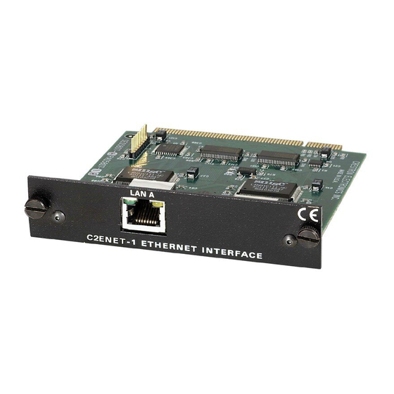
(including the FTP site). Physical Description The C2ENET-1 and C2ENET-2 (refer to graphics below and on next page) are printed circuit boards (PCBs) fastened to aluminum faceplates. The cards are designed to be installed in a Z-BUS expansion slot on the 2-Series control systems. -
Page 7: Industry Compliance
LINK STATUS LED (GREEN) Industry Compliance As of the date of manufacture, the C2ENET-1/-2 has been tested and found to comply with specifications for CE marking and standards per EMC and Radiocommunications Compliance Labelling (N11785). NOTE: This device complies with part 15 of the FCC rules. Operation is subject to... -
Page 8: Ethernet Cable Connections
Connection to PC If the system is connected directly to a personal computer (PC) Ethernet card, make sure that the cable between the C2ENET-1/-2 is a crossover type. RJ-45 Pinouts The following illustrates pinouts for a straight through and crossover RJ-45 Ethernet cables. -
Page 9: Setup
Installation CAUTION: The C2ENET-1/-2 and the control system contain electro-static discharge (ESD) sensitive devices. Crestron recommends that you wear a grounding strap to avoid damaging the card and/or the control system. AV2 (AV2 with Card Cage & PRO2 Similar) Z-BUS Expansion Slot Example PAC2 Z-BUS Expansion Slot Example Operations &... -
Page 10: Ip Setup
IP numbers using Viewport. The external router is not configured using Viewport. IP Setup 6 • 2-Series Ethernet Interface Expansion Cards: C2ENET-1 & C2ENET-2 3. Remove the Ethernet card from its packaging. 4. On the Ethernet card, make sure the thumbscrews are extended outward, align the card with the card guides in the open Z-BUS expansion slot, and slide the card into slot. - Page 11 5. At the prompt, type PING and the IP number. Press Enter. Example: PING 192.168.1.102 6. Open the Crestron Viewport and select Functions | Set Control System IP Information from the main menu. The “Ethernet Configuration” window opens (refer to following graphics).
- Page 12 The network addresses of LAN A and LAN B cannot be the same. For example, if the same subnet mask is applied to both IP addresses and the resulting network 8 • 2-Series Ethernet Interface Expansion Cards: C2ENET-1 & C2ENET-2 Crestron C2ENET-1/-2...
- Page 13 Crestron C2ENET-1/-2 address is 192.168.1.0, then an error message will be generated. Refer to the “e- Control Hardware Configuration” section within the latest version of the Crestron e-Control For Dynamic IP Addressing “Ethernet Configuration” Window If applicable, enter the domain in the Domain field. This is necessary only if you are configuring DHCP on an Ethernet connection to a control system that currently has a static address.
- Page 14 Then enter the IP address or fully qualified domain name of the control system. 10 • 2-Series Ethernet Interface Expansion Cards: C2ENET-1 & C2ENET-2 If the DHCP server provides the address for the DNS server, it is not necessary to enter these values.
-
Page 15: Verify Communication
Remote | TCP/IP | Connect from the Taskbar. The “Crestron Viewport TCP/IP Connect” window appears. 2. Enter the IP number you entered earlier and click Connect. The Crestron Viewport confirms the connection. 2-Series Ethernet Interface Expansion Cards: C2ENET-1 & C2ENET-2 • 11... -
Page 16: Setting A Control System Ethernet Password
Viewport Set TCP/IP Control Password option “Enter New Password” Window 12 • 2-Series Ethernet Interface Expansion Cards: C2ENET-1 & C2ENET-2 1. In Viewport, select Functions | Set TCP/IP Console Password. The “Enter New Password” window opens (refer to subsequent graphic). -
Page 17: Network Address Translation For Crestron 2-Series Control Systems
Network Address Translation (NAT) is a method of connecting multiple computers on an internal network to the Internet (or any other IP network) using one publicly visible IP address. Current implementation for the Crestron 2-Series control systems includes a combination of the Network Address Port Translator protocol (NAPT) and Bi-Directional NAT. -
Page 18: Programming Software
Answers to frequently asked questions (FAQs) can be viewed in the Online Help section of the Crestron website (www.crestron.com). To post your own question or view questions you have submitted to Crestron’s True Blue Support, log in at http://www.crestron.com/accounts/login.asp. First-time users will need to establish a user account. - Page 19 IP table. The second method is to use the Crestron Viewport. This method is especially useful on site if you want to change one or more IP addresses without changing the program.
-
Page 20: Tcp/Ip Client And Tcp/Ip Server Symbols
2-Series Ethernet Interface Expansion Cards another control system. Here the IP table of the PRO2 must contain just one entry for the master control system. Refer to the “Creating an IP Table” section within the latest version of the Crestron e-Control Example Program An example program for the C2ENET-1/2 is available from the Crestron website (www.crestron.com). - Page 21 Operations & Installation Guide – DOC. 5962B 2-Series Ethernet Interface Expansion Cards Analog Value Connection Status Not connected Waiting for connection Connected Connection failed Connection broken remotely Connection broken locally Performing DNS lookup DNS lookup failed 2-Series Ethernet Interface Expansion Cards: C2ENET-1 & C2ENET-2 • 17...
-
Page 22: Programming With Vt Pro-E
AV2/PRO2 allots 2.5 MB of memory for “user files” such as Web pages, mailbox, and the compiled SPZ file. Web pages are loaded in the AV2/PRO2 using Viewport. Refer to the “Uploading Web Pages” section within the latest version of the Crestron e-Control 18 •... -
Page 23: Problem Solving
Control system runs Potential virus on Web slow or crashes on port 80. LAN. 2-Series Ethernet Interface Expansion Cards: C2ENET-1 & C2ENET-2 • 19 Corrective Action Follow installation procedures in this guide. Verify proper connection at Ethernet port. -
Page 24: Further Inquiries
Therefore, please check Crestron’s website (http://www.crestron.com/downloads/software_updates.asp) for the latest version of firmware. Not every product has a firmware upgrade, but as Crestron improves functions, adds new features, and extends the capabilities of its products, firmware upgrades are posted. If you have questions regarding upgrades procedures, contact Crestron customer service. -
Page 25: Software License Agreement
This Agreement may only be modified by a writing signed by an authorized officer of Crestron. Updates may be licensed to You by Crestron with additional or different terms. This is the entire agreement between Crestron and You relating to the Software and it supersedes any prior representations, discussions, undertakings, communications or advertising relating to the Software. -
Page 26: Governing Law
(90) days from the date of receipt, and (b) that any hardware accompanying the Software will be subject to its own limited warranty as stated in its accompanying written material. Crestron shall, at its option, repair or replace or refund the license fee for any Software found defective by Crestron if notified by you within the warranty period. -
Page 27: Return And Warranty Policies
CRESTRON shall not be liable to honor the terms of this warranty if the product has been used in any application other than that for which it was intended, or if it has been subjected to misuse, accidental damage, modification, or improper installation procedures. -
Page 28: Glossary Of Terms
Glossary of Terms 2-SERIES CONTROL SYSTEM Crestron 2-Series control systems include the AV2 and PRO2. Consult the latest Crestron Product Catalog for a complete list of 2-Series control systems that are Ethernet-enabled directly or via a C2ENET-1/-2 Ethernet card. CRESNET ID Cresnet ID, a unique identity code ranging from 03 to FE (in hexadecimal), is given to all devices that communicate using the Cresnet network protocol. -
Page 29: Network Address
Crestron C2ENET-1/-2 NETWORK ADDRESS A network address is a pattern of bits in IP address format that is shared by all network devices on a given local network. For example, network address 192.168.2.0 describes the local network where all devices have an IP address of 192.168.2.x, where x is any value from 1 to 254. - Page 30 2-Series Ethernet Interface Expansion Cards Crestron C2ENET-1/-2 This page intentionally left blank. 26 • Glossary of Terms Operations & Installation Guide – DOC. 5962B...
- Page 31 Crestron C2ENET-1/-2 2-Series Ethernet Interface Expansion Cards This page intentionally left blank. Glossary of Terms • 27 Operations & Installation Guide – DOC. 5962B...
- Page 32 Crestron Electronics, Inc. Operations & Installation Guide – DOC. 5962B 15 Volvo Drive Rockleigh, NJ 07647 10.04 Tel: 888.CRESTRON Fax: 201.767.7576 Specifications subject to www.crestron.com change without notice.