Table of Contents
Advertisement
Quick Links
Advertisement
Table of Contents

Related Manuals for Crestron CNXRY-16


Summary of Contents for Crestron CNXRY-16
- Page 1 Crestron CNXRY-16 CNX Relay Output Expansion Card Operations Guide...
-
Page 2: Table Of Contents
Contents CNX Relay Output Expansion Card: CNXRY-16 Description... 1 Functional Description ... 1 Physical Description... 1 Leading Specifications... 2 Setup ... 2 Installation ... 2 Preparation for Use... 3 Programming with SIMPL Windows ... 3 How the Program Works... 4 How to Create the Program ... -
Page 3: Cnx Relay Output Expansion Card: Cnxry-16
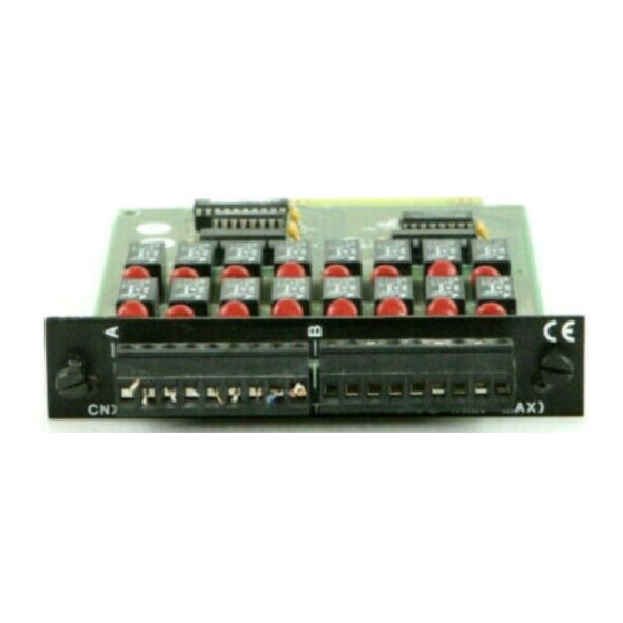
CNXRY-16 Schematic Physical Description The CNXRY-16, shown below, is a circuit board fastened to an aluminum faceplate. The card is manufactured to easily fit into an unoccupied slot in a Crestron CNX Generation Control System. CNXRY-16 Faceplate The faceplate contains two identical male, 9-pin connectors. There are eight relay pins and one common ground pin per connector. -
Page 4: Leading Specifications
CE marking. Setup Installation Items required to install the CNXRY-16 are already attached to the unit. The only tools required are a Phillips tip screwdriver and a grounding strap. Follow the assembly procedure below. CAUTION: The CNXRY-16 contains electrostatic sensitive devices (ESD);... -
Page 5: Preparation For Use
Preparation for Use Connections are made to the 16 normally open, isolated relays of the CNXRY-16. The connectors are labeled A1 through A8 and B1 through B8. Refer to a sample hookup diagram below and aside from reapplying power to the control system last, complete the connections in any order. -
Page 6: How The Program Works
For this example, add a CNXRY-16 to slot #1 of the CNMSX-PRO. Also add a LC-1500 to the system; its NET ID must be set to 03, shown on the next page. - Page 7 Manager Use the Programming Manager workspace in SIMPL Windows to select symbols and assign their respective signals. For this example, a touchpanel and CNXRY-16 symbols were added automatically when the devices were added to the system in the Configuration Manager workspace. Expand the Network Modules folder and double click on the touchpanel for a detail view (alternatively CTRL+D or drag and drop into Detail View).
- Page 8 Expand the Central Control Modules folder and double click on the CNXRY-16 for a detail view (alternatively CTRL+D or drag and drop into Detail View). Assign signals as shown below. Graphical Detail View of CNXRY-16 in SIMPL Windows’ Programming Manager Expand the Logic folder and double click on both Interlock icons for a detail view (alternatively CTRL+D or drag and drop into Detail View).
-
Page 9: Problem Solving
CNXRY-16 does not function. Further Inquiries If after reviewing this Operations Guide for the CNXRY-16, you cannot locate specific information or have questions, please take advantage of Crestron's award winning customer service team by calling: Operations Guide - Doc. 8122... -
Page 10: Return And Warranty Policies
CRESTRON shall not be liable to honor the terms of this warranty if the product has been used in any application other than that for which it was intended, or if it has been subjected to misuse, accidental damage, modification, or improper installation procedures. - Page 11 CRESTRON This page intentionally left blank. CNX Relay Output Expansion Card: CNXRY-16 • 9 Operations Guide - Doc. 8122...
- Page 12 Crestron Electronics, Inc. Operations Guide – DOC. 8122 15 Volvo Drive Rockleigh, NJ 07647 09.98 Tel: 888.CRESTRON Fax: 201.767.7576 Specifications subject to www.crestron.com change without notice.