Table of Contents
Advertisement
Quick Links
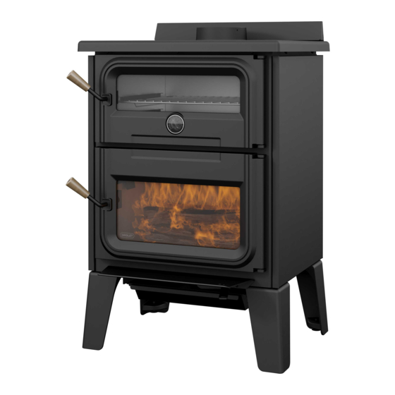
Installation and Operation Manual
BISTRO WOOD BURNING
COOKSTOVE
(DB04815 model)
MOBILE
HOME
Security test made according to
regulations ULC S627 and UL 1482
by an accredited laboratory.
ISO PAGE 1
CONTACT LOCAL BUILDING OR FIRE OFFICIALS ABOUT RESTRICTIONS AND INSTALLATION INSPECTION REQUIREMENTS
IN LOCAL AREA.
READ THIS ENTIRE MANUAL BEFORE INSTALLATION AND USE OF THIS WOOD STOVE. FAILURE TO FOLLOW THESE INSTRUCTIONS
COULD RESULT IN PROPERTY DAMAGE, BODILY INJURY OR EVEN DEATH.
U.S. ENVIRONMENTAL PROTECTION AGENCY: THIS UNIT IS NOT A CERTIFIED RESIDENTIAL WOOD HEATER. THE PRIMARY USE
FOR THIS UNIT IS FOR COOKING OR BAKING.
READ AND KEEP THIS MANUAL FOR REFERENCE
Printed in Canada
45251A
Advertisement
Table of Contents

Related Manuals for Drolet DB04815


Summary of Contents for Drolet DB04815
- Page 1 Installation and Operation Manual BISTRO WOOD BURNING COOKSTOVE (DB04815 model) MOBILE HOME Security test made according to regulations ULC S627 and UL 1482 by an accredited laboratory. ISO PAGE 1 CONTACT LOCAL BUILDING OR FIRE OFFICIALS ABOUT RESTRICTIONS AND INSTALLATION INSPECTION REQUIREMENTS IN LOCAL AREA.
- Page 3 It is also highly recommended to register the warranty online at https://www.drolet.ca/en/warranty/warranty-registration/ Registering the warranty will help to quickly find the information needed on the unit. Installation and operation manual - Bistro woodburning cookstove...
-
Page 4: Table Of Contents
TABLE OF CONTENTS CERTIFICATION PLATE ........................ PART A - OPERATION AND MAINTENANCE ................1. Safety Information ......................... 7 2. General information ....................... 9 Specifications ....................... 9 Cookstove Dimensions ....................10 3. Cookstove operation ......................12 Components use ......................12 Gas path ........................15 4. - Page 5 PART B - INSTALLATION ......................7. General Information ......................37 Security ........................37 Regulations Governing the Installation of the Cookstove ..........38 Cookstove Positioning ....................38 Location of the Certification Label .................38 8. Clearances to Combustible Material .................. 39 Floor Protection ......................42 Clearances Reduction to the Walls and the Ceiling ............43 Clearances for Shield Installation ...................45 9.
-
Page 6: Certification Plate
CERTIFICATION PLATE Page 6 Installation and operation manual - Bistro woodburning cookstove... -
Page 7: Part A - Operation And Maintenance
PART A - OPERATION AND MAINTENANCE U.S. ENVIRONMENTAL PROTECTION AGENCY: THIS UNIT IS NOT A CERTIFIED RESIDENTIAL WOOD HEATER. THE PRIMARY USE FOR THIS UNIT IS FOR COOKING OR BAKING. 1. Safety Information • Operate only with doors fully closed. If door is left partly open, gas and flame may be drawn out of the opening, creating risks from both fire and smoke. - Page 8 • DO NOT USE CHEMICALS OR FLUIDS TO START THE FIRE. • DO NOT BURN GARBAGE OR FLAMMABLE LIQUIDS SUCH AS GASOLINE, NAPHTHA, FUEL OIL, ENGINE OIL, KEROSENE, CHARCOAL LIGHTER FUEL, SIMILAR LIQUIDS, OR AEROSOLS TO START, REVIVE OR NEAR THE FIRE. KEEP ALL SUCH LIQUIDS WELL AWAY FROM THE HEATER WHILE IT IS IN USE.
-
Page 9: General Information
2. General information Specifications Model Bistro woodburning cookstove (DB04815) Fuel Type Dry Cordwood Recommanded log length 16" (406 mm) Maximum log length 20" (508 mm) east-west orientation Flue outlet diameter 6 in (150 mm) Chimney diameter 6 in (150 mm) -
Page 10: Cookstove Dimensions
Cookstove Dimensions 26 7/8" 26 7/8" 683mm 683mm 13 7/16" 13 7/16" 342mm 342mm 26 7/8" 683mm 13 7/16" 342mm 6" 6" 153mm 153mm 6" 153mm 26 3/8" 26 3/8" 670mm 670mm 22 3/8" 22 3/8" Figure 1: Top view 568mm 568mm 20 7/16"... - Page 11 2.2.1 Combustion Chamber Dimensions 9" 9" 228mm 9" 228mm 17 1/2" 228mm 17 1/2" 444mm 17 1/2" 444mm 444mm Figure 4: Door opening 5/16" 5/16" 3/16" 3/16" 5/16" 3/16" 11 7/8" 11 7/8" 21" 21" 301mm 11 7/8" 301mm 533mm 21"...
-
Page 12: Cookstove Operation
3. Cookstove operation Components use Cooking with a wood-burning cookstove is an art that requires several attempts to get to know and control the appliance. Many factors can influence how the cookstove will heat the oven and the cooking surface. Among them, the type of fuel used and its quality, the size of the logs and when to load before cooking. - Page 13 3.1.1 Oven FIGURE 5 FIGURE 5 Figure 8: Oven door closed Figure 9: Oven door open FIGURE 6 The cooker has a stainless steel oven to cook or bake food. The panoramic glass of the oven door allows you to watch your meal without having to open the door. During cooking, keep the oven door closed to maintain a constant temperature.
- Page 14 3.1.2 Cast iron cooking surface FIGURE 7 Figure 10: Cast iron cooking surface It is not recommended to cook food directly on the cast iron top, as the paint used is not food grade. The cast iron cooking surface on the top of the range is designed to provide intense heat to allow food to be cooked.
-
Page 15: Gas Path
Gas path Figure 11: Gas path FIGURE 8 The gas path is in fact the circuit followed by the hot gases emitted by burning wood. This circuit is used to heat the stainless steel oven and the cast iron cooking surface. The primary air supply provided by the pilot feeds the wood combustion. -
Page 16: Combustibles
4. Combustibles Good firewood has been cut to the correct length for the stove, split to a range of sizes and stacked in the open until its moisture content is down to 15% to 20%. DO NOT BURN: • GARBAGE; •... -
Page 17: Log Length
Log Length Logs should be cut at least 1" (25 mm) shorter than the firebox so they fit in easily. Pieces that are even slightly too long makes loading the stove very difficult. The most common standard length of firewood is 16" (400 mm). Piece Size Firewood dries more quickly when it is split. -
Page 18: Efficient Wood Combustion
Here are some facts to consider in estimating drying time: − Firewood bought from a dealer is rarely dry enough to burn, so it is advisable to buy the wood in spring and dry it yourself; − Drying happens faster in dry weather than in a damp climate; −... -
Page 19: First Use
First Use Two things happen when burning the first few fires; the paint cures and the internal components are conditioned. As the paint cures, some of the chemicals vaporize. The vapors are not poisonous, but they smell bad. Fresh paint fumes can also trigger false alarms in smoke detectors. When lighting the heater for the first few times, it may be wise to open doors and windows to ventilate the house. -
Page 20: Combustion Cycles
It is possible to use ragged paper but it may not hold in place since it tends to roll while it is burning. The best is to wrap a sheet on itself, grab the ends of the roll and make a knot. Use four or five sheets of paper tied together and put them on top and around the kindling. -
Page 21: Rekindling A Fire
Rekindling a Fire Generally, when you need to cook, it is time to reload. Remove excess ash from the front of the firebox and bring the ashes forward. Place a new load of wood on, and at the back of the embers. - Page 22 The control of the primary and secondary air inlet is simultaneous and is done with a single regulation control, located under the combustion chamber door. The optimum regulation of the air inlet can vary according to various factors, such as the chimney flue, the temperature of the cookstove and, the quality of the firewood (moisture, size and shape).
-
Page 23: Maintenance
6. Maintenance This cookstove will give many years of reliable service if used and maintained properly. Some of the internal components of the firebox, such as vermiculite and baffle will wear over time under intense heat. Defective parts should always be replaced with original parts. Firing each load hot to begin a cycle will not cause premature deterioration of the cookstove. -
Page 24: Grills And Cast Iron Cooking Surface
Grills and cast iron cooking surface Clean the grills with a brush and mild soap. To clean the cast iron cooking surface, wipe it with a soft and damp cloth. Do not clean the surface when it is hot. If rust or scratches appear, follow the instructions in section 6.4 Cleaning and painting to repair the surface. -
Page 25: Glasses
Glasses The cookstove has two glasses to maintain. The combustion chamber glass has a gasket while the furnace does not. 6.6.1 Cleaning Under normal conditions, the door glass should stay relatively clear. If the firewood is dry enough and the operating instructions in this guide are followed, a whitish, dusty deposit will form on the inner surface of the glass after a week or so of use. - Page 26 6.6.2 Replacement The glass used is a ceramic glass, 5/32" (4 mm) thick, tested to reach temperatures up to 1400º F. If the glass breaks, it must be replaced with one having the same specification. To remove or replace the glass (D): THE IMAGES SHOWN ARE FOR GUIDANCE ONLY AND MAY BE DIFFERENT FROM YOUR PRODUCT, BUT THE ASSEMBLY REMAINS THE SAME.
- Page 27 6.6.3 Gasket The glass gasket is flat, adhesive-backed, woven fibreglass. The gasket must be centred on the edge of the glass. Follow the steps of the previous section to remove the glass. Remove the old gasket and clean the glass thoroughly. Peel back a section of the paper covering the adhesive and place the gasket on a table with the adhesive side Stick the end of the gasket to the middle of one edge,...
- Page 28 6.6.6 Adjustment of the combustion chamber door In order for the stove to burn at its best efficiency, the door must provide a perfect seal with the firebox. Therefore, the gasket should be inspected periodically to check for a good seal. The gasket seal may be improved with a simple latch mechanism adjustment: Remove the split pin by pulling and turning it using pliers.
- Page 29 6.6.7 Door Alignment To align, open the door and loosen the pressures screws located on the lower and upper hinges of the door using a 3/32” Allen key to free the adjustable hinge rods. Figure 15: Release eccentric hinges Figure 16: Adjust eccentric hinges Using a flat screwdriver, turn the adjustable hinge rods in the direction shown to adjust the doors.
- Page 30 6.6.8 Gasket It is important to replace the gasket with another having the same diameter and density to maintain a good seal. Remove the door and place it face-down on something soft like a cushion of rags or a piece of carpet. Remove the old gasket from the door.
-
Page 31: Decorative Panels
Decorative Panels To remove the decorative panel (A), remove the screws (B) and push forward on the panel to unhook it from the bracket (C). Installation and operation manual - Bistro woodburning cookstove Page 31... - Page 32 Fresh Air Intake Kit Installation The installation of a fresh air intake kit (A) requires an insulated fresh air intake pipe (B) HVAC type (must meet ULC S110 or UL 181 class 0 or class 1), sold separately. It is mandatory to install the fresh air intake in a mobile home. Refer to air intake kit installation instructions for more details.
-
Page 33: Air Tubes And Baffle Installation
Air Tubes And Baffle Installation Starting with the rear tube, lean and insert the right end of the secondary air tube into the rear right channel hole. Then lift and insert the left end of the tube into the rear left channel. Align the notch in the left end of the tube with the key of the left air channel hole. -
Page 34: Handles Installation
Note that secondary air tubes (B) can be replaced without removing the baffle board (A) and that all tubes are not necessarely identical (look at the part number on the tube). 6.10 Handles installation Insert, in order, the natural wood handle (A), the washer (B) and the screw (C) on the handle rod of each door. -
Page 35: Mobile Home Installation
6.11 Mobile Home Installation THE IMAGES SHOWN ARE FOR GUIDANCE ONLY AND MAY BE DIFFERENT FROM YOUR PRODUCT, BUT THE ASSEMBLY REMAINS THE SAME. For a stove on legs, install a plate (L) on each leg and screw it in place with the proper hardware (M). - Page 36 6.12.1 Frequency It is not possible to predict how much or how quickly creosote will form in the chimney. It is important, therefore, to check the build-up in the chimney monthly until the rate of creosote formation is determined. Even if creosote forms slowly in the system, the chimney should be cleaned and inspected at least once each year.
- Page 37 6.12.3 Chimney Fire Regular chimney maintenance and inspection can prevent chimney fires. If you have a chimney fire, follow these steps: Close the stove door and the air intake control; Alert the occupants of the house of the possible danger; If you require assistance, alert the fire department;...
- Page 38 Page 38 Installation and operation manual - Bistro woodburning cookstove...
-
Page 39: Part B - Installation
PART B - INSTALLATION 7. General Information Security • Read this manual completely before installing the cookstove. It is important to fully respect the installation instructions. If the cookstove is not correctly installed, it could result in a fire, bodily injuries or even death. -
Page 40: Regulations Governing The Installation Of The Cookstove
Regulations Governing the Installation of the Cookstove In Canada, the CSA B365 Installation Code for Solid Fuel Burning Appliances and Equipment is to be followed in the absence of local code requirements. In the USA, the ANSI NFPA 211 Standard for Chimneys, Fireplaces, Vents and Solid Fuel-Burning Appliances is to be followed in the absence of local code requirements. -
Page 41: Clearances To Combustible Material
8. Clearances to Combustible Material The clearances given in this section have been established following test results in accordance with the procedures described in the standards ULC S627 (Canada) and UL 1482 (USA). When this cookstove is installed respecting the indicated minimum clearances or more, the flammable surfaces won’t overheat during normal or even abnormal usage. - Page 42 48" 72" 183 cm Flush 48" 36" 122 cm 92 cm Figure 21: Clearances - Top Figure 22: Clearances - Side Figure 23: Clearances - Corner Page 42 Installation and operation manual - Bistro woodburning cookstove...
- Page 43 APPLIANCE CLEARANCES (INSTALLATION APPLIANCE CLEARANCES (INSTALLATION WITH SINGLE WALL PIPE CONNECTOR) WITH DOUBLE WALL PIPE CONNECTOR) Canada Canada 15" (381 mm) 15" (381 mm) 6" (152 mm) 6" (152 mm) 15" (381 mm) 15" (381 mm) 15" (381 mm) 15" (381 mm) 7.5"...
-
Page 44: Floor Protection
Floor Protection This stove is designed to prevent the floor from overheating. However, it must be placed on a non-flammable surface to protect the floor from hot embers that may fall during loading. Any type of tile will require a continuous non combustible sheet beneath to prevent the possibility of embers falling through to the combustible floor if cracks or separation should occur in the finished surface. -
Page 45: Clearances Reduction To The Walls And The Ceiling
Clearances Reduction to the Walls and the Ceiling It is often desired to use as little space as possible when installing cookstove. To do this, it is possible to reduce the clearances safely and install the cookstove closer to the walls by permanently installing a heat shield between the cookstove and the flammable material. - Page 46 Table 1 : Clearances Reduction Percentages Table CLEARANCES MAY BE REDUCED BY THESE PERCENTAGES TYPE OF SHIELD SIDES AND REAR TOP (CEILING) CAN /USA CAN /USA MIN. MIN. Sheet metal, a minimum of 24 gauge (0.61 mm) in thickness , spaced out at least 25 mm (1 in)* 12 in 18 in by non-combustible spacers...
-
Page 47: Clearances For Shield Installation
Clearances for Shield Installation Minimum clearance between the top of 833 mm the appliance and the (32 13/16") unprotected ceiling Shield extension above 500 mm appliance (20") USA 25 mm (1") Minimum space behind the Can. 21 mm shield (7/8") USA 25 mm (1") Clearance at the bottom of Can. - Page 48 8.3.1 Mobile Home It is strictly forbidden to install a unit with a single wall pipe in a mobile home. APPLIANCE CLEARANCES WITH DOUBLE DISTANCES FROM PIPE CONNECTOR WALL PIPE CONNECTOR WITH DOUBLE WALL PIPE CONNECTOR Canada Canada 6" (152 mm) 6"...
-
Page 49: Evacuation System
8.3.2 Mobile Home With Heat Shield APPLIANCE CLEARANCES WITH DOUBLE DISTANCES FROM PIPE CONNECTOR WALL PIPE CONNECTOR WITH DOUBLE WALL PIPE CONNECTOR Canada Canada 3" (76 mm) 3" (76 mm) 6.25" (159 mm) 6.25" (159 mm) 3" (76 mm) 3" (76 mm) 8.75"... - Page 50 9.2.1 Factory-Built Metal Chimneys These sometimes referred ‘high temp’ chimneys because they have the specific characteristics to withstand temperatures that can be created by wood burning stoves. Factory- built chimneys are tested as a system with all the necessary components for installation. The instructions provided with the chimney by its manufacturer are the only reliable source of installation guidelines.
-
Page 51: Minimum Chimney Height
9.2.3 Masonry Chimneys The stove may also be connected to a masonry chimney, provided the chimney complies with the construction rules found in the building code enforced locally. The chimney must have either a clay liner or a suitably listed stainless steel liner. If the masonry chimney has a square or rectangular liner that is larger in cross-sectional area than a round 6"... - Page 52 Venting systems that rise straight up from the stove flue collar provide the best performance. Chimneys that rise inside the warm space of the house tend to provide a small amount of draft even when there is no fire burning. This means that when a fire is lit, the smoke goes up the chimney and strong draft build quickly as the chimney flue warms up.
-
Page 53: Installing The Chimney Connector
Installing the Chimney Connector The chimney connector is the single or double wall pipe installed between the stove flue collar and the chimney breech. Single wall pipe components are available from most hardware and bu ilding supply stores. These components are not usually tested to a particular standard and certified as compliant. - Page 54 • The assembly should be as short and direct as possible between the stove and chimney. The use of two 45 degree elbows is often preferable to a single 90 degree elbow because less turbulence is created in the exhaust flow and they result in less horizontal run. •...
-
Page 55: Installation Of Double Wall Chimney Connector
A vortex double wall connector, with its vented stove adapter (VOD0290), is recommended for this type of installation. Consult www.drolet.ca for more details. Other brands of double wall connectors are adequate as long as they offer the option of a vented double wall stove adapter. -
Page 56: Combustion Air
Combustion Air For the cookstove draft to work correctly, the room must have an outside or fresh air inlet, with a minimum of 5" diameter, from the house exterior to the room, that is at least sufficient to replenish the volume of air that comes out of the chimney flue. In well insulated houses an air inlet must be fitted through the outer wall that is not exposed to the prevailing winds, depending on the surrounding conditions of the house. -
Page 57: Conventional House
11.2 Conventional House The safest and most reliable supply of combustion air for a wood stove is from the room in which it is installed. Room air is already preheated so it will not chill the fire, and its availability is not affected by wind pressures on the house. -
Page 58: Troubleshooting
Troubleshooting PROBLEM POSSIBLE CAUSES SOLUTION • Draft too low • Check that all the pipes are clean. • Bad air intake adjustment • Modify the chimney: increase the height Oven window • Too much combustible in the or check surrondings. or combustion cookstove. -
Page 59: Parts List
Parts List DETAIL E DETAIL C Installation and operation manual - Bistro woodburning cookstove Page 59... - Page 60 IMPORTANT: THIS IS DATED INFORMATION. When requesting service or replacement parts for your unit, please provide the model number and the serial number. We reserve the right to change parts due to technology upgrade or availability. Contact an authorized dealer to obtain any of these parts.
- Page 61 Item Description 21635 17" X 20 5/16" X 1/2" INSULATION PL74534 INSULATING PROTECTIVE 30782 HEX FLANGE NUT SERRATED 1/4-20 STAINLESS 18-8 31232 1/4"-20 X 1" SET SCREW SE24361 TOP ASSEMBLY PL24365 CAST IRON SPIGOT PAINTED PL36899 DOUBLE WALL ADAPTOR 30024 1/4-20 X 1"...
-
Page 62: Bistro Cooking Stove Limited Lifetime Warranty
90 days *Subject to limitations above. **Picture required. Shall your unit or a components be defective, contact immediately your DROLET dealer. To accelerate processing of your warranty claim, make sure to have on hand the following information when calling: ... - Page 63 NOTES :...
- Page 64 Resale is strictly prohibited. The manufacturer may update St-Augustin-de-Desmaures (Québec) Canada this document from time to time and cannot be responsible G3A 2H3 for problems, injuries, or damages arising out of the use 418-908-8002 of information contained in any document obtained from www.drolet.ca/en/ unauthorized sources. tech@sbi-international.com...