Table of Contents
Advertisement
Quick Links
OWNER'S MANUAL
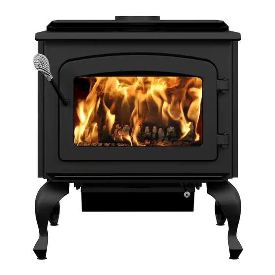
ESCAPE 1800 EPA WOOD STOVE
MODELS DB03100, DB03110, DB03115, & DB03116
WOOD STOVES CERTIFIED ACCORDING TO US ENVIRONMENTAL PROTECTION
AGENCY PHASE II
Verified and tested following
ULC S627 and UL 1482 Standards
by:
Manufactured by : STOVE BUILDER INTERNATIONAL INC.
250, de Copenhague, Saint-Augustin-de-Desmaures (Québec), Canada, G3A 2H3
Telephone : (418) 878-3040
Fax : (418) 878-3001
www.drolet.ca
READ AND KEEP THIS MANUAL FOR REFERENCE
45228
Advertisement
Table of Contents

Related Manuals for Drolet ESCAPE 1800 DB03100


Summary of Contents for Drolet ESCAPE 1800 DB03100
- Page 1 WOOD STOVES CERTIFIED ACCORDING TO US ENVIRONMENTAL PROTECTION AGENCY PHASE II Verified and tested following ULC S627 and UL 1482 Standards Manufactured by : STOVE BUILDER INTERNATIONAL INC. 250, de Copenhague, Saint-Augustin-de-Desmaures (Québec), Canada, G3A 2H3 Telephone : (418) 878-3040 Fax : (418) 878-3001 www.drolet.ca...
- Page 2 The instructions pertaining to the installation of your wood stove in North America comply with ULC-S627 and UL-1482 standards. Read this entire manual before you install and use your new stove. If this stove is not properly installed, a house fire may result. To reduce the risk of fire, follow the installation instructions.
-
Page 3: Table Of Contents
1.1.1 Ash drawer assembly for DB03115 model ... 6 1.1.2 Legs and ash drawer assembly for DB03116 model ... 6 POSITIONING THE STOVE ... 8 CLEARANCES ... 8 1.3.1 REDUCED CLEARANCES ... 10 FLOOR PROTECTOR ... 14 TIPS ON WOOD HEATING ... 15 SECTION 2.0 CHIMNEY (FLUE SYSTEM) ... - Page 4 GASKETING ... 43 ASH REMOVAL USING THE ASH DRAWER ... 43 CHIMNEY (FLUE) CLEANING ... 44 BAFFLE INSTALLATION FOR ESCAPE 1800 MODEL ... 44 SECONDARY AIR TUBE REPLACEMENT ... 46 SECTION 5.0 SPECIFICATIONS ... 47 DROLET LIMITED LIFETIME WARRANTY ... 48...
-
Page 5: Section 1.0 - Installation
SECTION 1.0 - INSTALLATION When installed and operated as described in these instructions, the Escape 1800 EPA wood stove is suitable for use as a freestanding wood stove in residential installations. The Escape 1800 EPA wood stove is not intended for installation in a bedroom or a mobile home. -
Page 6: Ash Drawer Assembly For Db03115 Model
Please note that only DB03115 and DB03116 models require this additional assembly. 1.1.1 Ash drawer assembly for DB03115 model Before positioning the wood stove, it is suggested to assemble the ash drawer on DB03115 model as shown below : 1.1.2 Legs and ash drawer assembly for DB03116 model Before positioning the wood stove, it is suggested to perform the following steps for the legs and ash drawer assembly for DB03116 model. - Page 7 Then, install the legs using the bolts (B) supplied in a big in the firebox as shown below : The last step consists of installing the ash drawer. To do so, use the guides designed for this purpose located under the unit as shown below :...
-
Page 8: Positioning The Stove
84" (2134 mm). Clearances to any combustibles when measured directly from the front of the stove must be a minimum of 48" (1219 mm). The stove must also be placed so as to maintain the minimum clearances to combustible walls specified for each type of connector used. - Page 9 Figure 1.3 Clearances to combustible materials...
-
Page 10: Reduced Clearances
3" (76 mm) between the top of the shield and the ceiling must be respected to allow vertical air circulation behind the shield. The shield must extend 20" (500 mm) above the stove top and 18" (450mm) to each side of the stove (see Graphic 1). - Page 11 Graphic 1 A- Clearance to combustible material with no protection. B- 500 mm (20 po.) minimum; C- 25 mm (1 po.) minimum; D- Between 25 mm (1 po.) and 75 mm (3 po.) ; E- 75 mm (3 po.) minimum; F- 450 mm (18 po.) minimum.
- Page 12 A- 25 mm (1 po.) minimum; 1- Combustible wall ; 2- Non-combustible spacer; 3- 0.61 mm (0.024") sheet metal. A- 25 mm (1 po.) minimum; 1- Combustible wall; 2- Non-combustible spacer; 3- Fire-proof support; 4- Ceramic tile or equivalent non-combustible material. _____________________________________________________________________________ A- 25 mm (1 po.) minimum;...
- Page 13 A- 25 mm (1 po.) minimum; 1- Combustible wall; 2- Non-combustible spacer; 3- Brick. A- 25 mm (1 po.) minimum; 1- Combustible wall; 2- Non-combustible spacer; 3- 0.61 mm (0.024") sheet metal; 4- Brick. Graphic 5 Graphic 6...
-
Page 14: Floor Protector
FLOOR PROTECTOR If the stove is to be installed on top of a combustible floor, it must be guarded by a non-combustible material extending at least 18” (300mm) from the front and 8” (200mm) from the sides and the back of the firebox., as shown in Figure 1.4 below. -
Page 15: Tips On Wood Heating
The chimney is the engine that drives the wood-heating system. Use a chimney that is UL-listed, with an inner diameter to match the stove’s outlet collar (6” for all Drolet wood stoves);... -
Page 16: Section 2.0 Chimney (Flue System)
• Do not cut rafters or ceiling joists without first consulting a building official to ensure structural integrity is not compromised. Your wood stove may be hooked up with a factory built or masonry chimney. If you are using a factory built chimney, it must comply with UL103 (USA) or ULCS629 (Canada) standards. It must therefore be a 6”... - Page 17 Round chimneys are the most efficient. The interior diameter of the chimney should be identical to the stove's smoke exhaust. A chimney which is too small may cause draft problems, since it may not have the required volume to properly evacuate the quantity of smoke resulting from the combustion.
-
Page 18: Step By Step Installation Of Your Factory-Built Chimney
North American retailers of wood stoves and related heating accessories. Wall support system If your chimney must rise along an outside wall, you need to connect it to your stove through an adjacent wall. For this type of installation, the following items are normally required : Chimney •... - Page 19 Typical installation through the wall FIGURE 2.2.1 (A) Typical installation through the wall...
- Page 20 1- Start by positioning your stove where you would like it to go, taking into account the minimum clearances to combustible material. You will then be able to determine where the chimney will pass through the wall. You will probably have to adjust the stove position slightly to ensure that your chimney will run between the studs.
- Page 21 The chimney must extend at least 3 inches into the living space where it attaches to the stove pipe. 5- You can now install the wall support. Simply slide the wall support up to the tee, ensuring that the adapter on the support engages with the female coupler on the bottom of the tee.
- Page 22 9- You are now ready to connect your chimney to your stove. Simply install the inter-connecting stove pipe between the stove pipe adapter and the stove. You can follow the instructions in the following section (section 2.3) of this manual called « CHIMNEY CONNECTOR».
- Page 23 Ceiling support system If your chimney must rise inside the house and go through the ceiling, you need to connect it to your stove at the ceiling level. For this type of installation, the following items are normally required : Chimney •...
- Page 24 Place your stove where you would like it located and use a plumb line to mark the ceiling directly above your stove flue. You will probably have to adjust this position slightly to ensure that your chimney will run between the joists. You can use a stud finder to locate the joists. You also need to take into account the minimum clearances to combustible materials.
- Page 25 Make sure that the male coupler is pointing upwards, as indicated by the arrow on the chimney label. 5. Then, from beneath the support, insert the stove pipe adapter and twist-lock it into place. 6. Now, you can add additional chimney sections. Continue adding chimney lengths until a height of about 2 feet below the next ceiling level.
- Page 26 9. You are now ready to connect your chimney to your stove. Simply install the inter-connecting stove pipe between the stove pipe adapter and the stove. You can follow the instructions in the following section (section 2.3) of this manual called « CHIMNEY CONNECTOR».
-
Page 27: Typical Installation Through An Existing Masonry Chimney
2.2.2 Typical installation through an existing masonry chimney You can also install your stove using your existing masonry chimney. To do so, follow the guidelines below. You may want to use a factory-built thimble, on construct your own brick thimble. - Page 28 FIGURE 2.2.2 (B) Factory Built Thimble...
- Page 29 FIGURE 2.2.2 (C) Brick Thimble...
-
Page 30: Chimney Connector
Your chimney connector (commonly called stove pipe) and chimney must have the same diameter as the stove’s exhaust outlet. The stove pipe must be made of aluminized or cold roll steel with a minimum 24-gauge thickness (0.021" or 0.53 mm). It is strictly forbidden to use galvanized steel. - Page 31 FIGURE 2.3 (A) Connecting Sections 1/4" RISE PER FOOT FIGURE 2.3 (B) Minimum Slope...
-
Page 32: Draft
Avoid 90 degree eblows DRAFT Your E.P.A Drolet stove’s performance will be optimised if it is installed with a chimney (flue) system that provides an adequate draft. The draft is the force that moves air from the appliance up through the chimney and is predominantly affected by the height and diameter of the chimney, as well as the stack temperatures of the stove. -
Page 33: Outside Combustion Air
OUTSIDE COMBUSTION AIR It is recommended to install 5’’ outside air intake in the room where the stove is located or nearby. The following are signs that a fresh air kit may be required: • Your stove does not draw steadily, smoke rollouts occur, wood burns poorly, or back-draft occurs whether or not there is combustion present. - Page 34 A blower can be installed at the back of your E.P.A Drolet stove. This option is necessary if you wish to redistribute into a room the heat trapped at the back of your stove. By forcing hot air toward the front, the blower enables you to extend the radiation and convection power of your stove. You can purchase this option through your E.P.A Drolet dealer.
-
Page 35: Section 3.0 Operation
DO NOT STORE FUEL WITHIN HEATER INSTALLATION CLEARANCES • OPEN AIR CONTROL AND DAMPER WHEN FITTED • THIS STOVE IS NOT DESIGNED TO BE USED WITH THE DOOR OPEN DURING LIGHTING PROCEDURES OPEN • HOT WHILE IN OPERATION CAUSE SKIN BURNS... -
Page 36: Safety Information
Misuse is not covered by warranty. • Even though your E.P.A Drolet stove has been specifically designed and tested to prevent smoke spillage, always open the door slowly as this will minimise the likelihood of smoke spillage or a back draft of flame or smoke into the room. -
Page 37: Fuel
Do not attempt to push logs further into the fire by using the door, as the glass may break if any solid object heavily contacts it. • Never operate the stove with the door open, or cracked slightly open, except briefly during the lighting operation, and during refuelling. Leaving the door open continuously could seriously overheat the chimney and adjacent combustibles. -
Page 38: The Use Of Manufactured Logs
Decorative fireplaces generally have larger, cooler, and less air-tight fireboxes. Your E.P.A Drolet stove, on the other hand, has a smaller, completely sealed firebox which attains much higher temperatures. It is therefore not designed to support excessive heat caused by the addition of chemicals in manufactured logs. -
Page 39: Simple Wood Moisture Test
NOTES ABOUT FIRST FIRING The fresh paint on your stove needs to be cured to preserve its quality. Once the fuel load is properly ignited, only burn small fires in your stove for the first four hours of operation. Never open the air control more than necessary to achieve a medium burn rate. - Page 40 Intensity Push Control to end of travel. Medium Low Pull Control by 3/8” from closed position. Medium High Pull Control by 3/4” from closed position High Pull Control to end of travel. Closing the draft control down too soon will lower combustion efficiency, and may result in creosote build-up in the chimney (which could lead to a future chimney fire).
-
Page 41: Maintaining The Fire
Your E.P.A Drolet stove will work best if a thick bed of hot embers is maintained in the bottom of the firebox, and a minimum of two large pieces of seasoned fuel are added. Combustion efficiency is largely related to establishing a hot ember bed, and hot firebox temperatures. -
Page 42: Section 4.0 Maintenance
Hand clean the glass only when the fire is out and the stove is cold. A light film can usually be cleaned with paper towel and water. If heavy cleaning is required, a ceramic glass cleaner or polish is recommended, and should be rinsed off with water for best results. -
Page 43: Gasketing
Carefully clean the gasket groove, apply a high temperature silicone sold for this purpose, and install the new gasket. Use only the genuine Drolet gasket. You may light up your stove again approximately 24 hours after having completed this operation. -
Page 44: Chimney (Flue) Cleaning
If creosote has accumulated, it should be removed to reduce the risk of a chimney fire. Call a professional chimney sweep, or go to your local E.P.A Drolet dealer, purchase a chimney brush, and have the chimney cleaned. - Page 45 FRONT BAFFLE SUPPORT FRONT TUBE Figure 4.6.1 (A) – Baffle installation for Escape 1800 Figure 4.6.1 (B) - Firebrick layout for Escape 1800 model WOOL WEIGHT VERMICULITE BAFFLE 1 1/4" X 4 1/2" X 8" VERMICULITE BAFFLE 1 1/4" X 4" X 8" 1 1/4"...
-
Page 46: Secondary Air Tube Replacement
SECONDARY AIR TUBE REPLACEMENT (see Figure 4.11) Remove cotter pin at RH end of tube. Slide tube to left and lower tube end below RH plenum. Slide tube to right to remove. Reassemble in reverse order using a new cotter pin. The cotter pin is a hammerlock style and locks into place by hitting the head sharply with a hammer. -
Page 47: Section 5.0 Specifications
SECTION 5.0 SPECIFICATIONS Fuel Type Test Standards Recommended surface : 500 to 1900 sq. ft. Heating capacity* – BTU/hr., EPA test wood: 38,700 BTU/h. Heating capacity* – BTU/hr., seasoned cordwood : 75,000 BTU/h. Optimum efficiency: 77% *Why is the BTU indicated on the EPA label smaller than the one advertised? You will notice a difference between the BTU output as indicated on the unit’s white EPA label affixed to the glass and the BTU as advertised on our web site and/or product literature. -
Page 48: Drolet Limited Lifetime Warranty
Firebrick *Pictures required Shall your unit or a components be defective, contact immediately your DROLET dealer. Prior to your call make sure you have the following information necessary to your warranty claim treatment: •...