Table of Contents
Advertisement
Quick Links
250, de Copenhague, Saint-Augustin-de-Desmaures (Québec) G3A 2H3
This manual is available for free download on the manufacturer's web site. It is a copyrighted
document. Re-sale is strictly prohibited. The manufacturer may update this manual from time to time
and cannot be responsible for problems, injuries, or damages arising out of the use of information
contained in any manual obtained from unauthorized sources.
READ AND KEEP THIS MANUAL FOR REFERENCE
Printed in Canada
OWNER'S MANUAL
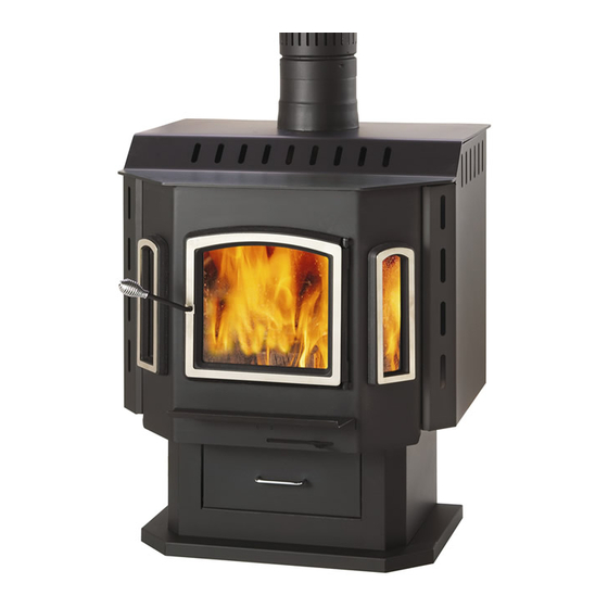
SAHARA WOOD STOVE
Manufactured by : STOVE BUILDER INTERNATIONAL INC.
Tel : (418 ) 878-3040
www.drolet.ca
US ENVIRONMENTAL PROTECTION
AGENCY PHASE II CERTIFIED
WOOD STOVE
Verified and tested following
ULC S627 and UL 1482 Standards
by:
Fax : (418 ) 878-3001
45138A
13-04-2012
Advertisement
Table of Contents

Related Manuals for Drolet SAHARA


Summary of Contents for Drolet SAHARA
- Page 1 OWNER’S MANUAL SAHARA WOOD STOVE US ENVIRONMENTAL PROTECTION AGENCY PHASE II CERTIFIED WOOD STOVE Verified and tested following ULC S627 and UL 1482 Standards Manufactured by : STOVE BUILDER INTERNATIONAL INC. 250, de Copenhague, Saint-Augustin-de-Desmaures (Québec) G3A 2H3 Tel : (418 ) 878-3040 Fax : (418 ) 878-3001 www.drolet.ca...
- Page 2 To receive full warranty coverage, you will need to show evidence of the date you purchased your stove. Keep your sales invoice. We also recommend that you register your warranty online at http://www.drolet.ca/en/service-support/warranty-registration Registering your warranty online will help us track rapidly the information we need on your stove.
-
Page 3: Table Of Contents
2.3 CHIMNEY CONNECTOR ........................ 26 2.4 DRAFT ..............................28 OUTSIDE COMBUSTION AIR ....................28 THE BENEFITS OF INSTALLING A DROLET BLOWER ..........29 SECTION 3.0 OPERATION ..................30 SAFETY INFORMATION ......................30 ... -
Page 4: Tips On Wood Heating
The chimney is the engine that drives the wood-heating system. Use a chimney that is UL-listed, with an inner diameter to match the stove’s outlet collar (6” for all Drolet wood stoves); Try to run the chimney inside the building for as much length as you can. A tall and warm chimney will produce a good draft;... -
Page 5: Section 1.0 - Installation
SECTION 1.0 - INSTALLATION When installed and operated as described in these instructions, the Sahara wood stove is suitable for use as a freestanding wood stove in residential installations. The Sahara wood stove is not intended for installation in a bedroom or a mobile home. -
Page 6: Clearances To Combustibles And Floor Protector
CLEARANCES TO COMBUSTIBLES AND FLOOR PROTECTOR To install your appliance correctly, it is extremely important to respect all clearances to any combustibles as indicated on your stove’s certification label. Clearances to combustible materials (see figure 1.3 to match each letter to a clearance) CLEARANCES (SINGLE WALL PIPE) CANADA 16"... - Page 7 FIGURE 1.3 Clearances to combustible materials and floor protection...
- Page 8 Floor protector If the stove is to be installed on top of a combustible floor, it must be guarded by a non combustible material as shown on figure 1.3 (see the dotted line area). FLOOR PROTECTOR* CANADA 8’’ (205 mm) – Note 1 N/A (Canada only) 8’’...
- Page 9 Reducing Clearances With Shielding TYPE OF PROTECTION Sides and Rear/Back Sheet metal, a minimum of 0,024" (0,61mm) spaced out at least 1" (25mm) by non-combustible spacers (see graphic 2). Ceramic tiles, or an equivalent non-combustible material on fire-proof supports spaced out at least 1" (25 mm) by non- combustible spacers (see graphic 3).
- Page 10 Graphic 1 A- Minimum clearance required between the appliance and an unshielded combustible ceiling. B- 20 in. (500 mm) minimum; C- 1 in. (25 mm) minimum; D- Between 1 in. and 3 in. (25 mm and 75 mm); E- 3 in.(75 mm) minimum; F- 18 in.
- Page 11 Graphic 2 A- 1 in.(25 mm) minimum; 1- Combustible wall; 2- Non-combustible spacers; 3- 0.024’’ (0.61mm) sheet metal. Graphic 3 A- 1 in. (25 mm) minimum; 1- Combustible wall; 2- Non-combustible spacers; 3- Non-combustible support; 4- Ceramic tile or non-combustible material. Graphic 4 A- 1 in.
- Page 12 Graphic 5 A- 1 in. (25 mm) minimum; 1- Combustible wall; 2- Non-combustible spacers; 3- Brick. Graphique 6 A- 1 in. (25 mm) minimum; 1- Combustible wall; 2- Non-combustible spacers; 3- 0.024’’ (0.61 mm) thick sheet metal; 4- Brick.
-
Page 13: Section 2.0 Chimney (Flue System)
SECTION 2.0 CHIMNEY (FLUE SYSTEM) DEFINITIONS For clarity, the following definitions should be used with respect to these instructions: A chimney system consists of a connector off the top of the stove, and a chimne , which attaches to the connector and terminates outside the house. - Page 14 If you are using a masonry chimney, it is important that it be built in compliance with the specifications of the Building Code. It must be lined with fire clay bricks, or clay tiles, sealed together with fire cement, or have a listed solid fuel burning stainless steel liner.
-
Page 15: Step By Step Installation Of Your Factory-Built Chimney
FIGURE 2.2 Minimum Height of the Chimney 2.2.1 Step by step installation of your factory-built chimney The way to install your chimney may vary from one chimney manufacturer to another. The instructions contained in this manual are based on the recommendations of chimney manufacturers whose products are sold at many North American retailers of wood stoves and related heating accessories. - Page 16 FIGURE 2.2.1 (A) Typical installation through the wall 1- Start by positioning your stove where you would like it to go, taking into account the minimum clearances to combustible material. You will then be able to determine where the chimney will pass through the wall.
- Page 17 2- Once the opening completed, you need to frame in the area to allow for the installation of a wall thimble. A wall thimble is not required for installations through concrete walls. 3- You must first secure the wall thimble into the exterior wall surface. Then, do the same inside and fasten the trim plate.
- Page 18 5- You can now install the wall support. Simply slide the wall support up to the tee, ensuring that the adapter on the support engages with the female coupler on the bottom of the tee. When the wall support is level and properly positioned, you can use lag bolts to secure it into the wall studs.
- Page 19 8- Finally, twist on your rain cap and you can head back inside. 9- You are now ready to connect your chimney to your stove. Simply install the inter-connecting stove pipe between the stove pipe adapter and the stove. You can follow the instructions in the following section (section 2.3) of this manual called «...
- Page 20 Typical installation through the ceiling FIGURE 2.2.1 (B) Typical Installation Through the Ceiling 1- Place your stove where you would like it located and use a plumb line to mark the ceiling directly above your stove flue. You will probably have to adjust this position slightly to ensure that your chimney will run between the joists.
- Page 21 2- Before you install the ceiling support, you need to frame the area. 3- To install the ceiling support, just slide the assembly into the framed opening from below. Once you ensure that the finishing plate is flush with the underside of the ceiling and assembly is level, secure it with screws.
- Page 22 6- Now, you can add additional chimney sections. Continue adding chimney lengths until a height of about 2 feet below the next ceiling level. An attic insulation shield must be installed where a chimney passes from a lower living space into an upper living space or attic space. It is designed to keep insulation materials away from the chimney.
-
Page 23: Typical Installation Through An Existing Masonry Chimney
11- You are now ready to connect your chimney to your stove. Simply install the inter-connecting stove pipe between the stove pipe adapter and the stove. You can follow the instructions in the following section (section 2.3) of this manual called « CHIMNEY CONNECTOR». 2.2.2 Typical installation through an existing masonry chimney You can also install your stove using your existing masonry chimney. - Page 24 FIGURE 2.2.2 (B) Factory Built Thimble...
- Page 25 FIGURE 2.2.2 (C) Brick Thimble...
-
Page 26: Chimney Connector
2.3 CHIMNEY CONNECTOR Your chimney connector (commonly called stove pipe) and chimney must have the same diameter as the stove’s exhaust outlet. The stove pipe must be made of aluminized or cold roll steel with a minimum 24- gauge thickness (0.021" or 0.53 mm). It is strictly forbidden to use galvanized steel. The following recommendations may be useful for the installation of your chimney connector: ... - Page 27 FIGURE 2.3 (B) Minimum Slope The assembly should be as short and direct as possible between the stove and chimney (See figure 2.4 (A)). The use of two 45 degree elbows (See figure 2.4 (C)) is often preferable to a single 90 degree elbow (See figure 2.4 (B)) because less turbulence is created in the exhaust flow and they result in less horizontal run.
-
Page 28: Draft
2.4 DRAFT Your E.P.A Drolet stove’s performance will be optimised if it is installed with a chimney (flue) system that provides an adequate draft. The draft is the force that moves air from the appliance up through the chimney and is predominantly affected by the height and diameter of the chimney, as well as the stack temperatures of the stove. -
Page 29: The Benefits Of Installing A Drolet Blower
THE BENEFITS OF INSTALLING A DROLET BLOWER A blower can be installed at the back of your DROLET stove. This option is necessary if you wish to redistribute into a room the heat trapped at the back of your stove. By forcing hot air toward the front, the blower enables you to extend the radiation power of your stove. -
Page 30: Operation
SECTION 3.0 OPERATION Keep these instructions for future reference. WARNING: ANY MODIFICATION OF THE APPLIANCE THAT HAS NOT BEEN APPROVED IN WRITING BY THE TESTING CSA B365 ( ANSI NFPA 211 (USA). AUTHORITY IS CONSIDERED AS BREACHING CANADA DO NOT USE FLAMMABLE LIQUIDS OR AEROSOLS TO START OR REKINDLE THE FIRE ... - Page 31 Even though your Drolet has been specifically designed and tested to prevent smoke spillage, always open the door slowly as this will minimise the likelihood of smoke spillage or a back draft of flame or smoke into the room.
-
Page 32: Fuel
Fuel for the stove must not be stored closer than the required clearances to combustibles (heat sensitive materials). NEVER STORE WOOD IN THE ASH PAN COMPARTMENT. Your Drolet stove is designed to burn . Do not burn coal, charcoal, or trash in the unit. -
Page 33: The Use Of Manufactured Logs
Decorative fireplaces generally have larger, cooler, and less air-tight fireboxes. Your Drolet stove, on the other hand, has a smaller, completely sealed firebox which attains much higher temperatures. It is therefore not designed to support excessive heat caused by the addition of chemicals in manufactured logs. -
Page 34: Maintaining The Fire
15 seconds to avoid smoke spillage before you reload the stove. Your Drolet stove will work best if a thick bed of hot embers is maintained in the bottom of the firebox, and a minimum of two large pieces of seasoned fuel are added. Combustion efficiency is largely related to establishing a hot ember bed, and hot firebox temperatures. -
Page 35: Fan (Blower) Operation
FAN (BLOWER) OPERATION Allow the stove to reach operating temperature (approximately one hour), before turning on the fan. The increased airflow from the fan will cool the firebox and affect the start-up combustion efficiency if the fan is turned on too quick. It is possible to have an automatic activation of the blower with the installation of a thermodisc kit AC05530. -
Page 36: Maintenance
Carefully clean the gasket groove, apply a high temperature silicone sold for this purpose, and install the new gasket. Use only the genuine Drolet gasket. You may light up your stove again approximately 24 hours after having completed this operation. -
Page 37: Ash Removal Using The Ash Drawer
ASH REMOVAL USING THE ASH DRAWER AUTION ASHES CAN START FIRES EVEN AFTER SEVERAL DAYS OF INACTIVITY EVER DISPOSE OF ASHES IN A COMBUSTIBLE CONTAINER EMOVE ASHES WHEN THE STOVE AND ASHES ARE COLD Whenever the ashes get 3 – 4” (76 – 102 mm) deep in the firebox, they should be emptied into the ash drawer, using the following instructions: ... -
Page 38: Chimney (Flue) Cleaning
If creosote has accumulated, it should be removed to reduce the risk of a chimney fire. Call a professional chimney sweep, or go to your local Drolet dealer, purchase a chimney brush, and have the chimney cleaned. -
Page 39: Specifications
SECTION 5.0 SPECIFICATIONS Fuel Type Cordwood Test Standards ULC S627 (CSA B366.2) & UL 1482 residential. Recommended surface : 800 to 2000 sq. ft. Heating capacity* – BTU/hr., EPA test wood: 25,300 BTU/h. Heating capacity* – BTU/hr., seasoned cordwood : 80,000 BTU/h. Optimum efficiency: 78% *Why is the information indicated on the EPA label different than the one advertised? You will notice a difference between the BTU output as indicated on the unit’s white EPA label affixed to the glass and the BTU as... -
Page 40: Drolet Limited Lifetime Warranty
Firebrick *Pictures required Shall your unit or a components be defective, contact immediately your DROLET dealer. Prior to your call make sure you have the following information necessary to your warranty claim treatment: ...