Table of Contents
Advertisement
Quick Links
Advertisement
Table of Contents

Related Manuals for Emerson Energy Meter


Summary of Contents for Emerson Energy Meter
- Page 1 Energy Meter Installation and Operation Manual 026-1726 Rev 2...
- Page 3 Emerson Digital Solutions 1065 Big Shanty Road NW, Suite 100 Kennesaw, GA 30144 USA 770-425-2724 • 1-800-829-2724 www.climate.emerson.com Email: ColdChain.TechnicalServices@Emerson.com...
-
Page 5: Table Of Contents
............................14 DDING AN NERGY ETER 6.3 RS-485 C ............................15 OMMUNICATIONS 6.3.1 Daisy-chaining Devices to the Energy Meter ...................... 15 7 QUICK SETUP INSTRUCTIONS..........................17 8 SOLID-STATE PULSE OUTPUT ..........................18 8.1 S ................................... 18 ULSE 8.2 S – W /P ............................ -
Page 6: Introduction
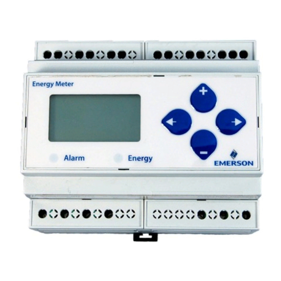
Introduction The Energy Meter (P/N 250-5000) provides a solution for measuring energy data with a single device. Inputs include WARNING! HAZARD OF ELECTRIC Control Power, CT, and 3-phase voltage. The Energy SHOCK, EXPLOSION, OR ARC FLASH Meter supports multiple output options, including solid state relay contacts, Modbus, and pulse. -
Page 7: Specifications
Table 1-1 - Energy Meter Specifications (all models) derate 0.56mA per °C above 25°C) *External DC current limiting is required, Table 1-1 - Energy Meter Specifications see Section 4.2.1, Fuse Recommendations. • Energy Meter Installation and Operation Manual 026-1726 Rev 2... -
Page 8: Notice
Modifications to this product without the express authorization of Emerson nullify this statement. Notice... -
Page 9: Overview
- Energy Meter Dimensions Figure 2-4 - Energy Meter Interface Figure 2-2 - Bottom View (DIN Mount Option) Figure 2-5 - Four Output Options Figure 2-3 - Bottom View (Screw Mount Option) • Energy Meter Installation and Operation Manual 026-1726 Rev 2... -
Page 10: Installation
Exposure to VFD harmonics may cause permanent damage to this device. Types of Mounting The Energy Meter can be mounted in two ways: on standard 35 mm DIN rail or screw-mounted to the interior surface of the enclosure. Figure 3-2 - Screw Mounting 3.1.1... - Page 11 AN-BN Three-Phase Wiring AB, BC, A,B,C 3 A,B,C Delta AB-BC-CA 4 AN-BN-CN Grounded AB, BC, AN, BN, A,B,C 4 A,B,C,N 3L+1n & 5, 6 AB-BC-CA Table 3-1 - System Types • Energy Meter Installation and Operation Manual 026-1726 Rev 2...
-
Page 12: Wiring
Symbol Description Voltage Disconnect Switch Fuse (installer is responsible for ensuring compliance with local requirements. No fuses are included with the Energy Meter.) Earth ground Current Transducer Figure 4-1 - 1-Phase Line-to-Neutral 2- Wire System 1 CT Potential Transformer Protection containing a voltage disconnect switch with a fuse or disconnect circuit breaker. - Page 13 Connection 3 CT Figure 4-6 - 3-Phase 4-Wire Wye Connection 3 CT 3 PT Figure 4-4 - 3-Phase 3-Wire 3 CT no PT WARNING! CTs are referenced to the meter’s neutral (N). • Energy Meter Installation and Operation Manual 026-1726 Rev 2...
-
Page 14: Control Power
Control Power Figure 4-10 - Control Power Transformer (CPT) Connection 4.2.1 Fuse Recommendations Keep the fuses close to the power source (obey local and national code requirements). Figure 4-7 - Direct Connect Control Power (Phase to Phase) For selecting fuses and circuit breakers, use the following criteria: •... -
Page 15: Wiring Connection To Site Supervisor
Wiring Connection to Site Supervisor Figure 4-11 - Site Supervisor Wiring • Energy Meter Installation and Operation Manual 026-1726 Rev 2... -
Page 16: Wiring Connection To E2
Energy Meter. The Energy Meter polarity markings are the inverse of E2; connect the Energy Meter +Data wire to the E2 RS485 - terminal and connect the Energy Meter -Data wire to the E2 RS485 + terminal. The shield cable should be connected to the right most terminal. -
Page 17: Display Screen Diagram
Display Screen Diagram LCD Screen Figure 5-1 - Energy Meter Screen Buttons Figure 5-2 - Energy Meter Buttons • Energy Meter Installation and Operation Manual 026-1726 Rev 2... -
Page 18: Network Setup And Commissioning
E2 PIB COM PORT ASSOCIATIONS Before communicating to an Energy Meter, the port on the E2 Enclosure (Right Side) E2 that has the cable connected to the Energy Meter must be configured to use the Energy Meter. E2 Modem/Expansion COM6... -
Page 19: Adding An Energy Meter
8. In the list of MODBUS devices, choose the select - Network Summary. address number corresponding to the Energy 5. Locate the Energy Meter units you added to the Meter’s dip switch/jumper setting, and press network list (press to scroll through the select it. -
Page 20: Rs-485 Communications
Figure 6-6 List of MODBUS Devices Figure 6-7 Network Summary Screen 9. Repeat Steps 5 and 6 until each Energy Meter device has been commissioned. RS-485 10. When finished, press ) to return to the Network Setup menu, then press... - Page 21 • Wire the RS-485 bus as a daisy chain from device to device, without any stubs. Use a 150 ohm termination resistor at the end of the bus between the Energy Meter’s + and terminals (not included, or use Emerson MODBUS termination block P/N 535-2711).
-
Page 22: Quick Setup Instructions
Quick Setup Instructions 9. - to the S V (Set System Voltage) screen. These instructions assume the meter is set to factory defaults. If it has been previously configured, all to the VLL (or VLN if system is 1L-1n) optional values should be checked. screen and through the digits. -
Page 23: Solid-State Pulse Output
Solid-State Pulse Output The Energy Meter has one normally open (NO) KZ Form A output and one normally closed (NC) KY solid-state output. One is dedicated to energy (Wh), and the other to Alarm. The Energy Meter also provides an additional NO reactive energy (VARh) contact. -
Page 24: Multiflex I/O Board Pulse Limits - Standalone Version Only
MultiFlex I/O Board Pulse Limits - Standalone Version Only The MultiFlex board can read pulses at a maximum of 5HZ or 5PPS. The Energy Meter is capable of pulsing faster than the 5PPS maximum that the MultiFlex board can read. -
Page 25: Ui Menu Abbreviations
Reset System Serial Number RESET RESET Reset Data PASWD PASWD Enter Reset or Setup Password ENERG ENERG Reset Energy Accumulators DEMND DEMND Reset Demand Maximums Table 9-1 - UI Abbreviations • Energy Meter Installation and Operation Manual 026-1726 Rev 2... -
Page 26: User Interface For Data Configuration
User Interface for Data Configuration MultiFlex I/O Board Pulse Limits - Standalone Version Only User Interface for Data Configuration • 21... -
Page 27: Alert/Reset Information
Alert/Reset Information • Energy Meter Installation and Operation Manual 026-1726 Rev 2... -
Page 28: User Interface For Setup
User Interface for Setup MultiFlex I/O Board Pulse Limits - Standalone Version Only User Interface for Setup • 23... - Page 29 • Energy Meter Installation and Operation Manual 026-1726 Rev 2...
-
Page 30: Energy Meter Standard Modbus Default Settings
Log Register Pointer 8 155 (Month/Day) Log Register Pointer 9 156 (Year/Hour) Log Register Pointer 10 157 (Minutes/Seconds) Table 13-1 -MODBUS Default Settings MultiFlex I/O Board Pulse Limits - Standalone Version Only Energy Meter Standard MODBUS Default Settings • 25... -
Page 31: Troubleshooting
Verify that the heart icon is blinking. Check the fuse. meter. Verify the values entered for Energy Meter setup parameters (CT Incorrect setup values and PT ratings, system type, etc.). See the Quick Setup Instructions section. -
Page 32: Appendix Of Compatible Current Transducers
Appendix of Compatible Current Transducers Split Core Current Transducers Part Number Inside Diameter Amperage 251-7010 0.75" 100 AMP 251-7020 1.25" 200 AMP 251-7021 0.75" 200 AMP 251-7030 1.25" 300 AMP 251-7040 2.00" 400 AMP 251-7080 2.00" 800 AMP 251-7120 2.00" 1200 AMP 251-1000 0.75"... - Page 34 Emerson Climate Technologies Retail Solutions, Inc. and/or its affiliates (collectively “Emerson”), reserves the right to modify the designs or specifications of such products at any time without notice. Emerson does not assume responsibility for the selection, use or maintenance of any product. Responsibility for proper selection, use...