Emerson Rosemount 1056 Instruction Manual
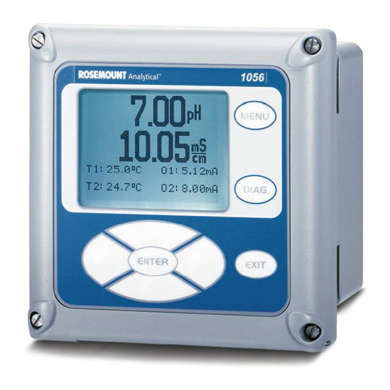
Dual-input intelligent analyzer
Hide thumbs
Also See for Rosemount 1056:
- Quick start manual (36 pages) ,
- Quick start manual (48 pages)

Related Manuals for Emerson Rosemount 1056


Summary of Contents for Emerson Rosemount 1056
- Page 1 Instruction Manual LIQ-MAN-1056 Rev. K April 2017 Rosemount ™ 1056 Dual-Input Intelligent Analyzer...
- Page 2 READ THIS PAGE BEFORE PROCEEDING! RISK OF ELECTRICAL SHOCK Equipment protected throughout by double insulation. Your instrument purchase from Emerson is one of • Installation and servicing of this product may expose personel the finest available for your particular application.
- Page 3 Quick Start Guide Rosemount 1056 Dual-Input Intelligent Analyzer 1. Refer to Section 2.0 for mechanical installation instructions. Wire sensor(s) to the signal boards. See Section 3.0 for wiring instructions. Refer to the sensor instruction sheet for additional details. Make current output, alarm relay and power connections.
- Page 6 About This Document This manual contains instructions for installation and operation of the Rosemount 1056 Dual Input Intelligent Analyzer. The following list provides notes concerning all revisions of this document. Rev. Level Date Notes 01/07 This is the initial release of the product manual. The manual has been reformatted to reflect the Emerson documentation style and updated to reflect any changes in the product offering.
-
Page 7: Table Of Contents
Instruction Manual Table of Contents LIQ-MAN-1056 April 2017 MODEL 1056 DUAL INPUT INTELLIGENT ANALyzER TABLE OF CONTENTS QUICK START GUIDE QUICK REFERENCE GUIDE TABLE OF CONTENTS Section Title Page DESCRIPTION AND SPECIFICATIONS ..............INSTALLATION ....................... Unpacking and Inspection..................Installation........................ WIRING........................General ........................ -
Page 8: Table Of Contents
Instruction Manual Table of Contents LIQ-MAN-1056 April 2017 TABLE OF CONTENTS CONT’D Turbidity ........................6.10 Flow ......................... 6.11 Current Input ......................CALIBRATION ...................... Calibration – Introduction ..................pH Calibration ......................ORP Calibration ....................... Contacting Conductivity Calibration ................. Toroidal Conductivity Calibration ................Chlorine Calibration .................... - Page 9 Instruction Manual Section 1.0: Description and Specification LIQ-MAN-1056 April 2017 Section 1.0 Description and Specifications • MULTI-PARAMETER INSTRUMENT – single or dual input. Choose from pH/ORP/ISE, Resistivity/Conductivity, % Concentration, Chlorine, Oxygen, Ozone, Temperature, Turbidity, Flow, and 4-20mA Current Input. • LARGE DISPLAY – large easy-to-read process measurements. •...
- Page 10 Instruction Manual Section 1.0: Description and Specification LIQ-MAN-1056 April 2017 Diagnostics: The analyzer continuously monitors Special Measurements: The Model 1056 offers itself and the sensor(s) for problematic conditions. measuring capabilities for many applications. The display flashes Fault and/or Warning when these Single or Dual Turbidity: Ideal in municipal appli- conditions occur.
- Page 11 Instruction Manual Section 1.0: Description and Specification LIQ-MAN-1056 April 2017 1.2 Specifications - General Power: Code -01: 115/230 VAC ±15%, 50/60 Hz. 10W. Code -02: 20 to 30 VDC. 15 W. Enclosure: Polycarbonate. Type 4X, IP65. Code -03: 85 to 265 VAC, 47.5 to 65.0 Hz, Note: To ensure a water-tight seal, tighten all four front panel switching.
- Page 12 Instruction Manual Section 1.0: Description and Specification LIQ-MAN-1056 April 2017 1.3 Contacting Conductivity (Code -20 and -30) Measures conductivity in the range 0 to 600,000 S/cm Temperature Specifications: (600mS/cm). Measurement choices are conductivity, resistivity, total dissolved solids, salinity, and % concen- Temperature range 0-150ºC tration.
- Page 13 Instruction Manual Section 1.0: Description and Specification LIQ-MAN-1056 April 2017 1.4 Toroidal Conductivity (Code -21 and -31) Measures conductivity in the range of 1 (one) S/cm to Temperature Specifications: 2,000,000 S/cm (2 S/cm), Measurement choices are conductivity, resistivity, total dissolved solids, salinity, Temperature range -25 to 210ºC (-13 to 410ºF) and % concentration.
- Page 14 Instruction Manual Section 1.0: Description and Specification LIQ-MAN-1056 April 2017 1.5 pH/ORP/ISE (Code -22 and -32) Performance Specifications (ORP Input) For use with any standard pH or ORP sensor. Measurement choices are pH, ORP, Redox, ammonia, Measurement Range [ORP] -1500 to +1500 mV fluoride or custom ISE.
- Page 15 Instruction Manual Section 1.0: Description and Specification LIQ-MAN-1056 April 2017 1.6 Flow (Code -23 and -33) For use with most pulse signal flow sensors, the 1056 Totalized Flow: 0 – 9,999,999,999,999 Gallons or m3, user-selectable units of measurement include flow rates 0 –...
- Page 16 Instruction Manual Section 1.0: Description and Specification LIQ-MAN-1056 April 2017 1.8 Chlorine (Code -24 and -34) Free and Total Chlorine Recommended Sensors The 1056 is compatible with the 499ACL-01 free chlorine Rosemount Model 499ACL-03 Monochloramine sensor sensor and the 499ACL-02 total chlorine sensor. The pH-Independent Free Chlorine 499ACL-02 sensor must be used with the TCL total chlorine sample conditioning system.
- Page 17 Instruction Manual Section 1.0: Description and Specification LIQ-MAN-1056 April 2017 Dissolved Oxygen (Code -25 1.10 Dissolved Ozone (Code -26 and -35) and -36) The 1056 is compatible with the 499ADO, 499ATrDO, The 1056 is compatible with the Model 499AOZ sen- Hx438, and Gx438 dissolved oxygen sensors and the sor.
- Page 18 Instruction Manual Section 1.0: Description and Specification LIQ-MAN-1056 April 2017 1.11 Turbidity (Code 27 and 37) Performance Specifications The 1056 instrument is available in single and dual tur- bidity configurations for the Clarity II turbidimeter. It is Units: Turbidity (NTU, FTU, or FNU); total suspended ®...
-
Page 19: Installation
Inspect the shipping container. If it is damaged, contact the shipper immediately for instructions. Save the box. If there is no apparent damage, unpack the container. Be sure all items shown on the packing list are present. If items are missing, notify Emerson immediately. 2.2 Installation 2.2.1 General Information... - Page 20 Figure 2-1 Panel Mounting Dimensions MILLIMETER INCH 126.4 17.13 101.6 4.00 154.9 154.9 Front View Side View 126.4 76.2 41.4 Bottom View 152.73 Note: Panel mounting seal integrity (4/4X) for outdoor applications is the responsibility of the end user.
- Page 21 Figure 2-2 Pipe and Wall Mounting Dimensions (Mounting bracket PN:23820-00) MILLIMETER INCH Wall / Surface Mount 154.9 33.5 154.9 Side View Front View Pipe Mount Bottom View 33.5 80.01 45.21 108.9 Side View 71.37 The front panel is hinged at the bottom. The panel swings down for easy access to the wiring locations.
- Page 22 Instruction Manual Section 2.0: Installation LIQ-MAN-1056 April 2017 FIGURE 2-3. CSA Non Incendive Field Wiring Installation ASSY 24236- ASSY 24355- ASSY 24312- ASSY 24203- R75 R73...
- Page 23 Instruction Manual Section 2.0: Installation LIQ-MAN-1056 April 2017 FIGURE 2-3. FM Non Incendive Field Wiring Installation...
- Page 24 Instruction Manual Section 2.0: Installation LIQ-MAN-1056 April 2017 FIGURE 2-3. CSA NonIncendive Class I, Division 2 Certified product for selected configurations...
- Page 25 Instruction Manual Section 2.0: Installation LIQ-MAN-1056 April 2017 FIGURE 2-3. CSA NonIncendive Class I, Division 2 Certified product for selected configurations...
- Page 26 Instruction Manual Section 2.0: Installation LIQ-MAN-1056 April 2017 FIGURE 2-3. FM NonIncendive Class I, Division 2 Certified product for selected configurations...
- Page 27 Instruction Manual Section 2.0: Installation LIQ-MAN-1056 April 2017 FIGURE 2-3. FM NonIncendive Class I, Division 2 Certified product for selected configurations...
- Page 28 Instruction Manual Section 2.0: Installation LIQ-MAN-1056 April 2017...
-
Page 29: Wiring
Instruction Manual Section 3.0: Wiring LIQ-MAN-1056 April 2017 Section 3.0 Wiring 3.1 General 3.2 Preparing Conduit Openings 3.3 Preparing Sensor Cable 3.4 Power, Output, and Sensor Connections 3.1 General The 1056 is easy to wire. It includes removable connectors and slide-out signal input boards. The front panel is hinged at the bottom. -
Page 30: Preparing Sensor Cable
Instruction Manual Section 3.0: Wiring LIQ-MAN-1056 April 2017 3.3 Preparing Sensor Cable The 1056 is intended for use with all Rosemount sensors. Refer to the sensor installation instructions for details on preparing sensor cables. 3.4 Power, Output, and Sensor Connections 3.4.1 Power Wiring Three Power Supplies are offered for Model 1056: a. - Page 31 Instruction Manual Section 3.0: Wiring LIQ-MAN-1056 April 2017 3.4.2 Current Output Wiring All instruments are shipped with two 4-20 mA current outputs. Wiring locations for the outputs are on the Main board which is mounted on the hinged door of the instrument.
- Page 32 Instruction Manual Section 3.0: Wiring LIQ-MAN-1056 April 2017 Sec. 3.4 Signal board wiring Figure 3-6 Contacting Conductivity signal board and Sensor cable leads Figure 3-7 Toroidal Conductivity Signal board and Sensor cable leads...
- Page 33 Instruction Manual Section 3.0: Wiring LIQ-MAN-1056 April 2017 Figure 3-8 pH/ORP/ISE signal board and Sensor cable leads Figure 3-9 Amperometric signal (Chlorine, Oxygen, Ozone) board and Sensor cable leads...
- Page 34 Instruction Manual Section 3.0: Wiring LIQ-MAN-1056 April 2017 Figure 3-10 Turbidity signal board with plug-in Sensor connection Figure 3-11 Flow/Current Input signal board and Sensor cable leads...
- Page 35 Instruction Manual Section 3.0: Wiring LIQ-MAN-1056 April 2017 FIGURE 3-12 Power Wiring for the 1056 115/230VAC Power Supply (-01 Order Code) FIGURE 3-13 Power Wiring for the 1056 85-265 VAC Power Supply (-03 ordering code)
- Page 36 Instruction Manual Section 3.0: Wiring LIQ-MAN-1056 April 2017 FIGURE 3-14 Output Wiring for Model 1056 Main PCB FIGURE 3-15 Power Wiring for Model 1056 24VDC Power Supply (-02 ordering code)
-
Page 37: Display And Operation
Instruction Manual Section 4.0: Display and Operation LIQ-MAN-1056 April 2017 Section 4.0 Display and Operation 4.1 User Interface 4.2 Keypad 4.3 Main Display 4.4 Menu System 4.1 User Interface The 1056 has a large display which shows two live measurement readouts in large digits and up to four additional process variables or diagnostic parameters concurrently. -
Page 38: Main Display
Instruction Manual Section 4.0: Display and Operation LIQ-MAN-1056 April 2017 Pressing the DIAG key displays active Faults and Cable Resistance, Temperature Sensor Resistance, Warnings, and provides detailed instrument information Signal Board software version. and sensor diagnostics including: Faults, Warnings, The ENTER key. Pressing ENTER stores numbers and Sensor 1 and 2 information, Out 1 and Out 2 live current values, Instrument Software version, and AC frequen- settings and moves the display to the next screen. -
Page 39: Menu System
Instruction Manual Section 4.0: Display and Operation LIQ-MAN-1056 April 2017 Fault and Warning banner: If the analyzer detects a problem with itself or the sensor the word Fault or Warning will appear at the bottom of the display. A fault requires immediate attention. A warning indicates a problematic condition or an impending fail- ure. - Page 40 Instruction Manual Section 5.0: Programming the Analyzer - Basics LIQ-MAN-1056 April 2017 FIGURE 4-1 Formatting the Main Display...
-
Page 41: General
Instruction Manual Section 5.0: Programming the Analyzer - Basics LIQ-MAN-1056 April 2017 Section 5.0 Programming The Analyzer - Basics General Changing Start-Up Settings Programming Temperature Configuring and Ranging 4-20ma Outputs Setting Security Codes Security Access Using Hold Resetting Factory Defaults – Reset Analyzer Programming Alarm Relays 5.1 General Section 5.0 describes the following programming functions:... -
Page 42: Choosing Temperature Units And Automatic/Manual Temperature Compensation
Instruction Manual Section 5.0: Programming the Analyzer - Basics LIQ-MAN-1056 April 2017 5.3 Choosing Temperature Units And Automatic/Manual Temperature Compensation 5.3.1 Purpose Most liquid analytical measurements (except ORP) require temperature compensation. The Model 1056 performs temperature compensation automatically by S1: 1.234µS/cm 25.0ºC applying internal temperature correction algorithms. - Page 43 Instruction Manual Section 5.0: Programming the Analyzer - Basics LIQ-MAN-1056 April 2017 5.4.3 Procedure: Configure Outputs S1: 1.234µS/cm 25.0ºC Under the Program/Outputs menu, the adjacent screen S2: 12.34pH 25.0ºC will appear to allow configuration of the outputs. Follow OutputM Configure the menu screens in Fig.
-
Page 44: Setting A Security Code
Instruction Manual Section 5.0: Programming the Analyzer - Basics LIQ-MAN-1056 April 2017 5.5 Setting A Security Code Scroll down to Security. Select Security. The security entry screen appears. Enter a three digit security code for each of the desired 5.5.1 Purpose security levels. -
Page 45: Security Access
Instruction Manual Section 5.0: Programming the Analyzer - Basics LIQ-MAN-1056 April 2017 5.6 Security Access 5.7 Using Hold 5.6.1 How the Security Code Works 5.7.1 Purpose When entering the correct access code for the The analyzer output is always proportional to measured Calibration/Hold security level, the Calibration and value. - Page 46 Instruction Manual Section 5.0: Programming the Analyzer - Basics LIQ-MAN-1056 April 2017 5.8 Resetting Factory Default Settings 5.8.1 Purpose This section describes how to restore factory calibration and default values. The process also clears all fault messages and returns the display to the first Quick Start screen. The Model 1056 offers three options for resetting factory defaults.
-
Page 47: Alarm Relays
Instruction Manual Section 5.0: Programming the Analyzer - Basics LIQ-MAN-1056 April 2017 5.9 Programming Alarm Relays 5.9.1 Purpose The Model 1056 24VDC (02 order code) and the AC switching power supply (03 order code) provide four alarm relays for process measurement or temperature. Each alarm can be configured as a fault alarm instead of a process alarm. - Page 48 Instruction Manual Section 5.0: Programming the Analyzer - Basics LIQ-MAN-1056 April 2017 5.9.2 Procedure – Enter Setpoints S1: 1.234µS/cm 25.0ºC Under the Program/Alarms menu, this screen will S2: 12.34pH 25.0ºC Alarm1 S2 Setpoint appear to allow configuration of the alarm relays. +100.0uS/cm Enter the desired value for the process measurement or temperature at which to activate an alarm event.
- Page 49 Instruction Manual Section 5.0: Programming the Analyzer - Basics LIQ-MAN-1056 April 2017 5.9.8 Procedure – Interval time S1: 1.234µS/cm 25.0ºC Under the Alarms Settings menu, this screen will S2: 12.34pH 25.0ºC Alarm1 Interval Time appear to set the interval time. Enter the fixed time in 024.0 hrs hours between relay activations.
- Page 50 Instruction Manual Section 6.0: Programming the Measurements LIQ-MAN-1056 April 2017...
-
Page 51: Programming - Measurements
Instruction Manual Section 6.0: Programming the Measurements LIQ-MAN-1056 April 2017 Section 6.0 Programming - Measurements 6.1 Configuring Measurements – Introduction 6.2 pH 6.3 ORP 6.4 Contacting Conductivity 6.5 Toroidal Conductivity 6.6 Chlorine 6.6.1 Free Chlorine 6.6.2 Total Chlorine 6.6.3 Monochloramine 6.6.4 pH-Independent Free Chlorine 6.7 Oxygen... - Page 52 Instruction Manual Section 6.0: Programming the Measurements LIQ-MAN-1056 April 2017 6.2 pH Measurement Programming 6.2.1 Description This section describes how to configure the Model 1056 analyzer for pH measurements. The following programming and configuration functions are covered. TABLE 6-1. pH Measurement Programming Measure Sec.
- Page 53 Instruction Manual Section 6.0: Programming the Measurements LIQ-MAN-1056 April 2017 6.2.4 Solution Temperature Correction S1: 1.234µS/cm 25.0ºC The display screen for selecting the Solution S2: 12.34pH 25.0ºC temperature correction algorithm is shown. The default SN Sol’n Temp Corr. value is displayed in bold type. Refer to the pH/ORP Programming flow diagram to complete this function.
- Page 54 Instruction Manual Section 6.0: Programming the Measurements LIQ-MAN-1056 April 2017 A detailed flow diagram for ORP programming is provided at the end of Sec. 6 to guide you through all basic programming and configuration functions. S1: 1.234µS/cm 25.0ºC To configure the ORP measurement board: S2: 12.34pH 25.0ºC SN Configure...
-
Page 55: Contacting Conductivity
Instruction Manual Section 6.0: Programming the Measurements LIQ-MAN-1056 April 2017 6.4 Contacting Conductivity Measurement Programming 6.4.1 Description The section describes how to configure the Model 1056 analyzer for conductivity measurements using contacting conductivity sensors. The following programming and configuration functions are covered. TABLE 6-3. - Page 56 Instruction Manual Section 6.0: Programming the Measurements LIQ-MAN-1056 April 2017 6.4.3 Measure S1: 1.234µS/cm 25.0ºC The display screen for selecting the measurement is S2: 12.34pH 25.0ºC SN Measurement shown. The default value is displayed in bold type. Conductivity Refer to the contacting conductivity Programming flow Resistivity diagram to complete this function.
- Page 57 Instruction Manual Section 6.0: Programming the Measurements LIQ-MAN-1056 April 2017 6.4.9 Slope The display screen for Entering the conductivity/temp S1: 1.234µS/cm 25.0ºC Slope is shown. The default value is displayed in bold S2: 12.34pH 25.0ºC SN Slope type. Refer to the contacting conductivity Programming 2.00 %/ºC flow diagram to complete this function.
-
Page 58: Toroidal Conductivity
Instruction Manual Section 6.0: Programming the Measurements LIQ-MAN-1056 April 2017 6.5 Toroidal Conductivity Measurement Programming 6.5.1 Description The section describes how to configure the Model 1056 analyzer for conductivity measurements using inductive/toroidal sensors. The following programming and configuration functions are covered. TABLE 6-4. - Page 59 Instruction Manual Section 6.0: Programming the Measurements LIQ-MAN-1056 April 2017 6.5.3 Measure S1: 1.234µS/cm 25.0ºC The display screen for selecting the measurement is S2: 12.34pH 25.0ºC shown. The default value is displayed in bold type. SN Measurement Conductivity Refer to the toroidal conductivity Programming flow diagram Resistivity to complete this function.
- Page 60 Instruction Manual Section 6.0: Programming the Measurements LIQ-MAN-1056 April 2017 6.5.7 Slope S1: 1.234µS/cm 25.0ºC The display screen for Entering the conductivity/temp S2: 12.34pH 25.0ºC Slope is shown. The default value is displayed in bold SN Slope type. Refer to the toroidal conductivity Programming 2.00%/ºC flow diagram to complete this function.
-
Page 61: Chlorine
Instruction Manual Section 6.0: Programming the Measurements LIQ-MAN-1056 April 2017 6.6 Chlorine Measurement Programming With a Chlorine measurement board installed, Model 1056 can measure any of four variants of Chlorine: • Free Chlorine • Total Chlorine • Monochloramine • pH-independent Free Chlorine The section describes how to configure the Model 1056 analyzer for Chlorine measurements. - Page 62 Instruction Manual Section 6.0: Programming the Measurements LIQ-MAN-1056 April 2017 The following sub-sections provide you with the initial display screen that appears for each configuration function. Use the flow diagram for chlorine programming at the end of Sec. 6 and the Model 1056 live screen prompts for each function to complete configuration and programming.
-
Page 63: Total Chlorine
Instruction Manual Section 6.0: Programming the Measurements LIQ-MAN-1056 April 2017 6.6.2 Total Chlorine Measurement Programming 6.6.2.1 Description This Chlorine sub-section describes how to configure the Model 1056 analyzer for Total Chlorine measurement using amperometric chlorine sensors. The following programming and configuration functions are covered: TABLE 6-6. -
Page 64: Monochloramine
Instruction Manual Section 6.0: Programming the Measurements LIQ-MAN-1056 April 2017 6.6.2.4 Filter S1: 1.234µS/cm 25.0ºC The display screen for entering the input filter value in S2: 12.34pH 25.0ºC seconds is shown. The default value is displayed in SN Input filter bold type. -
Page 65: Ph-Independent Free Chlorine
Instruction Manual Section 6.0: Programming the Measurements LIQ-MAN-1056 April 2017 6.6.3.3 Units S1: 1.234µS/cm 25.0ºC The display screen for selecting units as ppm or mg/L is S2: 12.34pH 25.0ºC shown. The default value is displayed in bold type. SN Units Refer to the Chlorine Programming flow diagram to complete this function. - Page 66 Instruction Manual Section 6.0: Programming the Measurements LIQ-MAN-1056 April 2017 The following sub-sections provide you with the initial display screen that appears for each configuration function. Use the flow diagram for chlorine programming at the end of Sec. 6 and the Model 1056 live screen prompts for each function to complete configuration and programming.
-
Page 67: Oxygen
Instruction Manual Section 6.0: Programming the Measurements LIQ-MAN-1056 April 2017 6.7 Oxygen Measurement Programming 6.7.1 Description This section describes how to configure the Model 1056 analyzer for dissolved and gaseous oxygen measurement using amperometric oxygen sensors. The following programming and configuration functions are covered: TABLE 6-9. - Page 68 Instruction Manual Section 6.0: Programming the Measurements LIQ-MAN-1056 April 2017 6.7.4 Partial Press S1: 1.234µS/cm 25.0ºC The display screen for selecting pressure units for S2: 12.34pH 25.0ºC Partial pressure is shown. This selection is needed if SN Partial Press mm Hg the specified measurement is Partial pressure.
-
Page 69: Ozone
Instruction Manual Section 6.0: Programming the Measurements LIQ-MAN-1056 April 2017 6.8 Ozone Measurement Programming 6.8.1 Description This section describes how to configure the 1056 analyzer for ozone measurement using amperometric ozone sen- sors. The following programming and configuration functions are covered: TABLE 6-10. -
Page 70: Turbidity
Instruction Manual Section 6.0: Programming the Measurements LIQ-MAN-1056 April 2017 6.9 Turbidity Measurement Programming 6.9.1 Description This section describes how to configure the Model 1056 analyzer for Turbidity measurements. The following programming and configuration functions are covered. TABLE 6-11 Turbidity Measurement Programming Measure Sec. - Page 71 Instruction Manual Section 6.0: Programming the Measurements LIQ-MAN-1056 April 2017 If TSS data (Total Suspended Solids) calculation is selected, the following screen will be displayed. Refer S1: 1.234µS/cm 25.0ºC to the Turbidity programming flow diagram to complete S2: 12.34pH 25.0ºC SN Units this function.
- Page 72 Instruction Manual Section 6.0: Programming the Measurements LIQ-MAN-1056 April 2017 When the TSS data entry is complete, press ENTER. The display will confirm the determination of a TSS S1: 1.234µS/cm 25.0ºC straight line curve fit to the entered NTU/turbidity data S2: 12.34pH 25.0ºC SN TSS Data...
-
Page 73: Flow
Instruction Manual Section 6.0: Programming the Measurements LIQ-MAN-1056 April 2017 6.10 Flow Measurement Programming 6.10.1 Description This section describes how to configure the 1056 analyzer for flow measurement when used with a compatible pulse flow sensor. The following programming and configuration functions are covered. TABLE 6-12 Flow Measurement Programming Measure Sec. -
Page 74: Current Input
Instruction Manual Section 6.0: Programming the Measurements LIQ-MAN-1056 April 2017 6.11 Current Input Programming 6.11.1 Description This section describes how to configure the Model 1056 analyzer for current input measurement when wired to an external device that transmits 4-20mA or 0-20mA analog current output. The following programming and configu- ration functions are covered. - Page 75 Instruction Manual Section 6.0: Programming the Measurements LIQ-MAN-1056 April 2017 6.11.4 Units S1: 1.234µS/cm 25.0ºC The display screen for selecting measurement units is S2: 12.34pH 25.0ºC SN Units shown. The default value for temperature is displayed in °C bold type. Refer to the current input Programming flow ºF diagram to complete this function.
- Page 76 Instruction Manual Section 6.0: Programming the Measurements LIQ-MAN-1056 April 2017 6.11.6 Low Value S1: 1.234µS/cm 25.0ºC The display screen for entering the Low Value to be S2: 12.34pH 25.0ºC assigned to 4mA (or 0mA) current input is shown. The SN Low Value default value for temperature is displayed in bold type.
-
Page 77: Liq-Man-1056 April
Instruction Manual Section 6.0: Programming the Measurements LIQ-MAN-1056 April 2017... - Page 78 Instruction Manual Section 6.0: Programming the Measurements LIQ-MAN-1056 April 2017...
- Page 79 Instruction Manual Section 6.0: Programming the Measurements LIQ-MAN-1056 April 2017...
- Page 80 Instruction Manual Section 6.0: Programming the Measurements LIQ-MAN-1056 April 2017...
- Page 81 Instruction Manual Section 6.0: Programming the Measurements LIQ-MAN-1056 April 2017 FIGURE 6-4 Configure Chlorine Measurements FIGURE 6-6 Configure Ozone Measurements...
- Page 82 Instruction Manual Section 6.0: Programming the Measurements LIQ-MAN-1056 April 2017...
- Page 83 Instruction Manual Section 6.0: Programming the Measurements LIQ-MAN-1056 April 2017 FIGURE 6-8 Configure Flow Measurement FIGURE 6-9 Configure mA Current Input Measurement...
- Page 84 Instruction Manual Section 6.0: Programming the Measurements LIQ-MAN-1056 April 2017...
-
Page 85: Calibration
Instruction Manual Section 7.0: Calibration LIQ-MAN-1056 April 2017 Section 7.0 Calibration 7.1 Calibration – Introduction 7.2 Ph Calibration 7.3 Orp Calibration 7.4 Contacting Conductivity Calibration 7.5 Toroidal Conductivity Calibration 7.6 Chlorine Calibration 7.6.1 Free Chlorine 7.6.2 Total Chlorine 7.6.3 Monochloramine 7.6.4 pH-Independent Free Chlorine 7.7 Oxygen Calibration... -
Page 86: Ph Calibration
Instruction Manual Section 7.0: Calibration LIQ-MAN-1056 April 2017 7.2 pH Calibration 7.2.1 Description New sensors must be calibrated before use. Regular recalibration is also necessary. Use auto calibration instead of manual calibration. Auto calibration avoids common pitfalls and reduces errors. The analyzer recognizes the buffers and uses temperature-corrected pH values in the calibration. - Page 87 Instruction Manual Section 7.0: Calibration LIQ-MAN-1056 April 2017 The following screen will appear if the auto cal is S1: 1.234µS/cm 25.0ºC successful. The screen will return to the pH Buffer Cal S2: 12.34pH 25.0ºC Menu. SN pH Auto Cal Slope: 59.16 mV/pH Offset: 60 mV The following screens may appear if the auto cal is unsuccessful.
-
Page 88: Orp Calibration
Instruction Manual Section 7.0: Calibration LIQ-MAN-1056 April 2017 The following screen may appear if ORP Cal is unsuccessful. S1: 1.234µS/cm 25.0ºC An Offset Error will generate this screen display: S2: 12.34pH 25.0ºC SN Standardize Offset Error If the ORP Cal is successful, the screen will return to the Calculated: 96mV Cal sub-menu. -
Page 89: Contacting Conductivity Calibration
Instruction Manual Section 7.0: Calibration LIQ-MAN-1056 April 2017 7.4 Contacting Conductivity Calibration standard solution. Use this method if the sensor can be easily removed from the process piping and a standard is available. Be careful using standard solutions having 7.4.1 Description conductivity less than 100 µS/cm. - Page 90 Instruction Manual Section 7.0: Calibration LIQ-MAN-1056 April 2017 7.4.2 Entering The Cell Constant New conductivity sensors rarely need calibration. The cell constant printed on the label is sufficiently accurate for most applications. The cell constant should be entered: • When the unit is installed for the first time S1: 1.234µS/cm 25.0ºC •...
- Page 91 Instruction Manual Section 7.0: Calibration LIQ-MAN-1056 April 2017 The adjacent screen will appear if In Process Cal is suc- S1: 1.234µS/cm 25.0ºC cessful. The screen will return to the conductivity Cal S2: 12.34pH 25.0ºC SN InProcess Cal Menu. Updated cell constant: 1.00135/cm The adjacent screen may appear if In Process Cal is...
-
Page 92: Toroidal Conductivity Calibration
Instruction Manual Section 7.0: Calibration LIQ-MAN-1056 April 2017 7.5 Toroidal Conductivity Calibration 7.5.1 Description Calibration is the process of adjusting or standardizing the analyzer to a lab test or a calibrated laboratory instru- ment, or standardizing to some known reference (such as a conductivity standard). This section contains procedures for the first time use and for routine calibration of the Model 1056 analyzer. - Page 93 Instruction Manual Section 7.0: Calibration LIQ-MAN-1056 April 2017 7.5.2 Entering The Cell Constant New conductivity sensors rarely need calibration. The cell constant printed on the label is sufficiently accurate for most applications. The cell constant should be entered: • When the unit is installed for the first time •...
-
Page 94: Free Chlorine
Instruction Manual Section 7.0: Calibration LIQ-MAN-1056 April 2017 The following screen will appear if In Process Cal is S1: 1.234µS/cm 25.0ºC successful. The screen will return to the conductivity S2: 12.34pH 25.0ºC Cal Menu. SN InProcess Cal Updated cell constant: 3.01350/cm This screen may appear if In Process Cal is unsuccessful. -
Page 95: Chlorine Calibration
Instruction Manual Section 7.0: Calibration LIQ-MAN-1056 April 2017 TABLE 7-5 Free Chlorine Calibration Routines Description Measure Sec. Calibration function: default value Free Chlorine 7.6.1.2 Zero Cal Zeroing the sensor in solution with zero free chlorine 7.6.1.3 Standardizing to a sample of known chlorine concentration In Process Cal A detailed flow diagram is provided at the end of Sec. - Page 96 Instruction Manual Section 7.0: Calibration LIQ-MAN-1056 April 2017 If the In Process Cal is successful, the screen will return S1: 1.234µS/cm 25.0ºC to the Cal sub-menu. S2: 12.34pH 25.0ºC The adjacent screen may appear if In Zero Cal is unsuc- SN InProcess Cal cessful.
- Page 97 Instruction Manual Section 7.0: Calibration LIQ-MAN-1056 April 2017 The following sub-sections provide you with the initial S1: 1.234µS/cm 25.0ºC display screen that appears for each calibration routine. S2: 12.34pH 25.0ºC Use the flow diagram for Chlorine calibration at the SN Calibration end of Sec.
- Page 98 Instruction Manual Section 7.0: Calibration LIQ-MAN-1056 April 2017 7.6.3 Calibration - Monochloramine The purpose of the In Process calibration is to establish 7.6.3.1 Description the slope of the calibration curve. Because stable A monochloramine sensor generates a current directly monochloramine standards do not exist, the sensor proportional to the concentration of monochloramine in must be calibrated against a test run on a grab sample the sample.
- Page 99 Instruction Manual Section 7.0: Calibration LIQ-MAN-1056 April 2017 7.6.3.2 zeroing The Sensor S1: 1.234µS/cm 25.0ºC The adjacent screen will appear during Zero Cal. Be S2: 12.34pH 25.0ºC sure sensor has been running in zero solution for at SN Zero Cal Zeroing least two hours before starting zero step.
- Page 100 Instruction Manual Section 7.0: Calibration LIQ-MAN-1056 April 2017 7.6.4 pH-Independent Free Chlorine The purpose of the In Process calibration is to Measurement establish the slope of the calibration curve. Because stable chlorine standards do not exist, the sensor must be calibrated against a test run on a grab sample of 7.6.4.1 Description the process liquid.
- Page 101 Instruction Manual Section 7.0: Calibration LIQ-MAN-1056 April 2017 The following sub-sections provide you with the initial display screen that appears for each calibration Use the flow diagram for Chlorine routine. S1: 1.234µS/cm 25.0ºC calibration at the end of Sec. 7 and the live screen S2: 12.34pH 25.0ºC SN Calibration...
- Page 102 Instruction Manual Section 7.0: Calibration LIQ-MAN-1056 April 2017 7.7 Calibration — Oxygen diffusion rate depends on the difference in chemical potential between oxygen in the sensor and oxygen in the sample. An electrochemical reaction, which 7.7.1 Description destroys any oxygen molecules entering the sensor, Oxygen sensors generate a current directly proportional keeps the concentration (and the chemical potential) of to the concentration of dissolved oxygen in the sample.
-
Page 103: Oxygen Calibration
Instruction Manual Section 7.0: Calibration LIQ-MAN-1056 April 2017 TABLE 7- 9 Oxygen Calibration Routines Measure Sec. Calibration function: default value Description Oxygen 7.7.2 Zero Cal Zeroing the sensor in a medium with zero oxygen 7.7.3 Calibrating the sensor in a water-saturated air sample Air Cal 7.7.4 In Process Cal... - Page 104 Instruction Manual Section 7.0: Calibration LIQ-MAN-1056 April 2017 7.7.2 zeroing The Sensor 1.234 nA The adjacent screen will appear during Zero Cal 1.456 nA SN Zero Cal Zeroing Wait The adjacent screen will appear if In Zero Cal is suc- 1.234 nA cessful.
-
Page 105: Ozone Calibration
Instruction Manual Section 7.0: Calibration LIQ-MAN-1056 April 2017 7.8 Calibration — Ozone against a test run on a grab sample of the process liquid. Several manufacturers offer portable test kits for this purpose. Observe the following precautions when taking 7.8.1 Description and testing the grab sample. - Page 106 Instruction Manual Section 7.0: Calibration LIQ-MAN-1056 April 2017 The following sub-sections provide you with the S1: 1.234µS/cm 25.0ºC initial display screen that appears for each calibration S2: 12.34pH 25.0ºC routine. Use the flow diagram for Ozone calibration SN Calibration at the end of Sec. 7 and the live screen prompts to Zero Cal complete calibration.
-
Page 107: Temperature Calibration
Instruction Manual Section 7.0: Calibration LIQ-MAN-1056 April 2017 7.9 Calibrating Temperature 7.9.1 Description Most liquid analytical measurements require temperature compensation (except ORP). The Model 1056 performs temperature compensation automatically by applying internal temperature correction algorithms. Temperature cor- rection can also be turned off. If temperature correction is off, the Model 1056 uses the manual temperature entered by the user in all temperature correction calculations. - Page 108 Instruction Manual Section 7.0: Calibration LIQ-MAN-1056 April 2017 7.10 Turbidity 7.10.1 Description This section describes how to calibrate the turbidity sensor against a user-prepared standard as a 2-point calibra- tion with di-ionized water, against a 20 NTU user-prepared standard as a single point calibration, and against a grab sample using a reference turbidimeter.
- Page 109 Instruction Manual Section 7.0: Calibration LIQ-MAN-1056 April 2017 This screen appears after selecting Slope calibration. S1: 1.234µS/cm 25.0ºC S2: 12.34pH 25.0ºC SN Slope Cal Sensor in pure H2O? Press ENTER The following screen will appear if Slope Cal is suc- S1: 1.234µS/cm 25.0ºC cessful.
-
Page 110: Pulse Flow
Instruction Manual Section 7.0: Calibration LIQ-MAN-1056 April 2017 7.10.4 Grab Calibration - Turbidity This screen appears after selecting Grab calibration. If desired, the turbidity sensor can be calibrated S1: 1.234µS/cm 25.0ºC against the turbidity reading from another instrument. S2: 12.34pH 25.0ºC The analyzer treats the value entered by the user as SN Grab Cal... - Page 111 Instruction Manual Section 7.0: Calibration LIQ-MAN-1056 April 2017 To calibrate Pulse Flow scroll to the desired item and S1: 1.234µS/cm 25.0ºC press ENTER. S2: 12.34pH 25.0ºC SN Calibration K Factor: 12.34 p/Gal The following sub-sections provide you with the initial Freq/Velocity &...
- Page 112 Instruction Manual Section 7.0: Calibration LIQ-MAN-1056 April 2017 The following screen may appear if the entries are S1: 1.234µS/cm 25.0ºC unsuccessful. S2: 12.34pH 25.0ºC SN Freq/Velocity&Pipe Calibration Error Press EXIT 7.11.4 Calibration — In Process Cal S1: 1.234µS/cm 25.0ºC This screen appears after selecting In Process Cal. S2: 12.34pH 25.0ºC SN InProcess Cal...
- Page 113 Instruction Manual Section 7.0: Calibration LIQ-MAN-1056 April 2017...
- Page 114 Instruction Manual Section 7.0: Calibration LIQ-MAN-1056 April 2017...
- Page 115 Instruction Manual Section 7.0: Calibration LIQ-MAN-1056 April 2017...
- Page 116 Instruction Manual Section 7.0: Calibration LIQ-MAN-1056 April 2017...
- Page 117 Instruction Manual Section 7.0: Calibration LIQ-MAN-1056 April 2017...
- Page 118 Instruction Manual Section 7.0: Calibration LIQ-MAN-1056 April 2017...
- Page 119 Instruction Manual Section 7.0: Calibration LIQ-MAN-1056 April 2017...
- Page 120 Instruction Manual Section 7.0: Calibration LIQ-MAN-1056 April 2017...
- Page 121 Instruction Manual Section 7.0: Calibration LIQ-MAN-1056 April 2017...
- Page 122 Instruction Manual Section 7.0: Calibration LIQ-MAN-1056 April 2017...
-
Page 123: Return Of Material
8.2 Warranty Repair The following is the procedure for returning instruments still under warranty: Call Emerson for authorization. To verify warranty, supply the factory sales order number or the original purchase order number. In the case of individual parts or sub-assemblies, the serial number on the unit must be supplied. - Page 124 Instruction Manual Section 8.0: Return of Material LIQ-MAN-1056 April 2017...
-
Page 125: Ec Declaration Of Conformity
Instruction Manual EC Declaration of Conformity LIQ-MAN-1056 April 2017 Note: Please see website for most recent Declaration. - Page 126 ©2017 Emerson. All rights reserved. Emerson The Emerson logo is a trademark and service mark of Emerson Electric Co. Rosemount is a mark of 8200 Market Blvd. one of the Emerson family of companies. All other marks are the property of their respective Chanhassen, MN 55317, owners.