Table of Contents
Advertisement
Quick Links
Advertisement
Table of Contents

Related Manuals for Emerson EC2-XC645CX


Summary of Contents for Emerson EC2-XC645CX
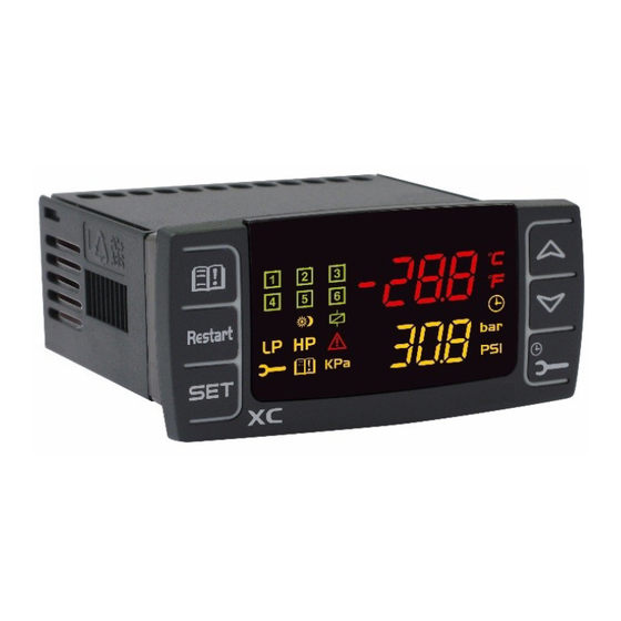
- Page 1 ÷÷ EC2-XC645CX (v. 3.5)
- Page 2 EC2-XC645CX HECK THE SW REL OF THE GENERAL WARNING LEASE READ BEFORE USING THIS MANUAL AFETY RECAUTIONS GENERAL DESCRIPTION COMPONENTS RELATED TO THE EC2-XC645CX CWC15KIT CWC30KIT: WIRING KITS CABCJ15 CABCJ30: 2 PIN CONNECTORS PT5N: 4÷20 PRESSURE TRANSDUCERS AND CABLE ASSEMBLIES...
- Page 3 18.1 IGITAL OMPRESSOR REGULATION 18.2 ROPORTIONAL BAND REGULATION ONLY FOR FANS 18.3 –A ONDENSER WITH NVERTER OR NALOG UTPUT ETTING 18.4 “ ” NALOG OUTPUT FREE ADDITIONAL FUNCTIONS 19.1 OMPRESSOR RUNNING PROOF FUNCTION 19.2 LOOD PROTECTION FUNCTION OI_EC2-XC645CX_A1_A2L_A3_EN_Rev01_866933.docx EC2-XC645CX 3/54...
- Page 4 19.3 UCTION SUPERHEAT MONITORING 19.4 OT GAS INJECTION VALVE ALARM LIST 20.1 YPES OF ALARMS AND SIGNALING MANAGED 20.2 UZZER MUTING 20.3 – LARM CONDITIONS SUMMARY TABLE TECHNICAL FEATURES PARAMETERS – DEFAULT VALUES OI_EC2-XC645CX_A1_A2L_A3_EN_Rev01_866933.docx EC2-XC645CX 4/54...
-
Page 5: Before Proceeding
Check the sw rel. of the EC2-XC645CX Look at the SW rel. of XC64D printed on the label of the controller. If the SW release is 3.5, proceed with this manual otherwise contact Emerson to get the right manual. GENERAL WARNING... -
Page 6: General Description
GENERAL DESCRIPTION The EC2-XC645CX is designed to manage both compressors and fans in a condensing system such as a pack. The compressors can be digital scroll, simple, multistage. It’s possible to manage suction circuit and condenser. Control is by means of a neutral zone or proportional band and is based on the pressure or temperature sensed in the LP suction (compressors) and HP (condenser) circuits. - Page 7 XJ485CX: TTL / RS485 serial converter The XJ485CX is a TTL/RS485 external converter. Insert it into the TTL receptacle to convert the TTL output into a RS485 (+) and (-) signal for the monitoring system MODBUS_RTU compatible. (XWEB). OI_EC2-XC645CX_A1_A2L_A3_EN_Rev01_866933.docx EC2-XC645CX 7/54...
-
Page 8: Wiring & Electrical Connections
Always use a class 2 transformer with minimum power 5 VA such as TF5. • Terminals [21-22], [23-24], [25-26], [27-28] are provided with JST 2 PINS connectors, they • require the CABCJ15 (1.5 m) or CABCJ30 (3 m) wiring cables. OI_EC2-XC645CX_A1_A2L_A3_EN_Rev01_866933.docx EC2-XC645CX 8/54... -
Page 9: Probe Connection
Pb3: (P3C = NTC): 4 - 3 Pb4: (P4C = Nt10) 27 - 28 Ratiometric transducers (0.5 - 4.5 VDC) Suction (P1C = 0-5) 5 (In); 4(+); 10 (gnd) Condenser (P2C = 0-5) 7 (In); 4(+); 10 (gnd) OI_EC2-XC645CX_A1_A2L_A3_EN_Rev01_866933.docx EC2-XC645CX 9/54... -
Page 10: Load Connections
SETTING 10-9 iF05 = LP1 25-26 iF06 = HP Note: *) The digital input 6 (25-26) requires the adapter CABCJ15 or CABCJ30 to be used. See par. Error! Reference source not found. Error! Reference source not found. OI_EC2-XC645CX_A1_A2L_A3_EN_Rev01_866933.docx EC2-XC645CX 10/54... -
Page 11: Analog Output Connection
2AOF: function How to connect monitoring system - RS485 Serial line The EC2-XC645CX can be connected to a monitoring system thanks to the serial output. To convert the TTL to RS485 signal, the XJ485CX has to be used. The XJ485CX is a TTL/RS485 external converter. -
Page 12: Mounting And Installation
29 x 71 mm hole, and fixed using the special brackets supplied. The ambient operating temperature range is between -10 - 60°C. Avoid locations subject to heavy vibration, corrosive gases or excessive dirt. The same applies to the probes. Ensure ventilation around the instrument. OI_EC2-XC645CX_A1_A2L_A3_EN_Rev01_866933.docx EC2-XC645CX 12/54... -
Page 13: First Installation
How to set the range of the pressure probes If an instrument with the following part number is used: EC2-XC645CX – xxxxF, it is pre-set to work with pressure probe with the following range: Probe 1: -0.5 -11.0 bar (relative pressure);... -
Page 14: User Interface
By holding it pressed for 3s the Maintaining menu is entered To enter the Alarm menu KEY COMBINATIONS To lock and unlock the keyboard. SET + To enter the programming mode. SET + To exit the programming mode. OI_EC2-XC645CX_A1_A2L_A3_EN_Rev01_866933.docx EC2-XC645CX 14/54... - Page 15 3. To see the fan set point, push again the SET key. 4. The Lower display will show the “SEtF” label, the Upper display will show the fan set point. EXIT: Push the SET key or wait for 30 without pressing any keys. OI_EC2-XC645CX_A1_A2L_A3_EN_Rev01_866933.docx EC2-XC645CX 15/54...
- Page 16 The “regulation filter” function calculates the average value of the pressure/ temperature during a PWM cycle and uses this value for the control algorithm. AO1: Percentage of the analog output 1 (4 – 20 mA or 0 – 10 V). This information is always available. OI_EC2-XC645CX_A1_A2L_A3_EN_Rev01_866933.docx EC2-XC645CX 16/54...
-
Page 17: Parameter Programming
5. Press “SET” to store the new value and move to the following parameter. EXIT: Press SET + UP or wait 15 s without pressing a key. NOTE: The new programming is stored even when the procedure is excited by waiting the time- out. OI_EC2-XC645CX_A1_A2L_A3_EN_Rev01_866933.docx EC2-XC645CX 17/54... - Page 18 4. Hold pushed the key for some seconds till the “rSt” label starts flashing and the lower display shows zero. EXIT: Push the CLOCK key or wait 30 seconds. NOTE: If the SET key is released within 2 seconds, the controller reverts to display the running hours of the selected loads. OI_EC2-XC645CX_A1_A2L_A3_EN_Rev01_866933.docx EC2-XC645CX 18/54...
-
Page 19: Keyboard Locking
2. The “POF” message will be displayed, and the keyboard is locked. At this point it is only possible to view the set point or enter the HACCP menu. 15.2 To unlock the keyboard Keep the o and n keys pressed together for more than 3s till the “POn” flashing message appears. OI_EC2-XC645CX_A1_A2L_A3_EN_Rev01_866933.docx EC2-XC645CX 19/54... -
Page 20: List Of Parameters
“Hot Key” and vice-versa. LIST OF PARAMETERS 17.1 Plant dimensioning and type of regulation. The EC2-XC645CX is pre-set to drive a Digital Scroll compressor. The relay 15-17 is set to manage the Digital compressor, while the TRIAC output 17-19 drives its solenoid valve. - Page 21 = dgS oA2 = CPr1 oA3 = CPr1 oA4 = CPr1 oA6 = nu Plant with 1 compressor and 3 fans: oA1 = dgS oA2 = FAn oA3 = FAn oA4 = FAn oA6 = nu OI_EC2-XC645CX_A1_A2L_A3_EN_Rev01_866933.docx EC2-XC645CX 21/54...
- Page 22 NOTE: The digital scroll compressor is always started as first and switched off as last. In any case, if it is locked because of safety timers, another compressor is started to maintain the pressure in the regulation band. OI_EC2-XC645CX_A1_A2L_A3_EN_Rev01_866933.docx EC2-XC645CX 22/54...
-
Page 23: Probe Configuration
(3P04 - 61.0 bar; 3P04 – 885 PSI; 3P04 – 6100 kPA) Probe 3 calibration the range depends on the dEU parameter: dEU = bar or °C: -12.0 - 12.0; dEU = PSI or °F: -20 - 20; dEU = kPA: -999 - 999; OI_EC2-XC645CX_A1_A2L_A3_EN_Rev01_866933.docx EC2-XC645CX 23/54... - Page 24 NOTE: Digital input 7 is enabled only when P4C = NP, otherwise it operates as temprature probe iP01 Digital input 1 polarity (10 - 13): oP: the digital input is activated by opening the contact. CL: the digital input is activated by closing the contact. OI_EC2-XC645CX_A1_A2L_A3_EN_Rev01_866933.docx EC2-XC645CX 24/54...
-
Page 25: Display And Measurement Unit
PMU parameter (bar, PSI or kPA) Measurement unit for temperature: it is used only with dEU = tMP, and it set the measurement unit for parameters referred to temperature/pressure. °C = Celsius degree °F = Fahrenheit degree OI_EC2-XC645CX_A1_A2L_A3_EN_Rev01_866933.docx EC2-XC645CX 25/54... - Page 26 Minimum time between 2 following switching ON of the same compressor (0 - 255 min). oFon Minimum time between the switching off of a compressor and the following switching on. (0 – 255 min). Note: usually onon is greater than oFon. OI_EC2-XC645CX_A1_A2L_A3_EN_Rev01_866933.docx EC2-XC645CX 26/54...
- Page 27 Maximum set point for fan: The measurement unit depends on dEU parameter. It sets the maximum acceptable value for set point. OI_EC2-XC645CX_A1_A2L_A3_EN_Rev01_866933.docx EC2-XC645CX 27/54...
- Page 28 (FA04 – HAF bar; -50.0 – HAF °C; FA04 – HAF PSI; -58 – HAF °F) It’s independent from the set point. When the value LAF is reached the LA2 alarm is enabled, (possibly after the AFd delay time). OI_EC2-XC645CX_A1_A2L_A3_EN_Rev01_866933.docx EC2-XC645CX 28/54...
-
Page 29: Suction Superheat
ASH9 = P3 the probe to calculate the superheat (SH) is the probe P3 (term. 38 - 42) ASH9 = P4 the probe to calculate the superheat (SH) is the probe P4 (term. 22 - 23). In this case also the parameter P4C must be set as nt10 or nt86. OI_EC2-XC645CX_A1_A2L_A3_EN_Rev01_866933.docx EC2-XC645CX 29/54... - Page 30 1 - 100 = it sets the maximum percentage variation per minute of the analog output. Percentage of analog output in case of probe failure: (0 - 100 %) Maximum analog output percentage when silence mode function is enabled. (0 - 100) OI_EC2-XC645CX_A1_A2L_A3_EN_Rev01_866933.docx EC2-XC645CX 30/54...
- Page 31 = buzzer is used in case of alarm Serial address (1 - 247); It is used in monitoring system. Software release for internal use. Sub-Release firmware for internal use. Parameter table code: readable only. Access to Pr2 parameter level OI_EC2-XC645CX_A1_A2L_A3_EN_Rev01_866933.docx EC2-XC645CX 31/54...
- Page 32 EG: Plant with 2 compressors (one of them digital) e 2 fans default configuration with PP11, PP30 pressure transducers: oA1 = dGS oA2 = CPr1, oA3 = FAn, oA4 = FAn, dGty = SCrL 24VAC The pressure is adjusted by a PI regulation. OI_EC2-XC645CX_A1_A2L_A3_EN_Rev01_866933.docx EC2-XC645CX 32/54...
- Page 33 This procedure continues with all active loads, with the shutdowns spaced out by the doF time setting. d. When only the DGS remains on, at the end of the doF time the DGS is shut down too. OI_EC2-XC645CX_A1_A2L_A3_EN_Rev01_866933.docx EC2-XC645CX 33/54...
- Page 34 = dGS oA2 = 6dG oA3 = FAn, oA4 = FAn, dGty = StrM 24VAC The pressure is adjusted by a PI regulation, following the same logic of the digital scroll see previous paragraphs: 18.1.2 and 18.1.3. OI_EC2-XC645CX_A1_A2L_A3_EN_Rev01_866933.docx EC2-XC645CX 34/54...
- Page 35 For a proper functioning of the DGS, it’s recommended a minimum activation time of 2 seconds. PMA It limits the percentage of the DGS activation during a tdS period according to the formula: ((Pbd * PMA) / 100) * tdS. OI_EC2-XC645CX_A1_A2L_A3_EN_Rev01_866933.docx EC2-XC645CX 35/54...
- Page 36 Example 4 Fans: oA2 = FAn; oA3 = FAn; oA4 = FAn; oA6 = FAn: rot = yES rotation enabled ALL LOADS ON Set+Pb/2 Set+Pb/4 S ET F Set-Pb/4 Set-Pb/2 ALL LOADS OFF OI_EC2-XC645CX_A1_A2L_A3_EN_Rev01_866933.docx EC2-XC645CX 36/54...
- Page 37 Set the time of the analog output at max after start up EI: Aot = 3 s Set the max % variation per min (MP) At last set also the percentage of analog output in case of probe failure: (0 - 100%) SAO OI_EC2-XC645CX_A1_A2L_A3_EN_Rev01_866933.docx EC2-XC645CX 37/54...
- Page 38 Set the end scale temperature by UAO parameter, at which correspond the maximum value of analog output Set the max % variation per min (MPM) g. At last set also the percentage of analog output in case of probe failure: (0 – 100 %) SAO OI_EC2-XC645CX_A1_A2L_A3_EN_Rev01_866933.docx EC2-XC645CX 38/54...
-
Page 39: Additional Functions
Alarm recovers as soon as the safety timers of the compressor (onon, ofon) are over, and compressor come back available for regulation. After 5 consecutive alarms, the alarms move from automatic restart to manual restart and it must be reset by Keyboard, of by switching off and on the controller. OI_EC2-XC645CX_A1_A2L_A3_EN_Rev01_866933.docx EC2-XC645CX 39/54... - Page 40 If the compressors are activated in fix sequence, (Sty = no), and the compressor that has to be activated is locked by safety timers, the relay set as flood protection is switched on till the safety timers are over. OI_EC2-XC645CX_A1_A2L_A3_EN_Rev01_866933.docx EC2-XC645CX 40/54...
- Page 41 ASH1 time ALSH The superheat is less Regulation depends Automatic: superheat than: SH< ASH2 for on ASH4: when superheat: alarm ASH3 time ASH4 = no: regulation SH> ASH5 + ASH2 not affected. ASH4 = yes: regulation is stopped. OI_EC2-XC645CX_A1_A2L_A3_EN_Rev01_866933.docx EC2-XC645CX 41/54...
-
Page 42: Alarm List
Second probe presence Probe for analog output When these parameters are set in wrong way an alarm message is generated: the label A12 is shown on the upper display, while the lower display the following messages are shown: OI_EC2-XC645CX_A1_A2L_A3_EN_Rev01_866933.docx EC2-XC645CX 42/54... - Page 43 Probe For SH oA4 = HGi), but the probe to If the hot gas injection valve is not present, set detected th superheat is oA2 or oA3 or oA4 different from HGi. missed: ASH9 = nP OI_EC2-XC645CX_A1_A2L_A3_EN_Rev01_866933.docx EC2-XC645CX 43/54...
- Page 44 Recovery depends on ALMr parameter: With ALMr = no The instrument restart the standard operating mode when the input is disabled. With ALMr = yES manual recover for the alarms of compressors and fans. Push the DOWN key for 3 seconds. OI_EC2-XC645CX_A1_A2L_A3_EN_Rev01_866933.docx EC2-XC645CX 44/54...
- Page 45 Manually (if PEn activation happened in the PEi time) When the input is disable: a. hold pressed the Restart (DOWN) key for 3 seconds or b. turn off and on the instrument. - The compressors restarts working according to the working algorithm. OI_EC2-XC645CX_A1_A2L_A3_EN_Rev01_866933.docx EC2-XC645CX 45/54...
- Page 46 C1-HA Maximum Suction Signaling only Automatically: as soon as the pressure or pressure pressure or temperature reaches the (HAL - differential) (temperature) temperature value. alarm higher than (differential = 0.3 bar or 1°C) compressors HAL value. section OI_EC2-XC645CX_A1_A2L_A3_EN_Rev01_866933.docx EC2-XC645CX 46/54...
- Page 47 ALSH Low superheat The superheat Regulation Automatic: allarm is less than: depends on when superheat: SH< ASH2 for ASH4: SH> ASH5 + ASH2 ASH3 time. ASH4 = no: regulation not affected. ASH4 = yes: regulation is stopped. OI_EC2-XC645CX_A1_A2L_A3_EN_Rev01_866933.docx EC2-XC645CX 47/54...
-
Page 48: Technical Features
Analogue output accuracy: 3 % full scale Serial output : TTL standard Communication protocol: ModBus – RTU Purpose of control: operating control Construction of control: incorporated control, intended to be used in Class I or Class II equipment. OI_EC2-XC645CX_A1_A2L_A3_EN_Rev01_866933.docx EC2-XC645CX 48/54... - Page 49 -12.0 - 12.0°C; -20 - 20°F; -12.0 - 12.0 bar; FCAL P2 probe offset -200 - 200 PSI; -999 - 999 kPa P3 probe setting np., Cur, tEn, nt10, nt86 (4 – 20 mA, 0-5 V, ntc) OI_EC2-XC645CX_A1_A2L_A3_EN_Rev01_866933.docx EC2-XC645CX 49/54...
- Page 50 Configurable digital input i1F iP07 OP, CL polarity (22 - 23): Digital input delay for i1F = oA1 0 - 255 s or Co1 Digital input delay for i2F = oA1 0 - 255 s & Co1 OI_EC2-XC645CX_A1_A2L_A3_EN_Rev01_866933.docx EC2-XC645CX 50/54...
- Page 51 -50.0 - 50.0°C; -90 - 90°F Energy saving for compressors -20.0 - 20.0 bar; -300 – 300 PSI; regulation -2000 – 2000 kPa Minimum delay between 2 OnOn switching on of the same 0 - 255 min. compressor OI_EC2-XC645CX_A1_A2L_A3_EN_Rev01_866933.docx EC2-XC645CX 51/54...
- Page 52 Pressure switch activations time 0 - 255 min. Number of compressors ON with 0 - 6 faulty probe DLT high temperature alarm 110.0 0 - 180°C; 32 - 356°F threshold DLT high temperature alarm 0 - 15 min. delay OI_EC2-XC645CX_A1_A2L_A3_EN_Rev01_866933.docx EC2-XC645CX 52/54...
- Page 53 -2000 – 2000 kPa Analogue output 1 working mode Cur, tEn Analog output 1 function Nu, InC1, InC2, InF Frequency compressor always InCP no, yES starts at first Reference probe 1 analogue nP(0), P3(1), P4(2) output (only function FREE) OI_EC2-XC645CX_A1_A2L_A3_EN_Rev01_866933.docx EC2-XC645CX 53/54...
- Page 54 Serial address 1 - 247 Release firmware Readable only Sub-release firmware Readable only Parameter table code Readable only 3210 Pr2 access Readable only Emerson Climate Technologies GmbH Pascalstrasse 65 I 52076 Aachen I Germany www.climate.emerson.com/en-gb OI_EC2-XC645CX_A1_A2L_A3_EN_Rev01_866933.docx EC2-XC645CX 54/54...