
Related Manuals for Emerson Daniel Senior Orifice Fitting Series


Summary of Contents for Emerson Daniel Senior Orifice Fitting Series
- Page 1 Owner and operator manual P a r t N u m b e r : 3 - 9 0 0 8 - 0 0 1, R e v . M J a n u a r y 2 0 1 5 Daniel Senior Orifice Fittings...
-
Page 3: Daniel Customer Service
+971 4 8118100 +971 4 8865465 E-mail • Customer Service: tech.service@emersonprocess.com • Customer Support: daniel.cst.support@emerson.com • Asia-Pacific: danielap.support@emerson.com • Europe: DanielEMA.CST@EmersonProcess.com Return Material Authorization (RMA) A Return Material Authorization (RMA) number must be obtained prior to returning any equipment for any reason. -
Page 4: Signal Words And Symbols
Signal words and symbols Pay special attention to the following signal words, safety alert symbols and statements: Safety alert symbol This is a safety alert symbol. It is used to alert you to potential physical injury hazards. Obey all safety messages that follow this symbol to avoid possible injury or death. Danger indicates a hazardous situation which, if not avoided, will result in death or serious injury. -
Page 5: Important Safety Instructions
Important safety instructions Daniel Measurement and Control, Inc. (Daniel) designs, manufactures and tests products to function within specific conditions. Because these products are sophisticated technical instruments, it is important that the owner and operation personnel strictly adhere both to the information printed on the product and to all instructions provided in this manual prior to installation, operation, and maintenance. - Page 6 Product Operation Personnel: • To prevent personal injury, personnel must follow all instructions of this manual prior to and during operation of the product. • Follow all warnings, cautions, and notices marked on, and supplied with, this product. • Verify that this is the correct instruction manual for your Daniel product. If this is not the correct documentation, contact Daniel at 1-713-827-6314.
-
Page 7: Notice
Notice THE CONTENTS OF THIS PUBLICATION ARE PRESENTED FOR INFORMATIONAL PURPOSES ONLY, AND WHILE EVERY EFFORT HAS BEEN MADE TO ENSURE THEIR ACCURACY, THEY ARE NOT TO BE CONSTRUED AS WARRANTIES OR GUARANTEES, EXPRESSED OR IMPLIED, REGARDING THE PRODUCTS OR SERVICES DESCRIBED HEREIN OR THEIR USE OR APPLICABILITY. -
Page 8: Warranty And Limitations
Warranty and Limitations 1. LIMITED WARRANTY: Subject to the limitations contained in Section 2 herein, Daniel Measurement & Control, Inc. (“Daniel”) warrants that the licensed firmware embodied in the Goods will execute the programming instructions provided by Daniel, and that the Goods manufactured by Daniel will be free from defects in materials or workmanship under normal use and care and Services will be performed by trained personnel using proper equipment and instrumentation for the particular Service provided. -
Page 9: Table Of Contents
Owner and operator manual Table of Contents 3-9008-001 Rev M January 2015 Contents Daniel customer service Signal words and symbols Important safety instructions Notice Warranty and Limitations Section 1: Introduction Purpose of this manual ................1 Description ....................1 1.2.1 Technical data .................... - Page 10 Table of Contents Owner and operator manual January 2015 3-9008-001 Rev M Section 4: Orifice plate installation and removal instructions Plate change procedure ................49 Selecting an appropriate plate change procedure ......... 50 Orifice plate (13) change operation ............. 52 4.3.1 “Quick change”...
- Page 11 Owner and operator manual List of Tables 3-9008-001 Rev M January 2015 List of Tables Table 1-1 Daniel Senior Orifice Fitting sizes 2” thru 8” 150-900 ............8 Table 1-2 Daniel Senior Orifice Fittings sizes 2” thru 8” 1500 and 2” thru 6” 2500 ......12 Table 1-3 Daniel Senior Orifice Fittings sizes 8”...
- Page 12 List of Tables Owner and operator manual January 2015 3-9008-001 Rev M List of Tables...
- Page 13 Owner and operator manual List of Figures 3-9008-001 Rev M January 2015 List of Figures Figure 1-1 Daniel Senior Orifice Fitting - Flangenek option ............2 Figure 1-2 Daniel Senior Orifice Fitting drawing 2”-8” 150-900............7 Figure 1-3 Daniel Senior Orifice Fitting drawing sizes 2”-8” 1500 and 2” -6” 2500 ....... 11 Figure 1-4 Daniel Senior Orifice Fitting drawing sizes 8”-12”...
- Page 14 List of Figures Owner and operator manual January 2015 3-9008-001 Rev M List of Figures...
-
Page 15: Purpose Of This Manual
Owner and operator manual Section 1: Introduction January 2015 3-9008-001 Rev M Section 1: Introduction 13 14 Purpose of this manual Daniel Measurement & Control Inc. designed this manual to guide owners and personnel in the installation, operation and maintenance of the Daniel Senior Orifice Fitting. -
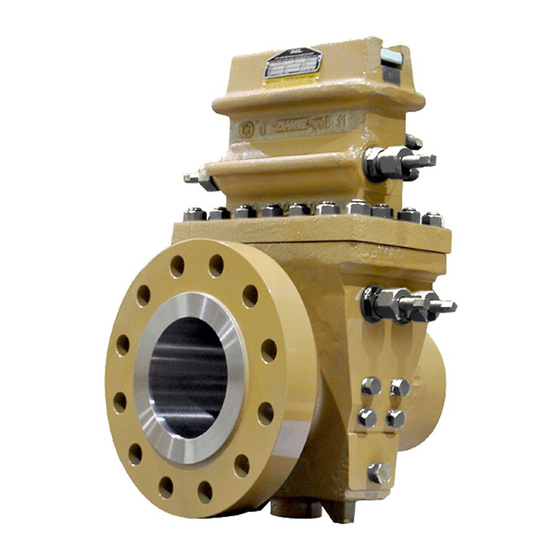
Page 16: Figure 1-1 Daniel Senior Orifice Fitting - Flangenek Option
Section 1: Introduction Owner and operator manual January 2015 3-9008-001 Rev M Figure 1-1 Daniel Senior Orifice Fitting - Flangenek option Therefore, using a Senior may eliminate the need for bypass piping, valves, and other fittings necessary with conventional orifice fitting installations. Maintenance technicians can replace and repair all parts of the Senior, including the slide valve assembly, without removing the Body (4) from the line (refer to Section 3:... - Page 17 Owner and operator manual Section 1: Introduction January 2015 3-9008-001 Rev M Products bearing the “CE” mark are designed and manufactured in compliance with the European Union Pressure Equipment Directive (PED) 97/23/EC. Refer to the “Daniel Orifice Fittings Installation and Operating Instructions specific to the Pressure Equipment Directive”, Part Number 3-9008-002.
-
Page 18: Technical Data
Section 1: Introduction Owner and operator manual January 2015 3-9008-001 Rev M 1.2.1 Technical data Follow all the safety and equipment limits recommended in 1.2.1 Technical data of this manual. It is the owner’s and/or purchaser’s responsibility to comply with these parameters. PERSONAL PROTECTION HAZARD Follow all parameters for the Senior Orifice Fitting indicated below. - Page 19 Owner and operator manual Section 1: Introduction January 2015 3-9008-001 Rev M Components: • Maintenance interval: Exercise components monthly. Examine components during orifice plate changes or at least once a year. Replace components when worn or damaged. • Seal replacement: Examine seals and gaskets during orifice plate inspections or at least once a year.
- Page 20 Section 1: Introduction Owner and operator manual January 2015 3-9008-001 Rev M Interface parameters: • Replacement parts: Use only replacement parts specified by Daniel. Unauthorized parts and procedures can affect this product’s performance and place the safe operation of your process at risk. •...
-
Page 21: Specifications
Owner and operator manual Section 1: Introduction January 2015 3-9008-001 Rev M Specifications 1.3.1 Daniel Senior Orifice Fitting sizes 2”-8” 150-900 Figure 1-2 Daniel Senior Orifice Fitting drawing 2”-8” 150-900 Specifications... -
Page 22: Table 1-1 Daniel Senior Orifice Fitting Sizes 2" Thru 8" 150-900
Section 1: Introduction Owner and operator manual January 2015 3-9008-001 Rev M All Parts on Daniel Senior Orifice Fittings may be replaced or repaired without removing the Senior body from the line. Table 1-1 Daniel Senior Orifice Fitting sizes 2” thru 8” 150-900 Number required Parts and materials Size... - Page 23 Owner and operator manual Section 1: Introduction January 2015 3-9008-001 Rev M Table 1-1 Daniel Senior Orifice Fitting sizes 2” thru 8” 150-900 Number required Parts and materials Size Item no. Description Material 2” 3” 4” 6” 8” Cast Carbon Steel Slide Valve Springs 316 Stainless Steel Slide Valve Carrier Guide...
- Page 24 Section 1: Introduction Owner and operator manual January 2015 3-9008-001 Rev M Notes:Table 1-1 All Daniel Senior Orifice Fittings are supplied with pipe plugs on one side only. If additional quantities are required, please contact the factory directly. Locations of Equalizer Valve (1), Bleeder Valve (10B), and Grease Gun (23) may differ from diagrams shown in this manual.
-
Page 25: Figure 1-3 Daniel Senior Orifice Fitting Drawing Sizes 2"-8" 1500 And 2" -6" 2500
Owner and operator manual Section 1: Introduction January 2015 3-9008-001 Rev M 1.3.2 Daniel Senior Orifice Fitting sizes 2”-8” 1500 and 2”-6” 2500 Figure 1-3 Daniel Senior Orifice Fitting drawing sizes 2”-8” 1500 and 2” -6” 2500 Daniel Senior Orifice Fitting sizes 2”-8” 1500 and 2”-6” 2500... -
Page 26: Table 1-2 Daniel Senior Orifice Fittings Sizes 2" Thru 8" 1500 And 2" Thru 6" 2500
Section 1: Introduction Owner and operator manual January 2015 3-9008-001 Rev M All Parts on Daniel Senior Orifice Fittings may be replaced or repaired without removing the Senior body from the line. Table 1-2 Daniel Senior Orifice Fittings sizes 2” thru 8” 1500 and 2” thru 6” 2500 Number required Parts and materials Size... - Page 27 Owner and operator manual Section 1: Introduction January 2015 3-9008-001 Rev M Table 1-2 Daniel Senior Orifice Fittings sizes 2” thru 8” 1500 and 2” thru 6” 2500 Number required Parts and materials Size Item no. Description Material 2” 3” 4”...
- Page 28 Section 1: Introduction Owner and operator manual January 2015 3-9008-001 Rev M Table 1-2 Daniel Senior Orifice Fittings sizes 2” thru 8” 1500 and 2” thru 6” 2500 Number required Parts and materials Size Item no. Description Material 2” 3” 4”...
- Page 29 Owner and operator manual Section 1: Introduction January 2015 3-9008-001 Rev M Notes:Table 1-2 All Daniel Senior Orifice Fittings are supplied with pipe plugs on one side only. If additional quantities are required, please contact the factory directly. Locations of Equalizer Valve (1), Bleeder Valve (10B), and Grease Gun (23) may differ from diagrams shown in this manual.
-
Page 30: Daniel Senior Orifice Fitting Sizes 8"-12" 250011
Section 1: Introduction Owner and operator manual January 2015 3-9008-001 Rev M 1.3.3 Daniel Senior Orifice Fitting sizes 8”-12” 2500 Figure 1-4 Daniel Senior Orifice Fitting drawing sizes 8”-12” 2500 Daniel Senior Orifice Fitting sizes 8”-12” 2500... -
Page 31: Table 1-3 Daniel Senior Orifice Fittings Sizes 8" Thru 12" 2500
Owner and operator manual Section 1: Introduction January 2015 3-9008-001 Rev M All parts on Daniel Senior Orifice Fittings may be replaced or repaired without removing the Daniel Senior Orifice Fitting body from the line. Table 1-3 Daniel Senior Orifice Fittings sizes 8” thru 12” 2500 Number required Parts and materials... - Page 32 Section 1: Introduction Owner and operator manual January 2015 3-9008-001 Rev M Table 1-3 Daniel Senior Orifice Fittings sizes 8” thru 12” 2500 Number required Parts and materials Size Item no. Description Material 8” 10” 12” 17E-HP Stuffing Box Spring Retainer 316 Stainless Steel 17F-HP Stuffing Box Spring...
- Page 33 Owner and operator manual Section 1: Introduction January 2015 3-9008-001 Rev M Notes:Table 1-3 All Daniel Senior Orifice Fittings are supplied with pipe plugs on one side only. If additional quantities are required, please contact the factory directly. Locations of Equalizer Valve (1), Bleeder Valve (10B), and Grease Gun (23) may differ from diagrams shown in this manual.
-
Page 34: Daniel Senior Orifice Fitting Sizes 10"-16" 150-900
Section 1: Introduction Owner and operator manual January 2015 3-9008-001 Rev M 1.3.4 Daniel Senior Orifice Fitting sizes 10”-16” 150-900 Figure 1-5 Daniel Senior Orifice Fitting drawing sizes 10”-16” 150-900 Daniel Senior Orifice Fitting sizes 10”-16” 150-900... -
Page 35: Table 1-4 Daniel Senior Orifice Fitting Sizes 10" Thru 16" 150-900
Owner and operator manual Section 1: Introduction January 2015 3-9008-001 Rev M All Parts on Daniel Senior Orifice Fittings may be replaced or repaired without removing the Daniel Senior Orifice Fitting body from the line. Table 1-4 Daniel Senior Orifice Fitting sizes 10” thru 16” 150-900 Number required Parts and materials Size... - Page 36 Section 1: Introduction Owner and operator manual January 2015 3-9008-001 Rev M Table 1-4 Daniel Senior Orifice Fitting sizes 10” thru 16” 150-900 Number required Parts and materials Size Item no. Description Material 10” 12” 14” 16” Bleeder Valve (complete): CS (ZP) w/ 410 Stainless Steel Bleeder Valve Nipple Clamping Bar Screw...
- Page 37 Owner and operator manual Section 1: Introduction January 2015 3-9008-001 Rev M Notes:Table 1-4 All Daniel Senior Orifice Fittings are supplied with pipe plugs on one side only. If additional quantities are required, please contact the factory directly. Locations of Equalizer Valve (1), Bleeder Valve (10B), and Grease Gun (23) may differ from diagrams shown in this manual.
-
Page 38: Daniel Senior Orifice Fitting Sizes 10"-16" 1500
Section 1: Introduction Owner and operator manual January 2015 3-9008-001 Rev M 1.3.5 Daniel Senior Orifice Fitting sizes 10”-16” 1500 Figure 1-6 Daniel Senior Orifice Fitting drawing sizes 10”-16” 1500 Daniel Senior Orifice Fitting sizes 10”-16” 1500... -
Page 39: Table 1-5 Daniel Senior Orifice Fitting Sizes 10" Thru 16" 1500
Owner and operator manual Section 1: Introduction January 2015 3-9008-001 Rev M All Parts on Daniel Senior Orifice Fittings may be replaced or repaired without removing the Daniel Senior Orifice Fitting body from the line. Table 1-5 Daniel Senior Orifice Fitting sizes 10” thru 16” 1500 Number required Parts and materials Size... - Page 40 Section 1: Introduction Owner and operator manual January 2015 3-9008-001 Rev M Table 1-5 Daniel Senior Orifice Fitting sizes 10” thru 16” 1500 Number required Parts and materials Size Item no. Description Material 10” 12” 14” 16” Slide Valve Springs 316 Stainless Steel Slide Valve Carrier Guide 316 Stainless Steel...
- Page 41 Owner and operator manual Section 1: Introduction January 2015 3-9008-001 Rev M Notes:Table 1-5 All Daniel Senior Orifice Fittings are supplied with pipe plugs on one side only. If additional quantities are required, please contact the factory directly. Locations of Equalizer Valve (1), Bleeder Valve (10B), and Grease Gun (23) may differ from diagrams shown in this manual.
- Page 42 Section 1: Introduction Owner and operator manual January 2015 3-9008-001 Rev M Daniel Senior Orifice Fitting sizes 10”-16” 1500...
-
Page 43: General Information
Owner and operator manual Section 2: Installation January 2015 3-9008-001 Rev M Section 2: Installation 21TOP (14) Figure 2-1 Daniel Senior Orifice Fitting component identification General information The Daniel Senior Orifice Fitting is an essential element in an orifice plate flow measurement system. -
Page 44: Storage
Section 2: Installation Owner and operator manual January 2015 3-9008-001 Rev M When assembling a flow measurement system that will contain a Daniel Senior Orifice Fitting, particular attention should be paid to the requirements for permanent joining of components. This will be to ensure optimal measurement performance and successful pressure test results. Referencing an appropriate measurement code (AGA-3, ISO 5167, etc.) will aid in this assembly. -
Page 45: Severe Service Conditions
Owner and operator manual Section 2: Installation January 2015 3-9008-001 Rev M Severe service conditions If product owners or personnel expect that the Senior will encounter severe conditions (environment where there is likely to be an accumulation of sediment for any cause), then Daniel recommends the removal of the Drain Valve Plug (30) near the bottom of the Senior and the installation of a blow down valve in its place (refer to Section 3: Maintenance... -
Page 46: Internal Corrosive Environments
Section 2: Installation Owner and operator manual January 2015 3-9008-001 Rev M 2.5.2 Internal corrosive environments For Daniel Senior Orifice Fittings located in internal corrosive environments, Daniel recommends that product owners purchase a Senior appropriate for the intended service. Daniel offers the Daniel Senior Orifice Fitting in a number of trims (Refer to Table 1-1 thru... -
Page 47: Commissioning Daniel Senior Orifice Fitting Installation
Owner and operator manual Section 2: Installation January 2015 3-9008-001 Rev M Install the Senior in any horizontal line with the plate access opening in a vertical up position or with the Senior rotated left or right to give a horizontal opening position. Daniel Senior Orifice Fittings to 12"... - Page 48 Section 2: Installation Owner and operator manual January 2015 3-9008-001 Rev M • Confirm the Operating Wrench (2) operational clearances for the Plate Carrier (8DM or 8DMC) extraction, and meter tap equipment draw clearance. • Check shipment to verify that the shipping kit contains an Operating Wrench (2), Grease Gun (23), Indicator Plate (5A-marked “LH”...
-
Page 49: Commissioning Line Pressure Test
Owner and operator manual Section 2: Installation January 2015 3-9008-001 Rev M With the slide valve in the fully opened position, follow these instructions: Rotate the Lower Plate Carrier Shaft (6) first. Rotate the Upper Plate Carrier Shaft (7) to remove the Plate Carrier (8DM or 8DMC). - Page 50 Section 2: Installation Owner and operator manual January 2015 3-9008-001 Rev M FLUID EXPLOSION HAZARD Never pressurize a unit above the limits recommended in Section 1.2.1: Technical data of this manual. Before pressurizing the Daniel Senior Orifice Fitting, confirm the maximum allowable operating pressure (MAOP) of each item in the system.
- Page 51 Owner and operator manual Section 2: Installation January 2015 3-9008-001 Rev M If a leak is detected, mark the leak area with a marker and reduce the pressure inside the Senior to 0 psig (0 bar). Tighten any fastener or connector adjacent to the leak area and repeat the leak test again.
-
Page 52: Orifice Plate Installation
Section 2: Installation Owner and operator manual January 2015 3-9008-001 Rev M 2.10 Orifice Plate Installation After completion of the commissioning line pressure test in Section 2.9, install and lower the Plate Carrier (8DM or 8DMC) and Orifice Plate Assembly (13) into the Body (4) to begin measurement operations. -
Page 53: Figure 2-3 Plate Carrier (8Dm Or 8Dmc) Plunger And Notch Location
Owner and operator manual Section 2: Installation January 2015 3-9008-001 Rev M Orient the 2”-8” Plate Carrier (8DMC) assembly with the notch down. The notch end of the 2”-8” Plate Carrier (8DMC) assembly must enter the Senior first. Important Install the Plate Carrier (8DM or 8DMC) assembly into the Senior with the gear rack facing downstream and the notched end down (refer to Figure 2-3 Figure... -
Page 54: Figure 2-4 Orientation Of Plate Carrier (8Dm Or 8Dmc) Prior To Installation
Section 2: Installation Owner and operator manual January 2015 3-9008-001 Rev M The diagram below depicts the proper orientation of the Plate Carrier (8DM or 8DMC) assembly prior to lowering it into the measurement position in the Senior. Figure 2-4 Orientation of Plate Carrier (8DM or 8DMC) Prior to Installation NOTES: The gear rack side of the Plate Carrier (8DM or 8DMC) assembly must face the downstream direction of flow. - Page 55 Owner and operator manual Section 2: Installation January 2015 3-9008-001 Rev M Install the Sealing Bar (9 or 9HP), the Sealing Bar Gasket (9A, 9A-HP or 9CF), and the Clamping Bar (12 or 12HP) in position on the Top (14) and tighten the Clamping Bar Screws (11).
- Page 56 Section 2: Installation Owner and operator manual January 2015 3-9008-001 Rev M Orifice Plate Installation...
-
Page 57: Normal Conditions
Owner and operator manual Section 3: Maintenance January 2015 3-9008-001 Rev M Section 3: Maintenance Normal conditions Under normal measurement conditions, Daniel recommends lubricating the slide valve and exercising several key components of the Daniel Senior Orifice Fitting every thirty days (refer to Section 3.1.2: Component Exercise). - Page 58 Section 3: Maintenance Owner and Operator Manual January 2015 3-9008-001 Rev M Remove the stem from the Grease Gun (23) and insert a Daniel lubricant stick into the Grease Gun (23). Step 1 Step 1A PRESSURIZED FLUID HAZARD Using the Grease Gun (23), inject grease into the slide valve seat channels at a rate of 4 to 6 turns per minute and only under the following conditions: •...
-
Page 59: Component Exercise
Owner and operator manual Section 3: Maintenance January 2015 3-9008-001 Rev M Step 2 Important By turning the stem of the Grease Gun (23) at a rate of 4 to 6 turns per minute, the lubricant is forced through the Slide Valve Seat (18) channels at a rate that allows the lubricant to travel freely, yet not separate the valve strip from the valve seat. - Page 60 Section 3: Maintenance Owner and Operator Manual January 2015 3-9008-001 Rev M slide valve should travel freely in both directions with light resistance. Leave the slide valve in the OPEN position. Important The following operation will affect the flowing differential and will be shown on any chart or instrument, keep records of differential, unless these instruments are isolated.
- Page 61 Owner and operator manual Section 3: Maintenance January 2015 3-9008-001 Rev M Remove the stem from the Grease Gun (23) with the Operating Wrench (2) and insert a Daniel lubricant stick into the Grease Gun (23). PRESSURIZED FLUID HAZARD Using the Grease Gun (23), inject grease into the slide valve seat channels at a rate of 4 to 6 turns per minute and only under the following conditions: •...
- Page 62 Section 3: Maintenance Owner and Operator Manual January 2015 3-9008-001 Rev M If at any point during the exercise of the components, the resistance encountered when turning a shaft is greater than the torque applied by hand using the Wrench (2), further inspection of the Senior is required.
-
Page 63: Orifice Plate Installation And Removal Instructions
Owner and operator manual Section 4: Orifice plate installation and removal instructions January 2015 3-9008-001 Rev M Section 4: Orifice plate installation and removal instructions Plate change procedure Follow these instructions during every plate change. FLUID EXPLOSION HAZARD Follow the instructions below to avoid inadvertent or accidental opening of the slide valve and the propulsion of fluid or internal components from the Top (4). -
Page 64: Selecting An Appropriate Plate Change Procedure
Section 4: Orifice plate installation and removal instructions Owner and operator manual January 2015 3-9008-001 Rev M Selecting an appropriate plate change procedure EXPLOSION HAZARD The Daniel Senior Orifice Fitting contains fluid at elevated pressure. Make sure to follow the instructions below for proper installation and removal of the plate. -
Page 65: Table 4-1 Plate Change Procedure Selection For Grease Assisted Slide Valves And
Owner and operator manual Section 4: Orifice plate installation and removal instructions January 2015 3-9008-001 Rev M In order to assist the operator in determining the safest and most efficient means to perform the Orifice Plate (13) change on a Senior equipped with a grease assisted slide valve, Daniel prepared two plate change procedures that an operator may select from. -
Page 66: Orifice Plate (13) Change Operation
Section 4: Orifice plate installation and removal instructions Owner and operator manual January 2015 3-9008-001 Rev M Orifice plate (13) change operation Important In order to perform a safe and efficient plate change operation with a Senior, the on-site personnel must evaluate both the service and environmental conditions prior to beginning this operation. -
Page 67: Quick Change" Procedure
Owner and operator manual Section 4: Orifice plate installation and removal instructions January 2015 3-9008-001 Rev M 4.3.1 “Quick change” procedure You may use the Quick change procedure for Daniel Senior Orifice Fittings equipped with an O- Ring (10E) soft seated valve and for Seniors equipped with a grease-assisted slide valve. Important Do not use this procedure if it cannot be finished in less than 15 minutes. - Page 68 Section 4: Orifice plate installation and removal instructions Owner and operator manual January 2015 3-9008-001 Rev M Prior to performing any maintenance or Orifice Plate (13) installation and removal operations on the Senior, personnel must visually confirm the presence of the Indicator Plate (5A) on the Slide Valve Shaft (5) and the Indicator Pointer (5B) on the Body (4).
- Page 69 Owner and operator manual Section 4: Orifice plate installation and removal instructions January 2015 3-9008-001 Rev M FLUID EXPLOSION HAZARD Follow the instructions below to avoid inadvertent or accidental opening of the slide valve and the propulsion of fluid or internal components from the Top (4). Failure to do so will result in serious injury or death.
- Page 70 Section 4: Orifice plate installation and removal instructions Owner and operator manual January 2015 3-9008-001 Rev M Wait several seconds while the pressure in the Top (14) equalizes to that of the Body (4). Using the Operating Wrench (2) rotate the Slide Valve Shaft (5) until it stops and the OPEN position specified on the Indicator Plate (5A) is in line with the Indicator Pointer (5B).
- Page 71 Owner and operator manual Section 4: Orifice plate installation and removal instructions January 2015 3-9008-001 Rev M Move the Operating Wrench (2) from the Lower Plate Carrier Shaft (6) located in the Body (4) on the Upper Plate Carrier Shaft (7) located in the Top (14). Rotate the Upper Plate Carrier Shaft (7) located in the Top (14) until the Plate Carrier (8DM or 8DMC) stops against the Sealing Bar (9, 9HP).
- Page 72 Section 4: Orifice plate installation and removal instructions Owner and operator manual January 2015 3-9008-001 Rev M Open the Bleeder Valve (10B) with the Operating Wrench (2). PRESSURIZED FLUID HAZARD When opening the bleeder valve (10B) or venting the Top (14) thru the bleeder valve (10B), direct the released pressurized fluid and/or gas to safe area away from any individual in accordance with local environment regulations.
- Page 73 Owner and operator manual Section 4: Orifice plate installation and removal instructions January 2015 3-9008-001 Rev M Step 11 Step 11A PRESSURIZED FLUID HAZARD Using the Grease Gun (23), inject grease into the slide valve seat channels at a rate of 4 to 6 turns per minute and only under the following conditions: •...
- Page 74 Section 4: Orifice plate installation and removal instructions Owner and operator manual January 2015 3-9008-001 Rev M Step 12 Important By turning the stem of the Grease Gun (23) at a rate of 4 to 6 turns per minute, the lubricant is forced through the Slide Valve Seat (18) channels at a rate that allows the lubricant to travel freely, yet not separate the valve strip from the valve seat.
- Page 75 Owner and operator manual Section 4: Orifice plate installation and removal instructions January 2015 3-9008-001 Rev M Monitor the fluid/gas pressure in the Top (14) until it is equal to ambient conditions. Important Once the Top (14) is equal to ambient conditions, the 15 minute countdown to remove and install the Orifice Plate Carrier (8DM or 8DMC) begins.
- Page 76 Section 4: Orifice plate installation and removal instructions Owner and operator manual January 2015 3-9008-001 Rev M Step 15 Slide the Clamping Bar (12 or 12HP) containing the Clamping Bar Screws (11), the Sealing Bar (9 or 9HP) from the Top (14). Step 16-17 Remove the Sealing Bar Gasket (9A, 9A-HP or 9CF) from the Top (14).
- Page 77 Owner and operator manual Section 4: Orifice plate installation and removal instructions January 2015 3-9008-001 Rev M continue to rotate the Upper Plate Carrier Shaft (7) until the Upper Plate Carrier Shaft (7) gears and the Plate Carrier (8DM or 8DMC) gear rack ratchet. Step 18 Remove the Orifice Plate Carrier (8DM or 8DMC) from the Top (14) and perform the scheduled work on the Orifice Plate (13) and Orifice Plate Carrier (8DM or 8DMC).
- Page 78 Section 4: Orifice plate installation and removal instructions Owner and operator manual January 2015 3-9008-001 Rev M Once the Orifice Plate Carrier (8DM or 8DMC) is aligned, rotate the Upper Plate Carrier Shaft (7) with the Operating Wrench (2), in a direction to lower the Orifice Plate Carrier (8DM or 8DMC) into the Top (14) until all of the Orifice Plate Carrier (8DM or 8DMC) is below the Sealing Bar Gasket (9A, 9A-HP or 9CF) surface.
- Page 79 Owner and operator manual Section 4: Orifice plate installation and removal instructions January 2015 3-9008-001 Rev M Install the Sealing Bar (9 or 9HP) and the Clamping Bar (12 or 12HP) on to the Top (14). Tighten each Clamping Bar Screw (11), located on the Clamping Bar (12 or 12HP), to the torque recommended in this manual (refer to Section 5.3: Torque information.
- Page 80 Section 4: Orifice plate installation and removal instructions Owner and operator manual January 2015 3-9008-001 Rev M Using the Operating Wrench (2), rotate the Slide Valve Shaft (5) to the OPEN position. Step 29 Step 30 Rotate the Upper Plate Carrier Shaft (7) with the Operating Wrench (2) in the direction to lower the Orifice Plate Carrier (8DM or 8DMC) into the Body (4).
- Page 81 Owner and operator manual Section 4: Orifice plate installation and removal instructions January 2015 3-9008-001 Rev M Once the Orifice Plate Carrier (8DM or 8DMC) is positioned in the Body (4), turn the Slide Valve Shaft (5) using the Operating Wrench (2) into the CLOSED position. Step 32 Step 33 Close the Equalizer Valve (1).
- Page 82 Section 4: Orifice plate installation and removal instructions Owner and operator manual January 2015 3-9008-001 Rev M Open the Bleeder Valve (10B) to vent the Top (14). Step 34 Steps 35 and 36 are ONLY required for Seniors equipped with grease assisted, metal-to-metal slide valves.
- Page 83 Owner and operator manual Section 4: Orifice plate installation and removal instructions January 2015 3-9008-001 Rev M Step 35 Step 35A PRESSURIZED FLUID HAZARD Using the Grease Gun (23), inject the grease into the slide valve seat channels at a rate of 4 to 6 turns per minute and only under the following conditions: •...
- Page 84 Section 4: Orifice plate installation and removal instructions Owner and operator manual January 2015 3-9008-001 Rev M Step 36 Important By turning the stem of the Grease Gun (23) at a rate of 4 to 6 turns per minute, the lubricant is forced through the Slide Valve Seat (18) channels at a rate that allows the lubricant to travel freely, yet not separate the valve strip from the valve seat.
-
Page 85: Extended Time" Procedure
Owner and operator manual Section 4: Orifice plate installation and removal instructions January 2015 3-9008-001 Rev M Step 37 The Daniel Senior Orifice Fitting is now ready for measurement. 4.3.2 “Extended time” procedure This procedure is for the grease-assisted slide valves when the procedure takes over 15 minutes. However, it is acceptable for soft-seated valves. -
Page 86: Figure 4-4 Indicator Plate (5A) And Pointer (5B)
Section 4: Orifice plate installation and removal instructions Owner and operator manual January 2015 3-9008-001 Rev M TOXIC EXPLOSION HAZARD Do not perform any of the following steps if the Indicator Plate, the Indicator Pointer, or both are not assembled on the Senior. Call Daniel Customer Service for assistance in obtaining replacement components, and follow the instructions provided in Section 2.8: Commissioning Daniel Senior Orifice Fitting... - Page 87 Owner and operator manual Section 4: Orifice plate installation and removal instructions January 2015 3-9008-001 Rev M In preparation for the plate removal and installation process, the operator must evaluate the meter system to determine the amount of time between the Top (14) fluid evacuation and the plate change to the full replacement of the Clamping Bar (12 or 12HP), the Sealing Bar (9 or 9HP), and the Sealing Bar Gasket (9A, 9A-HP or 9CF) back on the Top (14).
- Page 88 Section 4: Orifice plate installation and removal instructions Owner and operator manual January 2015 3-9008-001 Rev M Procedure: To remove the Orifice Plate (13) from the Daniel Senior Orifice Fitting, the operator must first balance the pressure between the Top (14) and the Body (4). Open the Equalizer Valve (1) one half to two full turns using the Operating Wrench (2).
- Page 89 Owner and operator manual Section 4: Orifice plate installation and removal instructions January 2015 3-9008-001 Rev M Continue to rotate the Lower Plate Carrier Shaft (6) located on the Body (4) until the Upper Plate Carrier Shaft (7) located in the Top (14) begins to rotate. Step 5 Step 6 Move the Operating Wrench (2) from the Lower Plate Carrier Shaft (6) located in the...
- Page 90 Section 4: Orifice plate installation and removal instructions Owner and operator manual January 2015 3-9008-001 Rev M Step 9 Step 10 Open the Bleeder Valve (10B) with the Operating Wrench (2). PRESSURIZED FLUID HAZARD When opening the bleeder valve (10B) or venting the Top (14) thru the bleeder valve (10B), direct the released pressurized fluid and/or gas to safe area away from any individual in accordance with local environment regulations.
- Page 91 Owner and operator manual Section 4: Orifice plate installation and removal instructions January 2015 3-9008-001 Rev M Step 11 Step 11A PRESSURIZED FLUID HAZARD Using the Grease Gun (23), Inject the grease into the slide valve seat channels at a rate of 4 to 6 turns per minute and only under the following conditions: •...
- Page 92 Section 4: Orifice plate installation and removal instructions Owner and operator manual January 2015 3-9008-001 Rev M Step 12 Important By turning the stem of the Grease Gun (23) at a rate of 4 to 6 turns per minute, the lubricant is forced through the Slide Valve Seat (18) channels at a rate that allows the lubricant to travel freely, yet not separate the valve strip from the valve seat.
- Page 93 Owner and operator manual Section 4: Orifice plate installation and removal instructions January 2015 3-9008-001 Rev M Monitor the fluid/gas pressure in the Top (14) until it is equal to ambient conditions. RELEASE OF FLUIDS OR COMPONENTS HAZARD The Clamping Bar (12 or 12HP) may not be securely in place. Sudden release of fluid or internal components may occur.
- Page 94 Section 4: Orifice plate installation and removal instructions Owner and operator manual January 2015 3-9008-001 Rev M Once the Clamping Bar Screws (11) are loose, rotate the Upper Plate Carrier Shaft (7) located in the Top (14) with the Operating Wrench (2), until the Plate Carrier (8DM or 8DMC) taps against the Sealing Bar (9 or 9HP) freeing it from the Top (14).
- Page 95 Owner and operator manual Section 4: Orifice plate installation and removal instructions January 2015 3-9008-001 Rev M continue to rotate the Upper Plate Carrier Shaft (7) until the Upper Plate Carrier Shaft (7) gears and the Plate Carrier (8DM or 8DMC) gear rack ratchet. Step 18 Remove the Orifice Plate Carrier (8DM or 8DMC) from the Top (14) and perform the scheduled work on the Orifice Plate (13) and Orifice Plate Carrier (8DM or 8DMC).
- Page 96 Section 4: Orifice plate installation and removal instructions Owner and operator manual January 2015 3-9008-001 Rev M Step 20 Step 21 EXPLOSION HAZARD Follow the instructions in this manual to assure that the Sealing Bar Gasket (9A, 9A-HP or 9CF), the Sealing Bar (9 or 9HP) and the Clamping Bar (12 or 12HP) provide a pressure barrier between the line pressure and the atmosphere.
- Page 97 Owner and operator manual Section 4: Orifice plate installation and removal instructions January 2015 3-9008-001 Rev M Step 22 Important At this stage in the operational procedure, the Senior is at the following conditions: a) The Equalizer Valve (1) is closed. b) The Bleeder Valve (10B) closed.
- Page 98 Section 4: Orifice plate installation and removal instructions Owner and operator manual January 2015 3-9008-001 Rev M Open the Bleeder Valve (10B) with the Operating Wrench (2) Step 24 Steps 25 and 26 are ONLY required for the Seniors equipped with grease assisted, metal-to- metal slide valves.
- Page 99 Owner and operator manual Section 4: Orifice plate installation and removal instructions January 2015 3-9008-001 Rev M Return the stem to the Grease Gun (23) and begin turning it clockwise by hand into the Grease Gun (23) until resistance is felt. Once this is done, use the supplied Operating Wrench (2) to continue to turn the stem at a rate of 4 to 6 turns per minute.
- Page 100 Section 4: Orifice plate installation and removal instructions Owner and operator manual January 2015 3-9008-001 Rev M Important By turning the stem of the Grease Gun (23) at a rate of 4 to 6 turns per minute, the lubricant is forced through the Slide Valve Seat (18) channels at a rate that allows the lubricant to travel freely, yet not separate the valve strip from the valve seat.
- Page 101 Owner and operator manual Section 4: Orifice plate installation and removal instructions January 2015 3-9008-001 Rev M Step 28 Step 29 Once the Clamping Bar Screws (11) are loose, it may be necessary to use the Operating Wrench (2) to tap against the Sealing Bar (9 or 9HP) freeing it from the Top (14). Slide the Clamping Bar (12 or 12HP) containing the Clamping Bar Screws (11), the Sealing Bar (9) from the Top (14).
- Page 102 Section 4: Orifice plate installation and removal instructions Owner and operator manual January 2015 3-9008-001 Rev M Insert the Orifice Plate Carrier (8DM or 8DMC) into the Top (14) until the Upper Plate Carrier Shaft (7) gears and plate carrier gear rack mesh. With the Operating Wrench (2), rotate the Upper Plate Carrier Shaft (7), located in the Top (14), a minimum of one quarter turns OPPOSITE of the direction required to lower the Orifice Plate Carrier (8DM or 8DMC) into the Top (14).
- Page 103 Owner and operator manual Section 4: Orifice plate installation and removal instructions January 2015 3-9008-001 Rev M EXPLOSION HAZARD Follow the instructions in this manual to assure that the Sealing Bar Gasket (9A, 9A-HP or 9CF), the Sealing Bar (9 or 9HP) and the Clamping Bar (12 or 12HP) provide a pressure barrier between the line pressure and the atmosphere.
- Page 104 Section 4: Orifice plate installation and removal instructions Owner and operator manual January 2015 3-9008-001 Rev M Step 37 Step 38 Close the Bleeder Valve (10B). Open the Equalizer Valve (1) one-half to two turns with the Operating Wrench (2). Step 39 Step 40 Wait several seconds for the Top (14) to reach pressure equilibrium with the line...
- Page 105 Owner and operator manual Section 4: Orifice plate installation and removal instructions January 2015 3-9008-001 Rev M Step 41 Step 42 Rotate the Upper Plate Carrier Shaft (7) located in the Top (14) with the Operating Wrench (2) in the direction to lower the Orifice Plate Carrier (8DM or 8DMC) into the Body (4).
- Page 106 Section 4: Orifice plate installation and removal instructions Owner and operator manual January 2015 3-9008-001 Rev M Important Resistance to turning will be present when the Orifice Plate Carrier (8DM or 8DMC) is approaching its proper measurement position due to friction between the Senior Body (4) and the Orifice Plate (13) seal.
- Page 107 Owner and operator manual Section 4: Orifice plate installation and removal instructions January 2015 3-9008-001 Rev M Open the Bleeder Valve (10B) to vent the Top (14). Step 46 Step 47 and 48 are ONLY required for Seniors equipped with grease assisted, metal-to-metal slide valves.
- Page 108 Section 4: Orifice plate installation and removal instructions Owner and operator manual January 2015 3-9008-001 Rev M Step 47 Step 47A PRESSURIZED FLUID HAZARD Using the Grease Gun (23), inject the grease into the slide valve seat channels at a rate of 4 to 6 turns per minute and only under the following conditions: •...
- Page 109 Owner and operator manual Section 4: Orifice plate installation and removal instructions January 2015 3-9008-001 Rev M Return the stem to the Grease Gun (23) and begin turning it clockwise by hand into the Grease Gun (23) until resistance is felt. Once this is done, use the supplied Operating Wrench (2) to continue to turn the stem at a rate of 4 to 6 turns per minute.
- Page 110 Section 4: Orifice plate installation and removal instructions Owner and operator manual January 2015 3-9008-001 Rev M Close the Bleeder Valve (10B). Step 49 The Daniel Senior Orifice Fitting is now ready for measurement. “Extended time” procedure...
-
Page 111: Recommended Spare Parts For One-Year Operation
Owner and operator manual Section 5: Supplemental information January 2015 3-9008-001 Rev M Section 5: Supplemental information Recommended spare parts for one-year operation Table 5-1 Recommended spare parts Item No. Weight Description Material Quantity 150-2500 Shaft CS (ZP) 150-600 Orifice Plate Sealing Unit Nitrile 900-2500 Orifice Plate Sealing Unit... -
Page 112: Lubricant Information
Section 5: Supplemental information Owner and operator manual January 2015 3-9008-001 Rev M Lubricant information Product owners and operating personnel select the Daniel Senior Orifice Fitting for use in a wide variety of flow measurement services around the world. Information and experience gathered indicate that measurement service conditions do have a profound effect on the metal-to-metal slide valve sealing performance. -
Page 113: Figure 5-1 Standard Grease - Type 1
Owner and operator manual Section 5: Supplemental information January 2015 3-9008-001 Rev M Figure 5-1 Standard grease - Type 1 Pressure (psig) v. Temperature (°F) STANDARD GREASE - TYPE 1 - Part Number:1-213-04-001 OPTIMUM SEALING RANGE WITH NITROGEN FOR A 3" ANSI 600 SENIOR FITTING UNDER LABORATORY CONDITIONS. -
Page 114: Figure 5-2 Sour Grease - Type 2
Section 5: Supplemental information Owner and operator manual January 2015 3-9008-001 Rev M Figure 5-2 Sour grease - Type 2 Pressure (psig) v. Temperature (°F) SOUR GAS GREASE - TYPE 2 - Part Number:1-213-04-102 OPTIMUM SEALING RANGE WITH NITROGEN FOR A 3" ANSI 600 SENIOR FITTING UNDER LABORATORY CONDITIONS. -
Page 115: Figure 5-3 Carbon Dioxide Grease - Type 3
Owner and operator manual Section 5: Supplemental information January 2015 3-9008-001 Rev M Figure 5-3 Carbon dioxide grease - Type 3 Pressure (psig) v. Temperature (°F) CARBON DIOXIDE GREASE - TYPE 3 - Part Number:1-213-04- 101 OPTIMUM SEALING RANGE WITH NITROGEN FOR A 3" ANSI 600 SENIOR FITTING UNDER LABORATORY CONDITIONS. -
Page 116: Figure 5-4 High Temperature Grease - Type 4
Section 5: Supplemental information Owner and operator manual January 2015 3-9008-001 Rev M Figure 5-4 High temperature grease - Type 4 Pressure (psig) v. Temperature (°F) HIGH TEMPERATURE GREASE - TYPE 4 - Part Number:1-213- 04-103 OPTIMUM SEALING RANGE WITH NITROGEN FOR A 3" ANSI 600 SENIOR FITTING UNDER LABORATORY CONDITIONS. -
Page 117: Torque Information
Owner and operator manual Section 5: Supplemental information January 2015 3-9008-001 Rev M Torque information Daniel utilizes several joint assemblies constructing the Senior. To successfully pass all factory tests, factory personnel torque each fastener in the joint assembly to contain pressure and seal the unit. -
Page 118: Table 5-3 Clamping Bar Screw (11) Quantity And Torque Requirements
Section 5: Supplemental information Owner and operator manual January 2015 3-9008-001 Rev M Table 5-3 Clamping bar screw (11) quantity and torque requirements Required torque (ft. - lbs) Number of Nominal size (in.) ANSI Class screws Screw size Minimum Maximum 1/2”-13 1/2”-13 1/2”-13... - Page 119 Owner and operator manual Section 5: Supplemental information January 2015 3-9008-001 Rev M Table 5-3 Clamping bar screw (11) quantity and torque requirements Required torque (ft. - lbs) Number of Nominal size (in.) ANSI Class screws Screw size Minimum Maximum 1/2”-13 1/2”-13 1/2”-13...
-
Page 120: Figure 5-5 Torque Pattern Sequences
Section 5: Supplemental information Owner and operator manual January 2015 3-9008-001 Rev M Figure 5-5 Torque pattern sequences Joint assembly procedures... -
Page 121: Table 5-4 Seat Screw Torque Lbf-Ft
Owner and operator manual Section 5: Supplemental information January 2015 3-9008-001 Rev M Table 5-4 Seat Screw Torque LBF-FT Torque (lbf-ft) Size STD Trim 2”-8” STD Trim 10” STD Trim 12” +: 316, Monel & all AASG Important Daniel calculated the torque values below based on the following design parameters: •... - Page 122 Section 5: Supplemental information Owner and operator manual January 2015 3-9008-001 Rev M Table 5-5 Daniel Senior Orifice Fitting Body(4) / Top (14) stud torque FT-LBS Torque Size (in.) ANSI class No. of screws Screw size Minimum Maximum 3/4” - 16 3/4”...
- Page 123 Owner and operator manual Section 5: Supplemental information January 2015 3-9008-001 Rev M Table 5-5 Daniel Senior Orifice Fitting Body(4) / Top (14) stud torque FT-LBS Torque Size (in.) ANSI class No. of screws Screw size Minimum Maximum 3/4” - 16 3/4”...
-
Page 124: Plate And Valve Carrier Clearances
Section 5: Supplemental information Owner and operator manual January 2015 3-9008-001 Rev M Plate and valve carrier clearances Table 5-6 Plate carrier to valve carrier clearances (inches) Minimum Maximum Line size clearance clearance .006 .018 .006 .018 .006 .018 .006 .018 .006 .018... -
Page 125: Material List
Owner and operator manual Section 5: Supplemental information January 2015 3-9008-001 Rev M 5.5.2 Material List The field technician will need to verify that all materials necessary for the retro-fit are included in the parts kit prior to beginning this procedure. Below is a breakdown of those parts and quantities (refer to Figure 5-6 for pictorial reference). -
Page 126: Disassembly
Section 5: Supplemental information Owner and operator manual January 2015 3-9008-001 Rev M 5.5.3 Disassembly Important It is not necessary to remove the Senior from the process line to facilitate these instructions. Removing the Daniel Senior Orifice Fitting should only be done at the discretion of the end user and after completing Step 1, below. - Page 127 Owner and operator manual Section 5: Supplemental information January 2015 3-9008-001 Rev M Store these items in a safe place for reuse later (remove the plate/seal assembly from the Plate Carrier (8DM or 8DMC) and store as a separate item). Mark four places minimum on the Body (4) and Top (14) crown flanges for match marks, one each per side (six marks preferred, two each per long side and one each per short side).
-
Page 128: Slide Valve Removal
Section 5: Supplemental information Owner and operator manual January 2015 3-9008-001 Rev M 5.5.4 Slide valve removal 2" - 14" Only - From inside the slide valve cavity of the Body (4), remove the Slide Valve Strip (3), Slide Valve Carrier (17), Slide Valve Springs (15) and Slide Valve Carrier Guides (16). These items will not be reused. -
Page 129: Senior Fittings 2"-8" For "Api-14.3
Owner and operator manual Section 5: Supplemental information January 2015 3-9008-001 Rev M 5.5.6 Senior Fittings 2"-8" for "API-14.3" Retrieve the Plate Carrier (8DM or 8DMC) from its safe storage. Reinstall it into the Senior Body (4) by first rotating the Lower Plate Carrier Shaft (6) "backwards"... -
Page 130: Senior Fittings 2"-8" Non "Api-14.3" & All 10" Thru 12
Section 5: Supplemental information Owner and operator manual January 2015 3-9008-001 Rev M 5.5.7 Senior Fittings 2"-8" Non "API-14.3" & all 10" thru 12" Retrieve the Plate Carrier (8DM or 8DMC) from its safe storage. Reinstall it into the Senior Body (4) by first rotating the Lower Plate Carrier Shaft (6) “backwards”... - Page 131 Owner and operator manual Section 5: Supplemental information January 2015 3-9008-001 Rev M Re-assemble the Top (14) as instructed below. Retrieve the Top (14) from its safe storage. Verify that the gaskets surfaces (sealing bar region of tee-slot and the crown flange) have been cleaned of all residue. Place the Top (14) on a clean, sturdy surface with the crown flange facing upward.
- Page 132 Section 5: Supplemental information Owner and operator manual January 2015 3-9008-001 Rev M LIFTING HAZARD The field technician should always use mechanical assistance when lifting the Top (14). Failure to do so may result in serious injury. Using a jib crane or equivalent, gently lower the Top (14) onto the Body (4). Make certain that the match up lines on the crown flanges of the Top (14) and Body (4) line up as close as possible.
-
Page 133: Table
Owner and operator manual Section 5: Supplemental information January 2015 3-9008-001 Rev M Rotate the Slide Valve Shaft (5) to move the soft seat slide valve assembly into its full “open” position. Install the balance of the stud bolt Hex Nuts (32) and tighten to “snug” only. Apply torque to the Hex Nuts (32) in a crisscross fashion, working from the center of the crown flange outward. - Page 134 Section 5: Supplemental information Owner and operator manual January 2015 3-9008-001 Rev M Apply line pressure to the Senior and verify that the gasket joints of the Sealing Bar (9 or 9HP)/Top (14) and the crown flanges of the Body are not leaking. Close the Equalizer Valve (1) and rotate the Slide Valve Shaft (5) to close the Soft Seat Slide Valve assembly.
-
Page 135: Figure 5-6 Daniel Senior Orifice Fitting
Owner and operator manual Section 5: Supplemental information January 2015 3-9008-001 Rev M Figure 5-6 Daniel Senior Orifice Fitting Refer to Table 5-7 Section 5: Supplemental information for item numbers and part descriptions Important Fittings manufactured after July 1985 use these stuffing box and bearing plug parts. The parts are interchangeable to prior dated fittings, but may require minor field modification (shortening) of the sleeves only. -
Page 136: Figure 5-7 Stuffing Box And Bearing Plug
Section 5: Supplemental information Owner and operator manual January 2015 3-9008-001 Rev M Figure 5-7 Stuffing box and bearing plug Senior Fittings 2"-8" Non "API-14.3" & all 10" thru 12"... - Page 138 © 2015 Daniel Measurement and Control, Inc., All rights reserved T + 44-1786-433400 The Emerson logo is a trademark and service mark of Emerson Electric Co. Daniel Measurement Middle East: Africa: Dubai, UAE and Control, Inc. (Daniel) are Emerson Process Management business units. The Daniel name and T +971-4-811-8100 logo are trademarks of Daniel Industries, Inc.