Baumer Hubner Berlin HOG 10 Mounting And Operating Instructions
Incremental encoder (twin encoder) with fischer connect mating connector
Hide thumbs
Also See for Hubner Berlin HOG 10:
- Installation and operating instructions manual (40 pages) ,
- Mounting and operating instructions (40 pages) ,
- Installation and operating instructions manual (32 pages)
Table of Contents
Advertisement
Quick Links
Advertisement
Table of Contents

Related Manuals for Baumer Hubner Berlin HOG 10


Summary of Contents for Baumer Hubner Berlin HOG 10
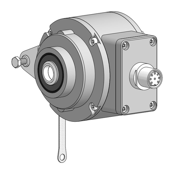
- Page 1 Montage- und Betriebsanleitung Mounting and operating instructions Option G HOG 10 (HOG 10 G) Inkrementaler Drehgeber (Zwillingsgeber) mit Fischer Connect Rundsteckverbinder Incremental encoder (Twin encoder) with Fischer Connect mating connector...
-
Page 2: Table Of Contents
Inhaltsverzeichnis Inhaltsverzeichnis Allgemeine Hinweise ..............................Betrieb in explosionsgefährdeten Bereichen ..................Sicherheitshinweise ..............................Vorbereitung .................................. Lieferumfang ..............................Zur Montage erforderlich (nicht im Lieferumfang enthalten) ........... Zur Demontage erforderlich (nicht im Lieferumfang enthalten) ..........Erforderliches Werkzeug (nicht im Lieferumfang enthalten) ........... Montage .................................. - Page 3 Table of contents Table of contents General notes ................................Operation in potentially explosive environments ................. Security indications ..............................Preparation ..................................Scope of delivery ............................Required for mounting (not included in scope of delivery) ............Required for dismounting (not included in scope of delivery) ..........
-
Page 4: Allgemeine Hinweise
Gebrauchte Elektro- und Elektronikgeräte dürfen nicht im Hausmüll entsorgt werden. Das Produkt enthält wertvolle Rohstoffe, die recycelt werden können. Wenn immer möglich sollen Altgeräte lokal am entsprechenden Sammeldepot entsorgt werden. Im Bedarfsfall gibt Baumer den Kunden die Möglichkeit, Baumer-Produkte fachgerecht zu entsor- gen. Weitere Informationen siehe www.baumer.com. Achtung! Beschädigung des auf dem Gerät befindlichen Siegels... -
Page 5: General Notes
Disposal (environmental protection): Do not dispose of electrical and electronic equipment in household waste. The product contains valuable raw materials for recycling. Whenever possible, waste electrical and electronic equipment should be disposed locally at the authorized collection point. If necessary, Baumer gives customers the opportunity to dispose of Baumer products profession- ally. For further information see www.baumer.com. Warning! Damaging the seal on the device invalidates warranty. -
Page 6: Betrieb In Explosionsgefährdeten Bereichen
Betrieb in explosionsgefährdeten Bereichen Betrieb in explosionsgefährdeten Bereichen (nur bei Option ATEX) Das Gerät entspricht der Richtlinie 2014/34/EU für explosionsgefährdete Bereiche. Der Einsatz ist gemäß den Gerätekategorien 3 G (Ex-Atmosphäre Gas) und 3 D (Ex-Atmo- sphäre Staub) zulässig. Gerätekategorie 3 G: - Ex-Kennzeichnung: II 3 G Ex nA IIC T4 Gc - Normenkonformität:... -
Page 7: Operation In Potentially Explosive Environments
Operation in potentially explosive environments Operation in potentially explosive environments (only with option ATEX) The device complies with the directive 2014/34/EU for potentionally explosive atmospheres. It can be used in accordance with equipment categories 3 G (explosive gas atmosphere) and 3 D (explosive dust atmosphere). -
Page 8: Sicherheitshinweise
Sicherheitshinweise Sicherheitshinweise Verletzungsgefahr durch rotierende Wellen Haare und Kleidungsstücke können von rotierenden Wellen erfasst werden. • Vor allen Arbeiten alle Betriebsspannungen ausschalten und Maschinen stillsetzen. Zerstörungsgefahr durch elektrostatische Aufladung Die elektronischen Bauteile im Gerät sind empfindlich gegen hohe Spannungen. • Steckkontakte und elektronische Komponenten nicht berühren. •... -
Page 9: Security Indications
Security indications Security indications Risk of injury due to rotating shafts Hair and clothes may become tangled in rotating shafts. • Before all work switch off all voltage supplies and ensure machinery is stationary. Risk of destruction due to electrostatic charge Electronic parts contained in the device are sensitive to high voltages. -
Page 10: Vorbereitung
Vorbereitung / Preparation Vorbereitung Preparation Lieferumfang Scope of delivery Gehäuse Housing Einseitig offene Hohlwelle oder Konuswelle Blind hollow shaft or cone shaft with spanner mit Schlüsselfläche SW 17 mm flat 17 mm a/f Spannelement Clamping element (nur bei einseitig offene Hohlwelle) (only for blind hollow shaft) Stützblech für Drehmomentstütze Support plate for torque arm Sechskantschraube M6x18 mm, ISO 4017... -
Page 11: Zur Montage Erforderlich (Nicht Im Lieferumfang Enthalten)
Vorbereitung / Preparation Zur Montage erforderlich Required for mounting (nicht im Lieferumfang enthalten) (not included in scope of delivery) 15b 15c 3x 3x Drehmomentstütze, als Zubehör erhältlich: Torque arm, available as accessory: Bestellnummer Länge L, Version Order number Length L, version 11043628 67...70 mm, Standard 11043628 67...70 mm, standard... -
Page 12: Zur Demontage Erforderlich (Nicht Im Lieferumfang Enthalten)
Vorbereitung / Preparation Zur Demontage erforderlich Required for dismounting (nicht im Lieferumfang enthalten) (not included in scope of delivery) Montage-/Demontageset als Zubehör erhält- Mounting/dismounting kit available as acces- lich: Bestellnr. 11077087, bestehend aus ... sory: Order number 11077087, including ... Gewindestift M6x10 mm, ISO 7436 Setscrew M6x10 mm, ISO 7436 Zylinderschraube M8x45 mm, ISO 4762 Cylinder screw M8x45 mm, ISO 4762 Erforderliches Werkzeug... -
Page 13: Montage
Montage / Mounting Montage Mounting In den Bildern am Beispiel des Typs Pictures showing type HOG 10 as HOG 10. Gleiche Montageschritte bei Typ example. Same mounting steps for type HOG 10 G. HOG 10 G. Schritt 1 Step 1 10 mm 10 mm Schritt 2... -
Page 14: Schritt 3 - Einseitig Offene Hohlwelle
Montage / Mounting Schritt 3 - Einseitig offene Hohlwelle Step 3 - Blind hollow shaft Zentrierbohrung Center hole DIN 332-D, M6x16 mm 52 mm (40-52 mm) 53 mm 52 mm (40-52 mm) 16 mm * Siehe Seite 7 See page 7 Antriebswelle einfetten. -
Page 15: Schritt 3 - Konuswelle
Montage / Mounting Schritt 3 - Konuswelle Step 3 - Cone shaft Zentrierbohrung Center hole DIN 332-D, M6x16 mm 1:10 Antriebswelle einfetten. Lubricate drive shaft. Die Antriebswelle sollte einen The drive shaft should have as less möglichst kleinen Rundlauffehler runout as possible because this can aufweisen, da dieser zu einem otherwise result in an angle error, see Winkelfehler führen kann, siehe... -
Page 16: Schritt 4
Montage / Mounting Schritt 4 Step 4 Anzugsmoment einseitig offene Hohlwelle: Tightening torque blind hollow shaft: = 6 Nm Anzugsmoment Konuswelle: Tightening torque cone shaft: = 3...4 Nm 17 mm 5 mm 1.6x8 mm 10 mm * Siehe Seite 8 See page 8 MB071a - 11068613 Baumer_HOG10-HOG10G-FC_DE_EN_202011_MI_11068613 (20A2) -
Page 17: Schritt 5 - Drehmomentstütze
Montage / Mounting Schritt 5 - Drehmomentstütze Step 5 - Torque arm Die Montage der Drehmomentstütze The torque arm should be mounted sollte spielfrei erfolgen. Ein Spiel von free from clearance. A play of just beispielsweise ±0,03 mm entspricht ±0.03 mm, results in a runout of the einem Rundlauffehler des Gerätes von device of 0.06 mm. -
Page 18: Hinweis Zur Vermeidung Von Messfehlern
Montage / Mounting Hinweis zur Vermeidung von Messfeh- How to prevent measurement errors lern Für einen einwandfreien Betrieb des To ensure that the device operates cor- Gerätes ist eine korrekte Montage, ins- rectly, it is necessary to mount it accu- besondere auch der Drehmomentstütze, rately as described in section 5.1 to 5.6, notwendig, wie beschrieben in Abschnitt... -
Page 19: Schritt 6
Montage / Mounting Schritt 6 Step 6 3 mm Anzugsmoment: Tightening torque: = 2...3 Nm Schritt 7 Step 7 Fischer Connect Ansicht X Rundsteckverbinder mit siehe Abschnitt 7.3. Sensorkabel HEK 8, View X siehe Abschnitt 7.4. see section 7.3. Fischer Connect mating connector with sensor cable HEK 8, see section 7.4. -
Page 20: Abmessungen
Abmessungen / Dimensions Abmessungen Dimensions Einseitig offene Hohlwelle Blind hollow shaft 6.1.1 Standard 6.1.1 Standard Positive Drehrichtung Positive rotating direction Um 90° versetzt gezeichnet Drawing 90° rotated Zubehör Accessory 6.1.2 Option G: Zwillingsgeber HOG 10 G 6.1.2 Option G: Twin encoder HOG 10 G (74085) (74085) Positive Drehrichtung... -
Page 21: Konuswelle
Abmessungen / Dimensions Konuswelle Cone shaft 6.2.1 Standard 6.2.1 Standard Positive Drehrichtung Positive rotating direction Um 90° versetzt gezeichnet Drawing 90° rotated Zubehör Accessory 6.2.2 Option G: Zwillingsgeber HOG 10 G 6.2.2 Option G: Twin encoder HOG 10 G Positive Drehrichtung Positive rotating direction Um 90°... -
Page 22: Elektrischer Anschluss
Elektrischer Anschluss / Electrical connection Elektrischer Anschluss Electrical connection Beschreibung der Anschlüsse Terminal significance Betriebsspannung Voltage supply Masseanschluss (0V) Ground Erdungsanschluss (Gehäuse) Earth ground (housing) Ausgangssignal Kanal 1 Output signal channel 1 Ausgangssignal Kanal 1 invertiert Output signal channel 1 inverted Ausgangssignal Kanal 2 (90° versetzt zu Kanal 1) Output signal channel 2 (offset by 90°... -
Page 23: Anschlussbelegung Flanschdose Fischer Connect
Elektrischer Anschluss / Electrical connection Anschlussbelegung Flanschdose Connecting assignment flange connec- Fischer Connect tor Fischer Connect 7.3.1 D … 7.3.1 D … Ansicht X in Flanschdose, 8-polig, Buchsenkontakte, linksdrehend, siehe Abschnitt 5.9. View X into flange connector, 8-pin, female, CCW, see section 5.9. 7.3.2 D … I 7.3.2 D …... -
Page 24: Fischer Connect Rundsteckverbinder Mit Sensorkabel Hek 8
Elektrischer Anschluss / Electrical connection Fischer Connect Rundsteckverbinder Fischer Connect mating connector mit Sensorkabel HEK 8 with sensor cable HEK 8 Das Kabel sollte in einem Stück und ge- Continuous wiring without any splices or trennt von Stromkabeln verlegt werden. couplings should be used. Separate signal cables from power cables. -
Page 25: Demontage
Demontage / Dismounting Demontage Dismounting In den Bildern am Beispiel des Typs Pictures showing type HOG 10 as ex- HOG 10. Gleiche Demontageschritte bei ample. Same dismounting steps for type Typ HOG 10 G. HOG 10 G. Schritt 1 Step 1 3 mm Schritt 2 Step 2 10 mm... -
Page 26: Schritt 3
Demontage / Dismounting Schritt 3 Step 3 17 mm 5 mm Schritt 4 Step 4 0.8x4 mm * Siehe Seite 8 oder 9 See page 8 or 9 MB071a - 11068613 Baumer_HOG10-HOG10G-FC_DE_EN_202011_MI_11068613 (20A2) -
Page 27: Schritt 5
Demontage / Dismounting Schritt 5 Step 5 17 mm 6 mm Schritt 6 Step 6 * Siehe Seite 9 See page 9 MB071a - 11068613 Baumer_HOG10-HOG10G-FC_DE_EN_202011_MI_11068613 (20A2) -
Page 28: Technische Daten
Technische Daten Technische Daten Technische Daten - elektrisch • Betriebsspannung: 9...30 VDC (HTL-P, TTL - Version R) 5 VDC ±5 % (TTL) • Betriebsstrom ohne Last: ≤100 mA • Impulse pro Umdrehung: 300...5000 (je nach Bestellung) • Phasenverschiebung: 90° ±20° •... -
Page 29: Technical Data
Technical data Technical data Technical data - electrical ratings • Voltage supply: 9...30 VDC (HTL-P, TTL - version R) 5 VDC ±5 % (TTL) • Consumption w/o load: ≤100 mA • Pulses per revolution: 300...5000 (as ordered) • Phase shift: 90° ±20° • Duty cycle: 40...60 % • Reference signal: Zero pulse, width 90° •... -
Page 30: Zubehör
Zubehör / Accessories Zubehör Accessories • Drehmomentstütze Größe M6: • Torque arm size M6: Bestellnummer siehe Order number see Abschnitt 4.2 section 4.2 • Montageset für Drehmoment- • Mounting kit for torque arm stütze Größe M6 und Erdungs- size M6 and earthing strap: band: Bestellnummer 11077197 Order number 11077197 •... -
Page 31: Eu-Konformitätserklärung
Signature/nom/fonction Baumer_HOGx_OGx_POGx_FOGx_HMI_DE-EN-FR_CoC_81201236.docm/kwe Baumer Hübner GmbH P.O. Box 126943 ∙ D-10609 Berlin ∙ Max-Dohrn-Str. 2+4 ∙ D-10589 Berlin Phone +49 (0)30 69003-0 ∙ Fax +49 (0)30 69003-104 ∙ info@baumerhuebner.com ∙ www.baumer.com Sitz der Gesellschaft / Registered Office: Berlin, Germany ∙ Geschäftsführer / Managing Director: Dr. Oliver Vietze, Dr. Johann Pohany Handelsregister / Commercial Registry: AG Charlottenburg HRB 96409 ∙... - Page 32 Baumer Hübner GmbH P.O. Box 12 69 43 · 10609 Berlin, Germany Phone: +49 (0)30/69003-0 · Fax: +49 (0)30/69003-104 info@baumerhuebner.com · www.baumer.com/motion Version: 74085 MB071a - 11068613 Baumer_HOG10-HOG10G-FC_DE_EN_202011_MI_11068613 (20A2-02.11.2020)