Table of Contents
Advertisement
Quick Links
Advertisement
Table of Contents

Related Manuals for Baumer HUBNER BERLIN SAFETY HOG 10 + ESL


Summary of Contents for Baumer HUBNER BERLIN SAFETY HOG 10 + ESL
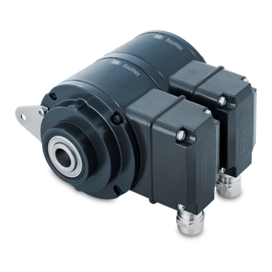
- Page 1 Montage- und Betriebsanleitung Installation and operating instructions HOG 10.2 M + ESL (Option redundant + EMS) HOG 10 + ESL Kombination Drehgeber mit integriertem elektronischen Drehzahlschalter Combination Encoder with integrated electronic speed switch...
-
Page 2: Table Of Contents
Inhaltsverzeichnis Inhaltsverzeichnis Allgemeine Hinweise ..............................Sicherheitshinweise ..............................Vorbereitung ..................................Lieferumfang Gerät ............................Lieferumfang Klemmenkästen ........................Zur Montage erforderlich (nicht im Lieferumfang enthalten) ............Zur Demontage erforderlich (nicht im Lieferumfang enthalten) ..........Erforderliches Werkzeug (nicht im Lieferumfang enthalten) ............Montage ....................................Schritt 1 ................................... - Page 3 Table of contents Table of contents General notes ................................... Security indications ..............................Preparation ..................................Scope of delivery of the device ........................Scope of delivery terminal boxes ......................Required for mounting (not included in scope of delivery) ............Required for dismounting (not included in scope of delivery) ............
-
Page 4: Allgemeine Hinweise
Allgemeine Hinweise Allgemeine Hinweise Zeichenerklärung: Gefahr Warnung bei möglichen Gefahren Hinweis zur Beachtung Hinweis zur Gewährleistung eines einwandfreien Betriebes des Produkts Information Empfehlung für die Produkthandhabung Die Kombination HOG 10 + ESL ist ein opto-elektronisches Prä zi sionsmessgerät, das mit Sorg- falt nur von technisch qualifiziertem Per sonal gehandhabt werden darf. -
Page 5: General Notes
General notes General notes Symbol guide: Danger Warnings of possible danger General information for attention Informations to ensure correct product operation Information Recommendation for product handling The combination HOG 10 + ESL is an opto electro nic precision measurement device which must be handled with care by skilled personnel only. -
Page 6: Sicherheitshinweise
Sicherheitshinweise Sicherheitshinweise Verletzungsgefahr durch rotierende Wellen Haare und Kleidungsstücke können von rotierenden Wellen erfasst werden. • Vor allen Arbeiten alle Betriebsspannungen ausschalten und Maschinen stillsetzen. Zerstörungsgefahr durch elektrostatische Aufladung Die elektronischen Bauteile in der Kombination sind empfindlich gegen hohe Spannungen. •... -
Page 7: Security Indications
Security indications Security indications Risk of injury due to rotating shafts Hair and clothes may become tangled in rotating shafts. • Before all work switch off all operating voltages and ensure machinery is stationary. Risk of destruction due to electrostatic charge Electronic parts contained in the combination are sensitive to high voltages. -
Page 8: Vorbereitung
Vorbereitung / Preparation Vorbereitung Preparation Lieferumfang Gerät Scope of delivery of the device 2) 3) Gehäuse Drehgeber HOG 10 Housing encoder HOG 10 Gehäuse Drehzahlschalter ESL Housing speed switch ESL Einseitig offene Hohlwelle oder Konuswelle Blind hollow shaft or cone shaft mit Schlüsselfläche SW 13 mm with spanner flat 13 mm a/f Spannelement... -
Page 9: Lieferumfang Klemmenkästen
Vorbereitung / Preparation Lieferumfang Klemmenkästen Scope of delivery terminal boxes Klemmenkastendeckel HOG 10 Terminal box cover HOG 10 Kombi-Torx-Schraube M4x32 mm Screw with torx and slotted drive M4x32 mm Kabelverschraubung M20x1,5 Cable gland M20x1.5 für Kabel ø5-13 mm for cable ø5-13 mm Platine mit Anschlussklemmen HOG 10, Board with connecting terminal HOG 10, siehe Abschnitt 6.1.1.3 und 6.1.4. -
Page 10: Zur Montage Erforderlich (Nicht Im Lieferumfang Enthalten)
Vorbereitung / Preparation Zur Montage erforderlich Required for mounting (nicht im Lieferumfang enthalten) (not included in scope of delivery) 18b 18c 3x 3x Drehmomentstütze, als Zubehör erhältlich, Torque arm, available as accessory, Bestellnummer (Länge L, Version): order number (length L, version): 11043628 (67-70 mm, Standard) 11043628... -
Page 11: Zur Demontage Erforderlich (Nicht Im Lieferumfang Enthalten)
Vorbereitung / Preparation Zur Demontage erforderlich Required for dismounting (nicht im Lieferumfang enthalten) (not included in scope of delivery) Montage-/Demontageset als Zubehör erhältlich, Mounting/dismounting kit available as accessory, Bestellnummer 11077087, bestehend aus: order number 11077087, including: Gewindestift M6x10, ISO 7436 (5,8 Vzk) Setscrew M6x10, ISO 7436 (5.8 Vzk) Zylinderschraube M8x45, ISO 4762 (A2) Cylinder screw M8x45, ISO 4762 (A2) -
Page 12: Montage
Montage / Mounting Montage Mounting Schritt 1 Step 1 10 mm 10 mm Schritt 2 Step 2 10 * TX 20 * Siehe Seite 5 oder 7 See page 5 or 7 MB071.2T2 - 11068774 Baumer_HOG10-ESL-T2_II_DE-EN (16A2) -
Page 13: Schritt 3 - Version Mit Einseitig Offener Hohlwelle
Montage / Mounting Schritt 3 - Version mit einseitig offener Step 3 - Blind hollow shaft version Hohlwelle Zentrierbohrung Center hole DIN 332-D, M6x16 mm 53 mm (35 mm bei/at ød = 20 mm) ød 16 mm 52 mm (40-52 mm) 20 mm 34 mm (25-34 mm) 16 mm... -
Page 14: Schritt 3 - Version Mit Konuswelle
Montage / Mounting Schritt 3 - Version mit Konuswelle Step 3 - Cone shaft version Zentrierbohrung Center hole DIN 332-D, M6x16 mm 1:10 Motorwelle einfetten! Lubricate motor shaft! Die Antriebswelle sollte einen mög- The drive shaft should have as less lichst kleinen Rundlauffehler aufwei- runout as possible because this can sen, da dieser zu einem Winkelfehler... -
Page 15: Schritt 4
Montage / Mounting Schritt 4 Step 4 5 mm 10 mm Zul. Anzugsmoment bei Version 1.6x8 mm mit einseitig offener Hohlwelle: Max. tightening torque for blind hollow shaft version: = 6 Nm Zul. Anzugsmoment bei Version mit Konuswelle: Max. tightening torque for cone shaft version: = 3-4 Nm * Siehe Seite 7... -
Page 16: Schritt 5 - Drehmomentstütze
Montage / Mounting Schritt 5 - Drehmomentstütze Step 5 - Torque arm Montage Drehmomentstütze The torque arm should be mounted sollte spielfrei erfolgen. Ein Spiel von free from clearance. A play of just beispielsweise ±0,03 entspricht ±0.03 mm, results in concentricity einem Rundlauffehler der Kombination error of the combination of 0.06 mm. -
Page 17: Hinweis Zur Vermeidung Von Messfehlern
Montage / Mounting Hinweis zur Vermeidung von Messfehlern How to prevent measurement errors Für einen einwandfreien Betrieb der To ensure that the combination operates Kombination ist ein korrekter Anbau, ins- correctly, it is necessary to mount it ac- besondere auch der Drehmomentstütze, curately as described in section 4.1 to 4.6, notwendig, wie beschrieben in Abschnitt which includes correct mounting of the... -
Page 18: Schritt 6
Montage / Mounting Schritt 6 Step 6 10 * PH 1 Zul. Anzugsmoment Max. tightening torque = 2-3 Nm Anbauhinweis Mounting instruction Wir empfehlen, die Kombination so zu It is recommended to mount the montieren, dass der Kabelanschluss combination with cable connection keinem direkten Wassereintritt aus- facing downward and being not expo- gesetzt ist. -
Page 19: Abmessungen
Abmessungen / Dimensions Abmessungen Dimensions Einseitig offene Hohlwelle Blind hollow shaft (74026, 74031, 74034, 74049, 74635, 74691) (74026, 74031, 74034, 74049, 74635, 74691) Um 90° versetzt gezeichnet Drawing 90° rotated Drehrichtung positiv Option EMS Positive rotating direction Option EMS + M Option M 13 mm Zubehör... -
Page 20: Elektrischer Anschluss
Elektrischer Anschluss / Electrical connection Elektrischer Anschluss Electrical connection Anschluss Drehgeber HOG 10 Connection encoder HOG 10 6.1.1 Kabelanschluss 6.1.1 Cable connection 6.1.1.1 Schritt 1 6.1.1.1 Step 1 TX 20 12c * 22 mm 6.1.1.2 Schritt 2 6.1.1.2 Step 2 TX 10 * Siehe Seite 6 See page 6... - Page 21 Elektrischer Anschluss / Electrical connection 6.1.1.3 Schritt 3 und 4 6.1.1.3 Step 3 and 4 12c * ø5-13 mm Ansicht siehe Abschnitt 6.1.4. Kabelschirm Cable shield View see section 6.1.4. * Siehe Seite 6 oder 7 See page 6 or 7 Zur Gewährleistung der angegebenen To ensure the specified protection Schutzart sind nur geeignete Kabel-...
- Page 22 Elektrischer Anschluss / Electrical connection Anschluss Drehgeber HOG 10 Connection encoder HOG 10 6.1.1 Kabelanschluss 6.1.1 Cable connection 6.1.1.4 Schritt 5 6.1.1.4 Step 5 Buchse D-SUB TX 10 zum Anschluss an Drehgebergehäuse siehe Abschnitt 6.1.1.5. Connector D-SUB (female) for connecting to encoder housing see section 6.1.1.5.
-
Page 23: Beschreibung Der Anschlüsse
Elektrischer Anschluss / Electrical connection 6.1.2 Beschreibung der Anschlüsse 6.1.2 Terminal significance Betriebsspannung (für den Drehgeber) +UB; + Voltage supply (for the encoder) Masseanschluss (für die Signale) ; ; GND; 0 V Ground (for the signals) Erdungsanschluss (Gehäuse) Earth ground (chassis) Ausgangssignal Kanal 1 K1;... -
Page 24: Klemmenbelegung
Elektrischer Anschluss / Electrical connection Anschluss Drehgeber HOG 10 Connection encoder HOG 10 6.1.4 Klemmenbelegung 6.1.4 Terminal assignment 6.1.4.1 Standard 6.1.4.1 Standard DN … I, DN … TTL, DN … R DN … I, DN … TTL, DN … R Ansicht X Max. -
Page 25: Led-Anzeige / Fehlerausgang (Option Ems - Enhanced Monitoring System)
Elektrischer Anschluss / Electrical connection 6.1.5 LED-Anzeige / Fehlerausgang 6.1.5 LED status / Error output (Option EMS - Enhanced Monitoring (Option EMS - Enhanced Monitoring System) System) Rotblinkend Signalfolge-, Nullimpuls- oder Flash light red Error of signal sequence, zero Impulszahlfehler (Fehlerausgang = pulse or pulses (Error output = HIGH-LOW-Wechsel) HIGH-LOW change) -
Page 26: Sensorkabel Hek 8 (Zubehör)
Sensorkabel HEK 8 (Zubehör) 6.1.6 Sensor cable HEK 8 (accessory) Es wird empfohlen, das Baumer Hübner Baumer Hübner sensor cable HEK 8 is Sensorkabel HEK 8 zu verwenden oder recommended. As a substitute a shielded ersatzweise ein geschirmtes, paarig ver- twisted pair cable should be used. -
Page 27: Anschluss Drehzahlschalter Esl
Elektrischer Anschluss / Electrical connection Anschluss Drehzahlschalter ESL Connection speeed switch ESL 6.2.1 Kabelanschluss 6.2.1 Cable connection 6.2.1.1 Schritt 1 6.2.1.1 Step 1 TX 20 22 mm 6.2.1.2 Schritt 2 6.2.1.2 Step 2 Um 180° wendbarer Klemmenkasten. Terminal box, turn by 180°. -
Page 28: Version Esl 90 (1 Internes Relais, 1 Schaltdrehzahl)
Elektrischer Anschluss / Electrical connection Anschluss Drehzahlschalter ESL Connection speeed switch ESL 6.2.2 Version ESL 90 6.2.2 Version ESL 90 (1 internes Relais, 1 Schaltdrehzahl) (1 internal relay, 1 switching speed) 6.2.2.1 Anschlussbelegung 6.2.2.1 Terminal assignment Ansicht Y Anschlussklemmen, siehe Abschnitt 6.2.1.2. View Y Connecting terminal, see section 6.2.1.2. -
Page 29: Version Esl 93 (3 Relais-Treiber, 3 Schaltdrehzahlen)
Elektrischer Anschluss / Electrical connection 6.2.3 Version ESL 93 6.2.3 Version ESL 93 (3 Relais-Treiber, 3 Schaltdrehzahlen) (3 relay driver, 3 switching speeds) 6.2.3.1 Anschlussbelegung 6.2.3.1 Terminal assignment Kabel: Ansicht Y 5-adrig abgeschirmt, Anschlussklemmen, Länge: ≤200 m bei siehe Abschnitt 6.2.1.2. 1 mm Querschnitt View Y... -
Page 30: Version Es 93 R Relaismodul (Zubehör)
Elektrischer Anschluss / Electrical connection Anschluss Drehzahlschalter ESL Connection speeed switch ESL 6.2.4 Version ES 93 R 6.2.4 Version ES 93 R Relaismodul (Zubehör) Relay modul (accessory) 6.2.4.1 Anschlussbelegung 6.2.4.1 Terminal assignment 3 Kontroll-LED‘s Höhe = 55 mm 3 control LEDs Kunststoffgehäuse für Tragschienenmontage (EN 50022) IP20 3 Relais/relays... -
Page 31: Demontage
Demontage / Dismounting Demontage Dismounting Schritt 1 und 2 Step 1 and 2 TX 10 12b * TX 20 TX 20 13a * 22 mm 22 mm * Siehe Seite 6 oder 7 See page 6 or 7 MB071.2T2 - 11068774 Baumer_HOG10-ESL-T2_II_DE-EN (16A2) ... - Page 32 Demontage / Dismounting Schritt 3 Step 3 10 * 11 * 10 mm 1.6x8 mm Schritt 4 Step 4 * Siehe Seite 5 oder 7 See page 5 or 7 MB071.2T2 - 11068774 Baumer_HOG10-ESL-T2_II_DE-EN (16A2)
- Page 33 Demontage / Dismounting Schritt 5 Step 5 13 mm 5 mm Schritt 6 Step 6 0.8x4 mm * Siehe Seite 7 oder 8 See page 7 or 8 MB071.2T2 - 11068774 Baumer_HOG10-ESL-T2_II_DE-EN (16A2) ...
- Page 34 Demontage / Dismounting Schritt 7 Step 7 13 mm 6 mm Schritt 8 Step 8 * Siehe Seite 8 See page 8 MB071.2T2 - 11068774 Baumer_HOG10-ESL-T2_II_DE-EN (16A2)
-
Page 35: Zubehör
Zubehör / Accessories Zubehör Accessories • Drehmomentstütze Größe M6, • Torque arm size M6 Bestellnummer: order number: siehe Abschnitt 3.3 see section 3.3 • Montageset für Drehmoment- • Mounting kit for torque arm stütze Größe M6 und Erdungs- size M6 and earthing strap, band, Bestellnummer: 11077197 order number: 11077197 •... -
Page 36: Technische Daten
Technische Daten Technische Daten Technische Daten - elektrisch • Störfestigkeit: EN 61000-6-2:2005 • Störaussendung: EN 61000-6-3:2007/A1:2011 • Zulassung: Technische Daten - elektrisch (Drehgeber) • Betriebsspannung: 9...30 VDC* (HTL-P, TTL - Version R) 5 VDC ±5 % (TTL) • Betriebsstrom ohne Last: ≤100 mA •... -
Page 37: Technische Daten - Mechanisch
Technische Daten - mechanisch • Baugröße (Flansch): ø105 mm • Wellenart: ø16...20 mm (einseitig offene Hohlwelle) ø17 mm (Konuswelle 1:10) • Zulässige Wellenbelastung: ≤450 N axial ≤600 N radial • Schutzart DIN EN 60529: IP66 • Betriebsdrehmoment typ.: 6 Ncm •... -
Page 38: Technical Data
Technical data Technical data Technical data - electrical ratings • Interference immunity: EN 61000-6-2:2005 • Emitted interference: EN 61000-6-3:2007/A1:2011 • Approval: Technical data - electrical ratings (encoder) • Voltage supply: 9...30 VDC * (HTL-P, TTL - version R) 5 VDC ±5 % (TTL) •... -
Page 39: Technical Data - Mechanical Design
Technical data - mechanical design • Size (flange): ø105 mm • Shaft type: ø16...20 mm (blind hollow shaft) ø17 mm (cone shaft 1:10) • Shaft loading: ≤450 N axial ≤600 N radial • Protection DIN EN 60529: IP66 • Operating torque typ.: 6 Ncm • Rotor moment of inertia: 680 gcm •... - Page 40 Baumer Hübner GmbH P.O. Box 12 69 43 · 10609 Berlin, Germany Phone: +49 (0)30/69003-0 · Fax: +49 (0)30/69003-104 info@baumerhuebner.com · www.baumer.com/motion Version: 74025, 74026, 74028, 74030, 74031, 74034, 74049, 74068, 74635, 74691 MB071.2T2 - 11068774 Baumer_HOG10-ESL-T2_II_DE-EN (16A2 - 24.08.2016)