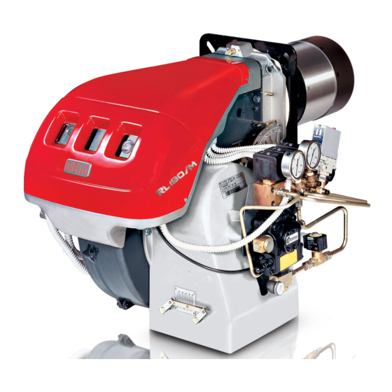
Riello RL 190/M Installation, Use And Maintenance Instructions
Light oil burner
Hide thumbs
Also See for RL 190/M:
- Installation, use and maintenance instructions (64 pages) ,
- Installation, use and maintenance instructions (36 pages) ,
- Installation, use and maintenance instructions (44 pages)
Table of Contents

Related Manuals for Riello RL 190/M


Summary of Contents for Riello RL 190/M
- Page 1 Installation, use and maintenance instructions Light oil burners Progressive two-stage or modulating operation CODE MODEL TYPE 20166488 RL 190/M 674 T1 20166490 RL 190/M 674 T1 20169231 RL 190/M 674 T1 20166451 (1) - 11/2019...
- Page 2 Translation of the original instructions...
-
Page 3: Table Of Contents
Contents Declarations....................................3 Information and general warnings............................4 Information about the instruction manual ........................4 2.1.1 Introduction.................................. 4 2.1.2 General dangers................................4 2.1.3 Other symbols ................................4 2.1.4 Delivery of the system and the instruction manual...................... 5 Guarantee and responsibility............................5 Safety and prevention................................ - Page 4 Contents 6.3.3 Intermediate outputs ..............................28 6.3.4 Servomotor ................................28 Pressure switch adjustment ............................29 6.4.1 Oil pressure switch..............................29 Operation sequence of the burner ..........................30 6.5.1 Burner start-up ................................30 6.5.2 Steady state operation ...............................30 6.5.3 Ignition failure................................30 6.5.4 Burner flame goes out during operation........................30 Final checks ................................30 Maintenance ....................................31 Notes on safety for the maintenance .........................31...
-
Page 5: Declarations
The quality is guaranteed by a quality and management system certified in accordance with ISO 9001:2015. Manufacturer's Declaration RIELLO S.p.A. declares that the following products comply with the NOx emission limits specified by German standard “1. BImSchV revision 26.01.2010”. Product... -
Page 6: Information And General Warnings
Information and general warnings Information and general warnings Information about the instruction manual 2.1.1 Introduction WARNING: MOVING PARTS The instruction manual supplied with the burner: This symbol indicates that you must keep limbs is an integral and essential part of the product and must not away from moving mechanical parts;... -
Page 7: Delivery Of The System And The Instruction Manual
Information and general warnings 2.1.4 Delivery of the system and the instruction The system supplier must carefully inform the user about: – the use of the system; manual – any further tests that may be required before activating the When the system is delivered, it is important that: system;... -
Page 8: Safety And Prevention
Safety and prevention Safety and prevention Introduction The burners have been designed and built in compliance with frequency of the electrical power supply, the minimum and current regulations and directives, applying the known technical maximum deliveries for which the burner has been regulated, the safety rules and envisaging all the potential danger situations. -
Page 9: Technical Description Of The Burner
Voltage of auxiliaries: 230/50/60 230V / 50-60Hz 110/50/60 110V / 50-60Hz 3/230/50 230/50 BASIC DESIGNATION EXTENDED DESIGNATION Models available Designation Electrical power supply Start-up Code RL 190/M 3/230/50 Direct 20166488 RL 190/M 3/400/50 Direct 20166490 RL 190/M 3/400/50 Direct 20169231 20166451... -
Page 10: Technical Data
Technical description of the burner Technical data Model RL 190/M Type 674 T1 Output 1423 - 2431 Max. Mcal/h 1224 - 2091 kg/h 120 - 205 534 - 1423 Min. Mcal/h 459 - 1224 kg/h 45 - 120 Fuel Light oil kWh/kg 11.86... -
Page 11: Overall Dimensions
Bear in mind that inspection of the combustion head requires the burner to be opened and the rear part drawn back on the slide bars. D1217 Fig. 1 RL 190/M 370 - 528 1166-1285 Tab. D Standard equipment The burner is supplied complete with: Flexible hoses . -
Page 12: Firing Rates
Technical description of the burner Firing rates The burner may have to operate at a higher altitude and/or with During operation, burner output varies between: combustion air at a higher temperature. a MINIMUM OUTPUT: area A; Both air heating and increased altitude cause air volume ... -
Page 13: Test Boiler
The firing rates were obtained in special test boilers, according to EN 267 standard. D688 Fig. 3 Commercial boilers Burners RL 190/M have been designed only for combustion chambers with minimum dimensions in compliance with standard EN 304, with flue gases coming out from the bottom, for example ATTENTION three flue passes (not flue gas inversion boilers), accessible through the door. -
Page 14: Burner Description
Technical description of the burner 4.10 Burner description Ignition electrodes Combustion head Screw for combustion head adjustment Screw for fixing fan to flange Oil pressure switch Nozzle return pressure gauge Nozzle delivery pressure gauge Pump Nozzle holder 10 Air dampers 11 Safety solenoid valves 12 Fan pressure test point 13 Boiler fixing flange... -
Page 15: Electrical Panel Description
Technical description of the burner 4.11 Electrical panel description 20169284 Fig. 6 Ignition transformer Power switch for: automatic - manual - off operation Button for: power increase - power reduction Motor contactor and thermal relay with reset button Terminal board for electric connection Cable grommets for external connections (to be carried out by the installer) Control box base... -
Page 16: 4.12 Control Box Rfgo-A23
Technical description of the burner 4.12 Control box RFGO-A23 Important notes To avoid accidents, material or environmental damage, observe the following instructions! The control box is a safety device! Avoid opening ATTENTION or modifying it, or forcing its operation. The Manufacturer cannot assume any responsibility for damage resulting from unauthorised work! ... -
Page 17: Servomotor (Sqn31
Technical description of the burner 4.13 Servomotor (SQN31...) Important notes To avoid accidents, material or environmental damage, observe the following instructions! Avoid opening, modifying forcing ATTENTION actuators. All interventions (assembly and installation operations, assistance, etc.) must be carried out by qualified personnel. ... -
Page 18: Installation
CAUTION The packaging elements (wooden cage or cardboard box, nails, clips, plastic bags, etc.) RIELLO S.p.A. I 37045 Legnago (VR) must not be abandoned as they are potential sources of danger and pollution; they should be... -
Page 19: Operating Position
Boiler plate Pierce the closing plate of the combustion chamber, as in Fig. 11. The position of the threaded holes can be marked using the thermal insulation screen supplied with the burner. RL 190/M 325-368 M 16 Tab. G D455 Fig. -
Page 20: Securing The Burner To The Boiler
Installation Securing the burner to the boiler Remove blast tube 9)(Fig. 12) from the burner 6)(Fig. 12): loosen the 4 screws 3) and remove the cover 1); Provide an adequate lifting system. remove screws 2) from the two slide bars 5); ... -
Page 21: Nozzle Installation
It is advisable to replace the nozzle once a year In order to guarantee that emissions do not vary, recommended during periodical maintenance. and/or alternative nozzles specified by Riello in the Instruction ATTENTION and warning booklet should be used. The use of nozzles other than those specified by 5.9.1... -
Page 22: Combustion Head Adjustment
RL 190/M, maximum light oil output = 150 kg/h The diagram (Fig. 18) indicates that, for an output of 150 kg/h, the combustion head of the burner RL 190/M has to be adjusted at D462 approximately 3 notches, as shown in Fig. 17. -
Page 23: Light Oil Supply
Installation 5.12 Light oil supply Explosion danger due to fuel leaks in the presence of a flammable source. Precautions: avoid knocking, attrition, sparks and heat. Make sure the fuel shut-off valve is closed before performing any operation on the burner. The fuel supply line must be installed by qualified personnel, in compliance with current standards and laws. -
Page 24: 5.12.1 Hydraulic Connections
Installation 5.12.1 Hydraulic connections 5.12.2 Hydraulic circuit diagram Make sure that the hoses to the pump supply and return line are installed correctly. CAUTION Double-pipe circuit The pumps are equipped with a by-pass that connects return line with suction line. They are installed on the burner with the by-pass closed by screw 6)(Fig. -
Page 25: Pump
Installation 5.13 Pump 5.13.1 Technical data The time required for this operation depends upon the diameter and length of the suction tubing. Pump If the pump fails to prime at first start-up and the burner locks out, Min. delivery rate at 20 bar pressure kg/h wait approx. -
Page 26: Electrical Connections
Installation 5.14 Electrical connections Notes on safety for the electrical wiring The electrical wiring must be carried out with the electrical supply disconnected. Electrical wiring must be made in accordance with the regulations currently in force in the country of destination and by qualified personnel. -
Page 27: Supply Cables And External Connections Passage
Installation 5.14.1 Supply cables and external connections passage All the cables to be connected to the burner terminal board 7)(Fig. 24) must be threaded through cable grommets. The use of the cable grommets and the pre-blanked holes can be done in different manners; for example: Pg 13.5 three-phase power supply Pg 11... -
Page 28: Start-Up, Calibration And Operation Of The Burner
Start-up, calibration and operation of the burner Start-up, calibration and operation of the burner Notes on safety for the first start-up The first start-up of the burner must be carried out Check the correct working of the adjustment, by qualified personnel, as indicated in this manual command and safety devices. -
Page 29: Min Output
Start-up, calibration and operation of the burner Pressure variator Air adjustment The fuel pressure on the nozzle delivery line is adjusted on the Progressively adjust the end profile of cam 2)(Fig. 31) by turning pressure variator unit and displayed on the pressure gauge the screws 5)(Fig. -
Page 30: Intermediate Outputs
Start-up, calibration and operation of the burner 6.3.3 Intermediate outputs If you want to check the output delivery of the nozzle, open the burner, connect a pipe to the nozzle, simulate the Setting minimum and maximum pressures automatically ignition and proceed with the weighing of the fuel at the determines pressure values and therefore intermediate outputs. -
Page 31: Pressure Switch Adjustment
Start-up, calibration and operation of the burner Pressure switch adjustment 6.4.1 Oil pressure switch The pressure switch 5)(Fig. 5 on page 12) is adjusted in the factory at 3 bar. If the light oil pressure reaches this value in the return duct, the pressure switch stops the burner. -
Page 32: Operation Sequence Of The Burner
Start-up, calibration and operation of the burner Operation sequence of the burner 6.5.1 Burner start-up 6.5.2 Steady state operation Burner without output regulator RWF Once the start-up cycle is completed, the servomotor command moves on to the TR remote control that controls the pressure or the temperature in the boiler, point B. -
Page 33: Maintenance
Maintenance Maintenance Notes on safety for the maintenance The periodic maintenance is essential for the good operation, Before carrying out any maintenance, cleaning or checking safety, yield and duration of the burner. operations: It allows you to reduce consumption and polluting emissions and to keep the product in a reliable state over time. -
Page 34: Safety Components
Maintenance Filters Flame presence check Check the following filter boxes: Check the level of the flame detection signal with the “Check mode” function from the flame control: the LEDs from 2 to 6 • on line 1) • in the pump 2) • at the nozzle 3), and clean or replace indicate the flame signal level, respectively “LED indicator and as required. -
Page 35: Opening The Burner
Maintenance Opening the burner Disconnect the electrical supply from the burner by means of the system main switch. DANGER Close the fuel shut-off valve. DANGER Wait for the components in contact with heat sources to cool down completely. To open the burner, proceed as follows: ... -
Page 36: Led Indicator And Special Function
LED indicator and special function LED indicator and special function Description of LED lamps It turns on when the fan motor is powered (T6) and blinks when RUN/CHECK switch is set to “CHECK” during damper movement phases, PTFI AND MTFI. S9740 It blinks when the air damper is moving towards the maximum opening position until the Damper... -
Page 37: Led Lamps: Burner Operating Status
LED indicator and special function LED lamps: burner operating status OPERATING STATUSES INDICATED BY LEDS DURING NORMAL OPERATION AND CHECK MODE Operation Damper Damper Modulation Ignition Flame Status LED ● = ON open closed Icon S9740 S9741 S9742 S9743 S9744 S9745 S9746 Power OFF/ON... -
Page 38: Problems - Causes - Remedies Signalled By Led Indicators
Problems - Causes - Remedies signalled by LED indicators Problems - Causes - Remedies signalled by LED indicators When an emergency stop occurs, the control device LEDs Thermal unit’s operation, maintenance and indicate the cause of the stop. troubleshooting interventions must be carried out The terminal T3 is not powered. - Page 39 Problems - Causes - Remedies signalled by LED indicators Error / RFGO LED lock-out codes No. Faults LED 1 LED 2 LED 3 LED 4 LED 5 LED 6 LED 7 Operation Open Closed Auto Ignition Flame Status LED ● = ON damper damper Icon...
- Page 40 Problems - Causes - Remedies signalled by LED indicators No. Faults LED 1 LED 2 LED 3 LED 4 LED 5 LED 6 LED 7 Off-specification mains voltage ● ● ● ● Off-specification mains voltage ● ● ● ● ● UV: Internal fault ●...
- Page 41 Problems - Causes - Remedies signalled by LED indicators No. Faults Cause Solution Combustion airflow switch fault in Open the circuit upon T13 start-up Check the wiring for the air pressure the rest position switch Inspect the system, check the gas UV: no flame at the end of the 2 No flame at the end of the 2 safety time...
- Page 42 Problems - Causes - Remedies signalled by LED indicators No. Faults Cause Solution Direct ignition valve feedback fault The system detected the presence of Check the wiring and make sure that the voltage on T18 at the wrong moment or earthing is appropriate.
-
Page 43: A Appendix - Accessories
0...2.5 bar Output probe 3010213 RWF55 20099657 Pressure 0...16 bar 4...20 mA 3010214 Soundproofing box kit Burner Type dB(A) Code RL 190/M C4/5 3010404 Spacer kit Burner Code RL 190/M 3000722 Extended head kit Burner Code RL 190/M 20058084 Potentiometer kit... -
Page 44: Appendix - Electrical Panel Layout
Appendix - Electrical panel layout Appendix - Electrical panel layout Index of layouts Reference indication Functional layout RFGO-A23 Functional layout RFGO-A23 Electrical wiring that is the responsibility of the installer Functional diagram RWF50... Reference indication / 1 . A 1 Sheet no. - Page 45 Appendix - Electrical panel layout 20166451...
- Page 46 Appendix - Electrical panel layout 20166451...
- Page 47 Appendix - Electrical panel layout 20166451...
- Page 48 Appendix - Electrical panel layout 20166451...
- Page 49 Appendix - Electrical panel layout Wiring layout key Control box RWF Output power regulator Probe with output under current Device with output under current for change of remote setpoint Pressure probe Pressure probe Remote setpoint potentiometer Thermocouple probe Probe Pt100, 2 wires Probe Pt100, 3 wires Probe Pt100, 3 wires BTEXT...
- Page 52 RIELLO S.p.A. I-37045 Legnago (VR) Tel.: +39.0442.630111 http:// www.riello.it http:// www.riello.com Subject to modifications...