Riello RL 190/M Installation, Use And Maintenance Instructions
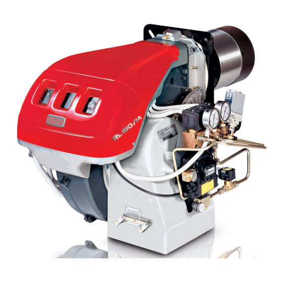
Light oil burner
Hide thumbs
Also See for RL 190/M:
- Installation, use and maintenance instructions (64 pages) ,
- Installation, use and maintenance instructions (52 pages) ,
- Installation, use and maintenance instructions (52 pages)

Related Manuals for Riello RL 190/M


Summary of Contents for Riello RL 190/M
- Page 1 Installation, use and maintenance instructions Light oil burner Low - high or modulating operation CODE MODEL 20050171 RL 190/M 20051197 (5) - 11/2014...
-
Page 3: Table Of Contents
Contents Information and general instructions ..............3 Information about the instruction manual . - Page 4 Contents 4.15 Motor connection at 575V ..............24 4.16 Reversible direction .
-
Page 5: Information And General Instructions
Information and general instructions Information and general instructions Information about the instruction manual 1.1.1 Introduction WARNING: MOVING PARTS The instruction manual supplied with the burner: This symbol indicates that you must keep limbs ➤ is an integral and essential part of the product and must not be away from moving mechanical parts;... -
Page 6: Delivery Of The System And The Instruction Manual
Information and general instructions 1.1.4 Delivery of the system and the instruction ➤ The system supplier must carefully inform the user about: – the use of the system; manual – any further tests that may be required before activating the When the system is delivered, it is important that: system;... -
Page 7: Safety And Prevention
Safety and prevention Safety and prevention Introduction The burners have been designed and built in compliance with cur- the type and pressure of the fuel, the voltage and frequency of the rent regulations and directives, applying the known technical rules electrical power supply, the minimum and maximum deliveries for of safety and envisaging all the potential danger situations. -
Page 8: Technical Description Of The Burner
Technical description of the burner Technical description of the burner Technical data Model RL 190/M Output High MBtu/hr 5376 - 9184 38.4 - 65.6 Delivery MBtu/hr 1792 - 5376 12.8 - 38.4 Fuel #2 Fuel oil Operation Low-high or modulating... -
Page 9: Packaging - Weight - Approximate Measurements
Packaging - weight - Approximate measurements The burners are skid mounted. Outer dimensions of packaging are indicated in (Tab. D). The weight of the burner complete with packaging is indicated in (Tab. D). inch RL 190/M 16“ 64“ 8“ Tab. D Fig. 1 Burner dimensions The maximum dimensions of the burners are given in Fig. -
Page 10: Procedure To Refer Burner Operating Condition In High Altitude Plants
Technical description of the burner 3.6.1 Procedure to refer burner operating condition Rated capacity = 3000 MBtu/hr - Rated air pressure = 1.5” WC in high altitude plants Real altitude = 5000 ft - Real temperature = 108°F ∆ Find the CORRECTED BURNER CAPACITY for the plant’s alti- = 108°F - 68°F (reference temp.) = 40°F tude in chart 1 and the CORRECTED PRESSURE in chart 2. -
Page 11: Minimum Furnace Dimensions
Technical description of the burner CORRECTED BURNER AIR PRESSURE ACCORDING TO ALTITUDE Altitude m a.s.l. 1220 1525 1830 2135 2440 Rated Pressure ft a.s.l 1000 2000 3000 4000 5000 6000 7000 8000 0.50 0.49 0.50 0.51 0.53 0.55 0.57 0.59 0.62 0.64 0.67... -
Page 12: Commercial Boilers
Technical description of the burner Commercial boilers The burner is suitable for operation on either flame-inversion boil- ers* or boilers with combustion chambers featuring flow from the base (three flue passes) on which the best results are obtained in 10” max terms of low NOx emissions. -
Page 13: Standard Equipment
Technical description of the burner Ignition electrodes 32 RWF 40 modulator (with analog output 4-20 mA) (Available) Combustion head 33 "POWER ON" signal Screw for combustion head adjustment 34 "CALL FOR HEAT" signal Screw for fixing fan to flange 35 "ALARM" signal Pressure gauge for pressure on nozzle return 36 "IGNITION ON"... -
Page 14: Honeywell Control Box
Technical description of the burner 3.11 Honeywell control box Wiring subbase Run/test switch Relay module Configuration jumpers Purge timer Sequence status led panel Reset button Captive mounting screw Keyboard display module Flame amplifier Fig. 7 S8158 APPLICATION SPECIFICATIONS The Honeywell RM7840 ... Relay Modules are microprocessor- Electrical ratings based integrated burner controls for automatically fired gas, oil, or Voltage and Frequency:... -
Page 15: Rm7840
Technical description of the burner 3.11.1 RM7840 ... sequence diagram S8160 Fig. 8 For further and specific information (setting and service work, etc.), please refer to the specific instruction of the control box. Warning notes To avoid injury to persons, damage to property or the environment, the following warning notes must be observed! WARNING... -
Page 16: Actuator
Technical description of the burner 3.12 Actuator Warning notes To avoid injury to persons, damage to property or the environment, the following warning notes should be observed! WARNING Do not open, interfere with or modify the actua- tors! ➤ All activities (mounting, installation and service work, etc.) must be performed by qualified staff. -
Page 17: Installation
Installation Installation Notes on safety for the installation After carefully cleaning all around the area where the burner will be The installation of the burner must be carried out by installed, and arranging the correct lighting of the environment, pro- qualified personnel, as indicated in this manual and ceed with the installation operations. -
Page 18: Burner Raising
The range of lengths available, L (inch), is as follows: Model RL 190/M “ Tab. I For boilers with front flue passes 12) or flame inversion chambers, protective insulation 10) must be inserted between the boiler re- fractory 11) and the blast tube 9). -
Page 19: Securing The Burner To The Boiler
In order to guarantee that emissions do not vary, recommended blast tube. and/or alternative nozzles specified by Riello in the Instruction and At this point install the nozzle with the box wrench 1)(Fig. 14), fitting warning booklet should be used. -
Page 20: Adjusting The Nozzle Flow Rate
Installation Make sure that the electrodes are positioned as shown in Fig. 15. 4.9.3 Adjusting the nozzle flow rate The nozzle flow rate varies according to the fuel pressure on the nozzle return. Diagram (Fig. 19) indicates this relationship for type A4 return flow nozzles with pump delivery pressure of 290 PSI. -
Page 21: Combustion Head Setting
5)(Fig. 20). Example RL 190/M, maximum light oil delivery = 48 GPH Diagram (Fig. 21) indicates that for a delivery of 48 GPH the RL 190/M Model requires the combustion head to be set to approx. -
Page 22: Light Oil Supply
Installation 4.11 Light oil supply Explosion danger due to fuel leaks in the presence of a flammable source. Precautions: avoid knocking, attrition, sparks and heat. Make sure the fuel interception tap is closed before performing any operation on the burner. The fuel supply line must be installed by qualified personnel, in compliance with current standards and laws. -
Page 23: Hydraulic Connections
Installation 4.11.3 Hydraulic connections The pumps are equipped with a by-pass that separates return line with suction line (Fig. 24). The pumps are installed on the burner with the by-pass closed by screw 6)(Fig. 44, page 30). It is therefore necessary to connect both hoses to the pump. The pump seal will be damaged immediately if it is run with the return line closed and the by-pass screw inserted. -
Page 24: Electrical Wiring
Installation 4.12 Electrical wiring Notes on safety for the electrical wiring ➤ The electrical wiring must be carried out with the electrical supply disconnected. ➤ Electrical wiring must be carried out by qualified personnel and in compliance with the regulations currently in force in the country of destination. -
Page 25: Thermal Relay Calibration
Installation 4.13 Thermal relay calibration Depending on the burner type, there are two different thermal re- 4.13.2 Electronic thermal relay lays: ➤ To reset, in the case of an intervention of the thermal relay, – Electro-mechanical termal relay (used for single phase motors) press the button “RESET”... -
Page 26: Motor Connection At 208-230 Or 460V
Installation 4.14 Motor connection at 208-230 or 460V WARNING: the motors, manufactured for 208-230/460 IE2/Epact voltage, have a different connection than IE1 motors, no more star/delta but star/double star. Please, pay attention to the indications in case of modification of voltage, maintenance, or substitution. IE2/Epact S8380 S8379... -
Page 27: Start-Up, Calibration And Operation Of The Burner
Start-up, calibration and operation of the burner Start-up, calibration and operation of the burner Notes on safety for the first start-up The first start-up of the burner must be carried out Check the correct working of the adjustment, com- by qualified personnel, as indicated in this manual mand and safety devices. -
Page 28: Intermediate Output
Start-up, calibration and operation of the burner 5.3.3 Intermediate output Check the various setting levels with a combustion analysis. Turn the selector 29)(Fig. 6, page 10) in various intermediate lev- Make a progressive setting of the profile, without els between maximum and minimum and set the variable profile sharp changes. -
Page 29: Cams And Trim Potentiometers Functions
Start-up, calibration and operation of the burner 5.4.1 Cams and trim potentiometers functions Cam 1: 130° Limits rotation towards maximum for oil Cam 2: 0° Limits rotation towards minimum, air damper closed on stand by Cam 3: 20° Limits OIL ignition position and minimum position Cams 4 - 5 - 6 - 7 - 8: not used D10732 Disconnect the control power supply and the main... -
Page 30: Flame Signal Measurement
Start-up, calibration and operation of the burner 5.5.4 Flame signal measurement amplifier (if the control has one). ➤ If you still cannot obtain a proper flame signal, replace flame Flame signal can be measured at the Flame Signal Test Jacks, see detector or UV radiation sensing tube. -
Page 31: Final Calibration Of The Pressure Switches
Start-up, calibration and operation of the burner Final calibration of the pressure switches 5.6.1 Air pressure switch Adjust the air pressure switch after having performed all other burn- er adjustments with the air pressure switch set to the start of the scale (Fig. -
Page 32: Burner Starting
Start-up, calibration and operation of the burner Burner starting ➤ Operating control closes, the motor starts. 5.7.2 Firing failure The pump 3) (Fig. 44) draws the fuel from the tank through the ➤ If the burner does not fire, it goes into lock-out within 3 sec. of piping 1) and pumps it under pressure for delivery. -
Page 33: Maintenance
Maintenance Maintenance Notes on safety for the maintenance The periodic maintenance is essential for the good operation, safe- ty, yield and duration of the burner. Disconnect the electrical supply from the burner by It allows you to reduce consumption and polluting emissions and to means of the main system switch. - Page 34 Maintenance UV scanner ➤ Be extremely careful while troubleshooting the detector; line voltage is present on some of the terminals when power is on. WARNING ➤ Open the master switch to disconnect power before removing or installing the detector. Periodic maintenance and cleaning ➤...
-
Page 35: Opening The Burner
Maintenance Filters Check the following filter boxes on line 1) and at nozzle 2) and clean or replace as required. If rust or other impurities are observed inside the pump, use a separate pump to suck out any water and other impurities that may have deposited on the bottom of the tank. -
Page 36: A Appendix - Spare Parts
Appendix - Spare parts Appendix - Spare parts 20051197... - Page 37 Appendix - Spare parts CODE DESCRIPTION BURNER SERIAL NUMBER 3013760 END CONE ≤ 02413xxxxxx 3013684 AIR DAMPER ASSEMBLY ≥ 02423xxxxxx 20073610 AIR DAMPER ASSEMBLY 3013683 GRID 3007079 SEAL 3003006 CONNECTOR 3012455 CONNECTOR 3009081 CONNECTOR 3013029 TUBE 3003055 CONNECTOR 3006184 SCREW 3007164 SEAL 3007077...
- Page 38 Appendix - Spare parts CODE DESCRIPTION BURNER SERIAL NUMBER 3013868 TUBE 3013867 TUBE 3003005 CONNECTOR 3012646 TIE ROD 3009080 CONNECTOR 3012601 LEVER 3012472 BEARING 3012356 FLAT SPRING 3012358 CAM ASSEMBLY 3013028 SHAFT 3003287 COIL 3007150 O RING 3003204 SEAL 3003200 3012474 MODULATOR 3006723...
-
Page 39: B Appendix - Accessories
Appendix - Accessories Appendix - Accessories • Flame inversion boiler kit Burner Code RL 190/M 3010241 The installer is responsible for the supply and instal- lation of any required safety device(s) not indicated in this manual. WARNING 20051197... -
Page 40: Appendix - Burner Start Up Report
Appendix - Burner start up report Appendix - Burner start up report Model number: Serial number: Project name: Start-up date: Installing contractor: Phone number: OIL OPERATION : Low Fire Oil supply pressure: High Fire : Low Fire Oil suction pressure: High Fire Control Power Supply: CO: Low Fire... - Page 44 RIELLO S.p.A. I-37045 Legnago (VR) Tel.: +39.0442.630111 http:// www.riello.com RIELLO BURNERS NORTH AMERICA 1-800-4-RIELLO 35 Pond Park Road 2165 Meadowpine Blvd Hingham, Massachusetts, 1-800-474-3556 Mississauga, Ontario U.S.A. 02043 Canada L5N 6H6 http://www.riello.ca Subject to modifications...