Table of Contents
Advertisement
Quick Links
Packing List
Packing List
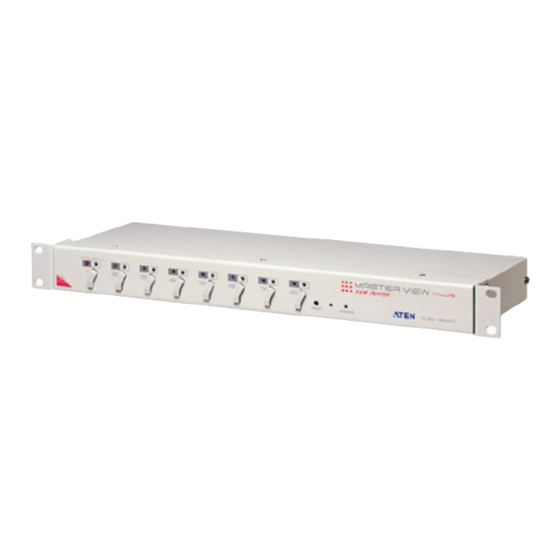
The complete Master View CS-138A package consists of:
One Master View CS-138A KVM Switch
One Power Adapter
One User Manual
Check to make sure that the unit was not damaged in shipping. If you
encounter a problem, contact your dealer.
Please read this manual thoroughly, and follow the installation and operation
procedures carefully to prevent any damage to the Master View CS-138A
unit, and/or any of the devices connected to it.
All brand names and trademarks are the registered property of their respective owners.
Copyright 2000 ATEN International Co., Ltd.
Manual Part No. PAPE-0115-400
Printed in Taiwan 03/2000
Advertisement
Table of Contents

Related Manuals for ATEN Master View CS-138A


Summary of Contents for ATEN Master View CS-138A
- Page 1 Please read this manual thoroughly, and follow the installation and operation procedures carefully to prevent any damage to the Master View CS-138A unit, and/or any of the devices connected to it. Copyright 2000 ATEN International Co., Ltd.
-
Page 2: Table Of Contents
Table of Contents Table of Contents Overview ...1 Features ...2 Hardware Requirements ...3 Console...3 PC ...3 Cables...4 Introduction...5 Front View...5 Rear View ...6 Installation ...7 Single Stage Installation...7 Two Stage Installation ...8 Three Stage Installation ...9 Operation ...11 Hot Plugging ...11 Powering Off and Restarting ...12 Port Selection ...12 Port ID Numbering...14... -
Page 3: Overview
A Master View CS-138A unit can control up to 8 PCs. Units can be cascaded to three levels, which means that up to 73 Master View units can control up to 512 PCs - all from a single console. -
Page 4: Features
Features Features Cascadable To Three Levels - Control Up to 512 PCs From a Single Console No Software Required - PC Selection via Front Panel Switches, Hot Keys, or OSD (On Screen Display) Quick View Scan Feature for Monitoring Selected PCs PS/2 and Serial Mouse Emulation Provided For System Bootup Console's PS/2 Mouse Controls All Connected PCs - Even Those With Serial Mice... -
Page 5: Hardware Requirements
Hardware Requirements Hardware Requirements Console A VGA, SVGA, or Multisync monitor capable of the highest resolution that you will be using on any PC in the installation A PS/2 Style Mouse A PS/2 Style Keyboard The following equipment must be installed on each PC that is to be connected to the system: A VGA, SVGA or Multisync card. -
Page 6: Cables
Cables Although it is possible to use standard extender cables to connect the PCs to the Master View CS-138A, for optimum signal integrity and to simplify the layout, we strongly recommend that you use the following high quality CS Custom... -
Page 7: Introduction
Pressing Buttons 7 and 8 simultaneously starts Auto Scan Mode. 3. CS-138A Reset To reset the CS-138A, use a thin object (such as the end of a paper clip, or a ballpoint pen), to press this recessed switch in to initiate a warm reset. If the switch is kept in for longer than three seconds, a cold reset takes place. -
Page 8: Rear View
Rear View: 1. Power Jack The power adapter plugs in here. The unit is designed to be non-powered (no external power required), in which case it takes the necessary power for its operation from the computers it connects to. Generally speaking, the only time that external power is required is when you daisy chain it, or if operation becomes erratic because the unit isn't obtaining enough power from the computer connections. -
Page 9: Installation
Installation Installation Before you Begin Make sure that power to all the devices you will be connecting up have been turned off. To prevent damage to your installation due to ground potential difference, make sure that all devices on the installation are properly grounded. -
Page 10: Two Stage Installation
Two Stage Installation To provide control for more than just eight PCs, additional Master View CS- 138A units can be cascaded from the CPU ports of the First Stage unit. The cascaded Master Views that connect back to the First Stage unit are considered Second Stage units. -
Page 11: Three Stage Installation
Three Stage Installation The procedures for setting up a three stage installation are essentially the same as for a two stage installation. With a three stage setup, however, as many as 512 PCs can be controlled in a complete installation. A table showing the relation between the number of PCs and the number of Master View units needed to control them is provided in the Appendix. - Page 12 want to control to any available CPU Port on the Third Stage unit, as shown in the diagram below. 4. Plug the power adapter into an AC source; plug the power adapter cable into the Master View's Power Jack. 5. Repeat steps 2 - 4 for any other Third Stage units you wish to connect. 6.
-
Page 13: Operation
Operation Hot Plugging The Master View CS-138A supports hot plugging - which means that components can be removed and added back into the installation by unplugging their cables from the CPU ports without the need to shut the unit down. There... -
Page 14: Powering Off And Restarting
2) If the unit is operating under external power, unplug the power adapter cable. 2. Wait 10 seconds, then plug the Master View CS-138A stations back in, starting with the last station in the chain and working back to the station you originally shut down. - Page 15 PC you want to access. 2) Simultaneously pressing Port Selection buttons 7 and 8 on the First Stage unit initiates the CS-138A’s Quick View Scan feature, in which all the ports currently selected for Quick View scanning with the OSD function are cycled through. The length of time spent on each port is determined with the OSD’s F6 SET function...
-
Page 16: Port Id Numbering
Port ID Numbering Port ID Numbering Since each CPU Port on a Master View installation is assigned a unique Port ID, you can directly access any computer on any level of the installation by specifying the Port ID that the computer is connected to using the Hotkey port selection method, or from the OSD Main Menu. -
Page 17: Port Key In Examples
Port Key In Examples: 1. To access a computer attached to Port 3 of a Single Stage installation, key in 3 for the Port ID, as follows: [Ctrl+Alt+Shift] 3 [Enter] 2. To access a computer attached to Port 3 of a Second Stage unit that is cascaded down from Port 2 of the First Stage unit, key in 23 for the Port ID, as follows: [Ctrl+Alt+Shift] 2 3 [Enter]... -
Page 18: Osd Operation
OSD Operation OSD Operation Hotkey Navigation Hotkey navigation can be used under OSD mode. To hotkey select a port from the OSD, do the following: 1. Activate the OSD by pressing the Ctrl key twice ([Ctrl] [Ctrl]). Note: 1. If the OSD is already active, when you are at the Main Menu you can key in the hotkey without first having to press [Ctrl] [Ctrl]. -
Page 19: Osd Overview
- especially in large, daisy chained installations where a great number of PCs are connected to a several Master View CS-138A units, and it is difficult to keep track of which port a particular PC is attached All operations start from the OSD Main Menu. -
Page 20: Osd Navigation
OSD Navigation [Esc] cancels the current selection, or dismisses the current menu and moves back to the menu one level above. If you are at the highest menu level, it deactivates OSD. Use the Up and Down Arrow Keys to move up or down through the list one line at a time Use [Pg Up] and [Pg Dn] to move up or down through the list one screen at a time... -
Page 21: The Function Keys
The Function Keys: Pressing a Function Key brings up a related submenu that is used to configure and control the OSD to make it convenient for you to work with. For example, you can: rapidly switch to any port; scan selected ports only; limit the list you wish to view;... - Page 22 w w F3 List: This function brings up a submenu that lets you broaden or narrow the scope of which ports the OSD lists. The choices and their meanings are given in the table, below: Choice QView Powered On + QView QView + Name Name Powered On...
- Page 23 F4 QV You can broaden or narrow the number of ports that get automatically scanned by selecting only the ones you want with the QV (Quick View Scan) function. [F4] is a toggle that selects or deselects the currently highlighted port for the Quick View Scanning function (see F2, above).
- Page 24 w w F6 Set When you press [F6] an OSD configuration submenu. To change a setting, move the highlight bar to the choice you want, then press [Enter]. On the submenu that appears next, move the highlight bar to the choice you want and press [Enter].
-
Page 25: Factory Default Settings
Setting Restore Default Values Clears all settings from memory, and returns the unit to the factory defaults. You are asked to confirm before the procedure goes on. Key in Y, then press [Enter] to confirm. While the settings are being cleared, a message appears on the display to indicate so. -
Page 26: Osd Security
OSD Security In order to prevent unauthorized access to the computers, the OSD provides a password security feature. If a password has been set, the OSD will request that the user specify it before allowing entry. Password: To set a password: 1. -
Page 27: Appendix
Appendix Appendix Master View - Computer Connection Table The following table indicates the relationship between the number of Master View Units and the number of PCs that they control: 8-15 15 - 22 22 - 29 29 - 36 36 - 43 43 - 50 50 - 57 57 - 64... -
Page 28: Mounting And Stacking
Mounting and Stacking For convenience in large installations, the unit is supplied with the necessary hardware for it to be rack mounted in a 19” (1U) system rack, or stacked. For Rack Mounting: 1. Screw the mounting brackets into the sides of the unit, as shown in the diagram below 2. -
Page 29: Troubleshooting
Troubleshooting Symptom Possible Cause Erratic Behavior Unit not receiving enough power under self-powered operation. Pressing the Hot The connection from the Keys gets no selected port to the target response. PC has been broken, or the PC is turned OFF. Improper keyboard reset. -
Page 30: Specifications
Specifications Function PC Connections Direct Port Selection LEDs Power On Line Port Selected Port Connectors Keyboard Mouse Video Scan Interval (OSD Select) Power Consumption Operating Temperature Storage Temperature Humidity Housing Weight Dimensions (L x W x H) Specification 512 (via Daisy Chain) Front Panel Switches Hot Keys On Screen Display... -
Page 31: Federal Communications Commission Statement
Federal Communications Commission Statement This device complies with Part 15 of the FCC Rules. Operation is subject to the following two conditions: (1) this device may not cause harmful interference, and (2) this device must accept any interference received, including interference that may cause undesired operation.