Sony DCR-TRV320 Service Manual
Hide thumbs
Also See for DCR-TRV320:
- Operating instructions manual (132 pages) ,
- Limited warranty (1 page) ,
- Operating instructions manual (132 pages)
Table of Contents
Advertisement
SERVICE MANUAL
Ver 1.4 2004. 09
TM
B700 MECHANISM
NTSC MODEL : DCR-TRV320/TRV320P/TRV520/TRV520P/TRV525/TRV720
PAL MODEL
: DCR-TRV320E/TRV420E/TRV520E/TRV620E/TRV720E
When the machine needs to be repaired,
please refer to page 9 to discriminate
the type of LCD.
Video camera
recorder
System
Video recording system
2 rotary heads
Helical scaning system
Audio recording system
Rotary heads, PCM system
Quantization: 12 bits (Fs 32 kHz,
stereo 1, stereo 2), 16 bits
(Fs 48 kHz, stereo)
Video signal
DCR-TRV320/TRV320P/TRV520/
TRV520P/TRV525/TRV720 :
NTSC color, EIA standards
DCR-TRV320E/TRV420E/TRV520E/
TRV620E/TRV720E :
PAL colour, CCIR standards
Recommended cassette
Hi8/Digital8 video cassette
Recording/Playback time (using
120 min. Hi8 video cassette)
SP mode: 1 hour
LP mode: 1 hour and 30 minutes
Fastforward/rewind time (using
120 min. Hi8 video cassette)
Approx. 5 min.
DCR-TRV320/TRV320E/TRV320P/TRV420E/
TRV520/TRV520E/TRV520P/TRV525/
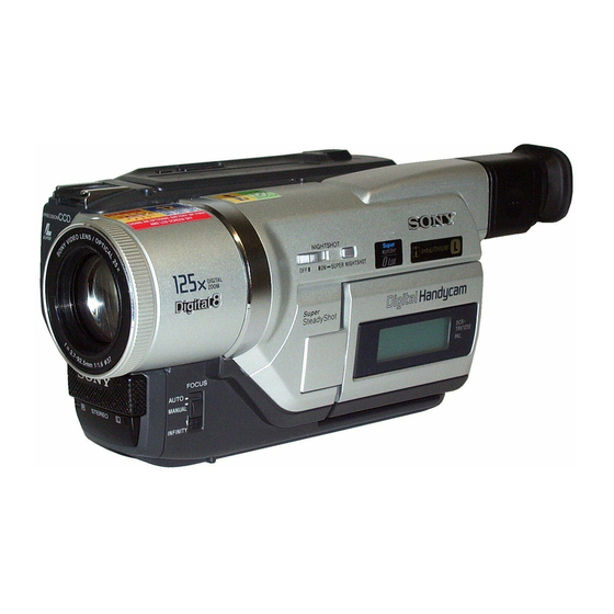
Photo: DCR-TRV320
SPECIFICATIONS
Viewfinder
Electric Viewfinder (monochrome)
Image device
1/4 type CCD (Change Coupled
Device)
DCR-TRV320/TRV320P/TRV520/
TRV520P/TRV525/TRV720 :
Approx. 460,000 pixels
(Effective: Approx. 290,000 pixels)
DCR-TRV320E/TRV420E/TRV520E/
TRV620E/TRV720E :
Approx. 800,000 pixels
(Effective: Approx. 400,000 pixels)
Lens
Combined power zoom lens
Filter diameter 37 mm (1 1/2 in.)
25× (Optical)
DCR-TRV320/TRV320E: E, AUS, HK,
CN/TRV320P/TRV420E: CN/TRV520/
TRV520E: E, AUS, HK, CN, JE/
TRV520P/TRV525/TRV720/TRV720E:
E, HK, CN :
450× (Digital)
DCR-TRV320E: AEP, UK, EE, NE, RU/
TRV520E: AEP/TRV620E/TRV720E:
AEP :
100× (Digital)
DCR-TRV420E: AEP :
125× (Digital)
DIGITAL VIDEO CASSETTE RECORDER
TRV620E/TRV720/TRV720E
DCR-TRV320E/TRV420E/TRV520E/TRV620E/TRV720E
For MECHANISM ADJUSTMENT, refer to
the "8mm Video MECHANICAL
ADJUSTMENT MANUAL
Focal length
3.7 - 92.5 mm (5/32 - 3 3/4 in.)
When converted to a 35 mm still camera
48 - 1200 mm (1 15/16 - 47 1/4 in.)
Colour temperature
Auto
Minimum illumination
DCR-TRV320/TRV320P/TRV520/
TRV520P/TRV525/TRV720 :
1 lux (F 1.6)
DCR-TRV320E/TRV420E/TRV520E/
TRV620E/TRV720E :
3 lux (F 1.6)
0 lux (in the NightShot mode)*
* Objects unable to be seen due to the
dark can be shot with infrared
lighting.
Input/output
connectors
DCR-TRV320/TRV320P/TRV520/
TRV520P/TRV525/TRV720 :
S video input/output
4-pin mini DIN
Luminance signal: 1 Vp-p,
75 ohms, unbalanced
Chrominance signal: 0.286 Vp-p,
75 ohms, unbalanced
RMT-814
US Model
DCR-TRV320/TRV520/TRV525/TRV720
Canadian Model
DCR-TRV320/TRV525/TRV720
AEP Model
UK Model
DCR-TRV320E/TRV620E
East European Model
North European Model
Russian Model
DCR-TRV320E
E Model
DCR-TRV320/TRV320E/TRV320P/
TRV520/TRV520E/TRV520P/TRV720/TRV720E
Hong Kong Model
DCR-TRV320/TRV320E/
TRV520/TRV520E/TRV720E
Korea Model
DCR-TRV320/TRV520/TRV720
Argentina Model
DCR-TRV520P
Australian Model
DCR-TRV320E/TRV520E
Chinese Model
DCR-TRV320E/TRV420E/TRV520E/TRV720E
Tourist Model
DCR-TRV520/TRV520E
" (9-973-801-11).
Audio/Video input/output
AV MINIJACK, 1 Vp-p, 75 ohms,
unbalanced, sync negative
327 mV, (at output impedance more than
47 kilohms)
Output impedance with less than 2.2
kilohms/Stereo minijack (ø 3.5 mm)
Input impedance more than 47 kilohms
DCR-TRV320E: E, AUS, HK, CN/
TRV420E: CN/TRV520E: E, AUS, HK,
CN, JE/TRV620E/TRV720E :
S video input/output
4-pin mini DIN
Luminance signal: 1 Vp-p,
75 ohms, unbalanced
Chrominance signal: 0.3 Vp-p,
75 ohms, unbalanced
Audio/Video output
AV MINIJACK, 1 Vp-p, 75 ohms,
unbalanced, sync negative
327 mV, (at output impedance more than
47 kilohms)
Output impedance with less than 2.2
kilohms/Stereo minijack (ø 3.5 mm)
DCR-TRV320E: AEP, UK, EE, NE, RU/
TRV420E: AEP/TRV520E: AEP :
– Continued on next page –
Advertisement
Chapters
Table of Contents

Related Manuals for Sony DCR-TRV320


Summary of Contents for Sony DCR-TRV320
- Page 1 Australian Model DCR-TRV320E/TRV520E Chinese Model B700 MECHANISM DCR-TRV320E/TRV420E/TRV520E/TRV720E Photo: DCR-TRV320 Tourist Model DCR-TRV520/TRV520E NTSC MODEL : DCR-TRV320/TRV320P/TRV520/TRV520P/TRV525/TRV720 For MECHANISM ADJUSTMENT, refer to PAL MODEL : DCR-TRV320E/TRV420E/TRV520E/TRV620E/TRV720E the “8mm Video MECHANICAL ADJUSTMENT MANUAL ” (9-973-801-11). When the machine needs to be repaired, please refer to page 9 to discriminate the type of LCD.
- Page 2 47 kilohms) excluding the battery pack, lithium 3.5 W DCR-TRV420E: AEP : Output impedance with less than 2.2 battery, cassette and shoulder strap DCR-TRV320/TRV320E: E, AUS, HK, NP-F550: 10.8 Wh kilohms/Stereo minijack (ø 3.5 mm) DCR-TRV320/TRV320E/TRV320P/ CN/TRV320P : Dimensions (approx.)
- Page 3 SONY PARTS WHOSE PART NUMBERS APPEAR AS DE FONCTIONNEMENT. NE REMPLACER CES COM- SHOWN IN THIS MANUAL OR IN SUPPLEMENTS PUB- POSANTS QUE PAR DES PIÈCES SONY DONT LES LISHED BY SONY. NUMÉROS SONT DONNÉS DANS CE MANUEL OU DANS LES SUPPLÉMENTS PUBLIÉS PAR SONY.
- Page 4 – 4 –...
- Page 5 TABLE OF CONTENTS Section Title Page Section Title Page SERVICE NOTE Copying the Image Recorded on “Memory Stick” to Tapes ............1-28 Enlarging Recorded Still Images on “Memory Stick”s Power Supply During Repairs ........8 – Memory PB ZOOM ............1-29 To Take Out a Cassette Playing Back Images in a Continuous Loop When Not Eject (Force Eject) ........
- Page 6 Section Title Page Section Title Page VC-235 (LENS MOTOR DRIVE) 1-1. Preparations Before Adjustment Schematic Diagram ............ 4-19 (Camera Section) ..........5-4 VC-235 (VIDEO IN/OUT) Schematic Diagram ..4-21 1-1-1. List of Service Tools ..........5-4 VC-235 (BASE BAND INPUT) 1-1-2.
- Page 7 Section Title Page Section Title Page 5-2. MECHANISM SECTION ADJUSTMENT ....5-38 4-3. Service Mode ............5-62 2-1. Hi8/Standard 8 mm Mode ........5-38 1. Setting the Test Mode ........... 5-62 2-1-1. How to Enter Playback Mode Without Cassette ... 5-38 2.
- Page 8 SERVICE NOTE POWER SUPPLY DURING REPAIRS Battery switch In this unit, about 10 seconds after power is supplied (8.4 V) to the battery terminal using the service power cord (J-6082-223-A), the power is shut off so that the unit cannot operate. This following two methods are available to prevent this.
- Page 9 (Be careful or some pieces of gilt may be left inside) LCD TYPE CHECK By measuring the resistor value between Pin 6 of CN5502 and DCR-TRV320/TRV320E/TRV320P Pin q; of CN5502 on PD-117/118 board, the type of LCD can be discriminated. Volt ohm meter...
- Page 10 SELF-DIAGNOSIS FUNCTION Self-diagnosis Display Self-diagnosis Function When problems occur while the unit is operating, the counter of When problems occur while the unit is operating, the self-diagno- sis function starts working, and displays on the viewfinder or Dis- the viewfinder or Display window shows a 4-digit display consist- play window what to do.
- Page 11 Self-diagnosis Code Table Self-diagnosis Code Block Detailed Symptom/State Correction Function Code Condensation. Remove the cassette, and insert it again after one hour. Video head is dirty. Clean with the optional cleaning cassette. Non-standard battery is used. Use the InfoLITHIUM battery. LOAD direction.
- Page 12 Self-diagnosis Code Block Detailed Symptom/State Correction Function Code Inspect the lens block focus reset sensor (Pin 9 of CN1551 of VC-235 board) when focusing is performed when the control dial Difficult to adjust focus is rotated in the focus manual mode and the focus motor drive circuit (Cannot initialize focus) (IC1553 of VC-235 board) when the focusing is not performed.
- Page 13 Проверка прилагаемых Welcome! accessories Добро пожаловать! принадлежностей Congratulations on your purchase of this Sony Make sure that the following accessories are Digital Handycam camcorder. With your Digital supplied with your camcorder. Handycam, you can capture life’s precious moments with superior picture and sound quality.
- Page 14 — Подготовка к эксплуатации — Использование данного Использование — Getting started — Using this manual руководства Using this manual данного руководства Note on TV colour systems Примечание по системам The instructions in this manual are for the three цветного телевидения TV colour systems differ from country to models listed in the table below.
- Page 15 “InfoLITHIUM” battery. “InfoLITHIUM” battery using a normally charged battery. The battery life packs have the mark. will be shorter if you use your camcorder in a “InfoLITHIUM” is a trademark of Sony cold environment. Corporation. Supplied with DCR-TRV520E/TRV620E Supplied with DCR-TRV420E...
- Page 16 DC IN jack, even when the mains lead is not plugged into the mains. Using a car battery Use Sony DC Adaptor/Charger (not supplied). Использование автомобильного аккумулятора — Recording – Basics —...
- Page 17 Recording a picture Запись изображения Recording a picture Запись изображения Notes Примечания Adjusting the LCD screen Регулировка экрана ЖКД •Fasten the grip strap firmly. To adjust the brightness of the LCD screen, press •Do not touch the built-in microphone during recording.
- Page 18 Recording a picture Запись изображения Recording a picture Запись изображения Indicators displayed in the Индикаторы, отображаемые в Shooting backlit subjects Съемка объектов с задней recording mode режиме записи – BACK LIGHT подсветкой – BACKLIGHT The indicators are not recorded on tape. When you shoot a subject with the light source behind the subject or a subject with a light background, use the backlight function.
- Page 19 Checking the recording Проверка записи Recording a picture Запись изображения – END SEARCH / EDITSEARCH / – END SEARCH / EDITSEARCH / Rec Review Просмотр записи Self-timer recording Запись по таймеру самозапуска You can use these buttons to check the recorded Recording with the self-timer starts in 10 seconds picture or shoot so that the transition between automatically.
- Page 20 Playing back a tape Воспроизведение ленты Playing back a tape Воспроизведение ленты Using the data code function Использование функции кода даты When monitoring on the LCD screen Во время контроля на экране ЖКД Your camcorder automatically records not only You can turn the LCD panel over and move it images on the tape but also the recording data back to the camcorder body with the LCD screen (date/time or various settings when recorded)
- Page 21 При включенном лазерном суперканале S.LASER LINK button is lit) передачи сигналов (при этом Your camcorder consumes power. Press S.LASER высвечивается кнопка S.LASER LINK) LINK to turn off the super laser link function when it is not needed. is a trademark of Sony Corporation.
- Page 22 Recording a still image on a tape Запись неподвижного изображения Recording a still image on a tape Запись неподвижного изображения – Tape Photo recording на ленту – Фотосъемка на ленту – Tape Photo recording на ленту – Фотосъемка на ленту Notes Примечания...
- Page 23 Using the fader Использование function функции фейдера Using the fader function Использование функции фейдера You can fade the picture in or out to give your (1) When fading in [a] (1) При введении изображения [a] recording a professional appearance. In the standby mode, press FADER until the desired fader indicator flashes.
- Page 24 Использование Using special effects Использование специальных Using special effects специальных эффектов – Picture effect эффектов – Эффект изображения – Digital effect – Цифровой эффект (1) Press PICTURE EFFECT in CAMERA mode. The picture effect indicator appears. You can add special effects to recorded images (2) Turn the SEL/PUSH EXEC dial to select the using the various digital functions.
- Page 25 Using the PROGRAM Использование Использование функции AE function функции PROGRAM AE Using the PROGRAM AE function PROGRAM AE (1) Press PROGRAM AE in CAMERA or You can select PROGRAM AE (Auto Exposure) MEMORY mode. The PROGRAM AE mode to suit your specific shooting requirements. indicator appears.
- Page 26 Superimposing a title Наложение титра Focusing manually Фокусировка вручную You can select one of eight preset titles and two To focus precisely Для точной фокусировки custom titles (p. 61). You can also select the Adjust the zoom by first focusing at the “T” language, colour, size and position of titles.
- Page 27 Создание Ваших собственных Inserting a scene Вставка эпизода Making your own titles титров To change a title you have stored Для изменения сохраненного в You can insert a scene in the middle of a In step 3, select CUSTOM1 or CUSTOM2, памяти...
- Page 28 Enlarging recorded Увеличение записанных Enlarging recorded images Увеличение записанных images – PB ZOOM изображений – PB ZOOM – PB ZOOM изображений – PB ZOOM You can enlarge moving and still images Notes Примечания recorded on tapes. •PB ZOOM works only for tapes recorded in the Besides the operation described here, your Digital8 system.
- Page 29 Searching a recording by date Поиск записи по дате – Date search – Поиск даты Searching for a photo Поиск фото – Photo search/ – Фотопоиск/ Notes Примечания Photo scan Фотосканирование •The date search works only for tapes recorded in the Digital8 system.
- Page 30 Dubbing a tape Перезапись ленты Dubbing a tape Перезапись ленты Using the i.LINK cable (DV connecting Использование кабеля i.LINK If you have displayed the screen indicators on При отображении экранных индикаторов cable) (соединительного кабеля цифрового the TV на экране телевизора Simply connect the i.LINK cable (DV connecting видеосигнала...
- Page 31 Использование с аналоговым видеоаппаратом Recording video or TV Запись видео или Using with analog video unit and и персональным компьютером – Функция programmes телевизионных программ PC – Signal convert function преобразования сигналов After capturing images and sound После записи изображений и звука –...
- Page 32 Inserting a scene from Вставка эпизода с Recording video or TV Запись видео или телевизионных a VCR – Insert Editing КВМ – Монтаж вставок programmes программ – DCR-TRV620E only – Только DCR-TRV620E You can connect one VCR only using the i.LINK Вы...
- Page 33 Changing the menu settings Изменение установок меню Changing the menu settings To make the menu display disappear Для того, чтобы исчезла индикация меню POWER Icon/item Mode Meaning switch Press MENU. z STEREO HiFi SOUND To play back a stereo tape or dual sound track tape VTR/PLAYER with main and sub sound Пункты...
- Page 34 Changing the menu settings Changing the menu settings POWER POWER Icon/item Mode Meaning switch Icon/item Mode Meaning switch CLOCK SET —–– To reset the date or time (p. 98) CAMERA WORLD TIME —–– To set the clock to the local time. CAMERA MEMORY Turn the SEL/PUSH EXEC dial to set a time...
- Page 35 •Stick its label on the labeling position. “Memory Stick” and are trademarks of •Do not bend, drop or apply strong shock to “Memory Stick”s. Sony Corporation. •Do not disassemble or modify “Memory Stick”s. Using “Memory Stick” Использование “Memory Stick” Using “Memory Stick”...
- Page 36 Recording still images on Запиcь неподвижных изображений Using “Memory Stick” Использование “Memory Stick” “Memory Stick” на “Memory Stick” – Фотоcъемка с –introduction –Введение – Memory Photo recording сохранением в памяти Image quality settings Установки качества изображения Setting Meaning Установка Значение You can select the FIELD or FRAME mode in still image recording.
- Page 37 Recording still images on Запиcь неподвижных изображений Recording still images on Запиcь неподвижных изображений “Memory Stick” на “Memory Stick” – Фотоcъемка с “Memory Stick” на “Memory Stick” – Фотоcъемка с – Memory Photo recording сохранением в памяти – Memory Photo recording сохранением...
- Page 38 Superimposing a still image in the Наложение неподвижного изображения “Memory Stick” on a moving из “Memory Stick” на подвижное image – MEMORY MIX изображение – MEMORY MIX Superimposing a still image in the Наложение неподвижного изображения “Memory Stick” on a moving из...
- Page 39 Copying still images Копирование неподвижных Recording an image from a tape Запись изображения с ленты как from a tape – Photo изображений с ленты – Сохранение as a still image неподвижного изображения save фотоснимков в памяти Recording a still image from Запись...
- Page 40 Просмотр неподвижного Просмотр неподвижного Viewing a still image Viewing a still image изображения – Воспроизведение изображения – Воспроизведение – Memory Photo playback фотоснимков из памяти – Memory Photo playback фотоснимков из памяти To play back recorded images on a TV screen Для...
- Page 41 Копирование изображений, Enlarging recorded still Увеличение неподвижных Copying the image recorded on записанных на “Memory Stick”, на images on “Memory Stick”s записанных изображений на “Memory Stick” to tapes ленты – Memory PB ZOOM “Memory Stick” – Память PB ZOOM During copying Во...
- Page 42 Preventing accidental Предотвращение Preventing accidental erasure Предотвращение случайного erasure случайного стирания – Image protection стирания – Защита изображения – Image protection – Защита изображения To cancel image protection Для отмены защиты изображения Select OFF in step 6, then press the SEL/PUSH To prevent accidental erasure of important EXEC dial.
- Page 43 Writing a print mark Запись печатных – PRINT MARK знаков – PRINT MARK Deleting images Удаление изображений To cancel deleting all the images in Для отмены удаления всех You can specify the recorded still image to print the “Memory Stick” изображений...
- Page 44 IEEE 1394 data When you play back a dual sound track tape При использовании лент, записанных transport bus proposed by SONY, and is a recorded in an AFM HiFi stereo system, set “HiFi в системе Hi8/стандартной системе 8 trademark approved by many corporations.
- Page 45 Changing the lithium battery Замена литиевой батарейки problem. If the problem persists, disconnect the power source and contact your Sony dealer or local authorized Sony service facility. If “C:ss:ss” appears on the LCD screen, in the viewfinder or the (1) Open the LCD panel and open the lid of the display window, the self-diagnosis display function has worked.
- Page 46 • Something is wrong with the battery pack. c Release the lock. (p. 100) c Contact your Sony dealer or local authorized Sony service • The image to protect is not played back. facility. c Press MEMORY PLAY to play back the image. (p. 119) You cannot write a print mark on the •...
- Page 47 (after about 1 hour). Как предотвратить конденсацию влаги If the above problems occur, clean the video heads with the Sony V8-25CLD cleaning cassette (not supplied). Check the picture and if the above problems persists, repeat cleaning. 1-35...
- Page 48 PC. •If any solid object or liquid get inside the casing, unplug your camcorder and have it checked by a Sony dealer before operating it When inputting the image recorded by Hi8/ any further.
- Page 49 Обозначение частей и Обозначение частей и Identifying the parts and controls регуляторов Identifying the parts and controls регуляторов 9 Video control buttons (p. 33, 36) 9 Кнопки видеоконтроля wd Eyecup wd Окуляр x STOP (stop) wf MEMORY PLAY button (p. 119) wf Кнопка...
- Page 50 1, 2 and 3 are used to distinguish your camcorder from other Sony VCRs to avoid remote control misoperation. If you use another Sony VCR in the Commander mode VTR 2, we recommend changing the Commander mode or covering the sensor of the VCR with black paper.
- Page 51 3.5 LCD model : DCR-TRV520/TRV520E/TRV520P/TRV620E 4 LCD model : DCR-TRV720/TRV720E LCD EVF model: DCR-TRV320E: AEP, UK, EE, NE, RU/TRV420E: AEP/TRV520E: AEP/TRV525/TRV620E/TRV720/TRV720E CRT EVF model : DCR-TRV320/TRV320E: E, HK, AUS, CN/TRV320P/TRV420E: CN/TRV520/TRV520E: E, HK, AUS, CN, JE/TRV520P 2-1. 2.5 LCD ASSEMBLY, 2.5 LCD 2.5 LCD model...
- Page 52 Note: Follow the disassembly procedure in the numerical order given. 2-1. 2.5 LCD ASSEMBLY, PD-117 BOARD ql Indication (LCD) block assembly qj Claw qk Claw qg Flexible board (CN5705) 9 Two screws 6 P cabinet (C) qh Claw qf PD-117 board 2 Two screws (P2 ×...
- Page 53 2-2. 3/3.5/4 LCD ASSEMBLY, PD-118 BOARD qj Flexible board (CN5705) qk Two claws qh PD-118 board qg Screw ql Indication (LCD) 6 Three claws (4 LCD model only) block assembly 7 P cabinet (C) 5 Three claws w; Cold cathode 0 Two screws fluorescent tube...
- Page 54 2-3. VF-141 BOARD, VF LENS ASSEMBLY (LCD EVF model) 5 EVF cabinet (upper) 4 Claw 6 Flexible board (CN4502) 8 VF-141 board qa VF lens assembly 0 Flexible board (CN4601) 9 Flexible board 3 EVF cabinet (CN4501) (rear) assembly 2 Two screws 1 Pull out the EVF block.
- Page 55 2-4. FRONT PANEL ASSEMBLY 2-5. CASSETTE LID ASSEMBLY, CABINET (L) ASSEMBLY 1 Two screws 2 Open the control switch block. 5 Cassette lid assembly (2 × 4) 1 Screw (2 × 4) 0 Claw 6 Two screws (2 × 4) 4 Claw 2 Jack cover qs Flexible board...
- Page 56 2-6. CABINET (R) ASSEMBLY 2-8. CRT EVF ASSEMBLY 2 Two screws 7 EVF assembly 1 Screw (2 × 4) (2 × 4) 5 Flat cable (CN1105) 6 Two screws 5 Rotate the 1 Harness guide VF hinge assembly. 4 Flat cable 6 Connector (CN1109) 4 Cabinet (R)
- Page 57 [CRT EVF SERVICE POSITION] Adjustment remote CPC-13 jig commander (RM-95) (J-6082-443-A) Contacting surface AC IN AC power adaptor Flont panel assembly Flexible flat cable (FFC-257) Harness (DP-83) FP-159 (TRV model) flexible board CRT assembly Cabinet (R) assembly VF-129 board Flexible flat cable (FFC-289) 2-10.
- Page 58 2-12. CF-72 BOARD (4 LCD model) 2-14. CABINET (L) ASSEMBLY 4 Flexible board 1 Screw 4 Claw (CN006) (2 × 4) 2 Flexible board 5 Cabinet (L) assembly (CN002) 7 Three screws 3 Connector 5 Connector 6 Flexible board (CN008) (CN009) (CN253) 3 Claw...
- Page 59 FP-162 flexible board [PC-77 BOARD SERVICE POSITION] Extension cable (100P) (J-6082-352-A) Adjustment remote commander (RM-95) PC-77 board AC IN AC power Flont panel assembly adaptor Flexible flat cable (FFC-257) Harness (DP-83) FP-159 flexible board Cabinet (R) assembly 2-16. LENS BLOCK 2-17.
- Page 60 2-18. FU-138/142/144 BOARD 2-19. VC-235 BOARD 1 Flexible board (CN1107) 1 Two screws (2 × 3) 4 Two flexible boards (CN4403, 4404) 2 Connector (CN254) 5 Screw 3 FU-138 board (2.5 LCD model) (2 × 3) 2 Flexible board FU-142 board (3/3.5 LCD model) (CN1103) FU-144 board (4 LCD model) 6 VC-235 board...
- Page 61 2-20. CIRCUIT BOARDS LOCATION VC-235 CAMERA PROCESSOR, Y/C PROCESSOR, LENS MOTOR DRIVE, VIDEO/AUDIO IN/OUT, BASE BAND INPUT, VIDEO/AUDIO DSP, DV INTERFACE, OSD, A/D CONVERTER, REC/PB AMP, Hi8/Std8 PB AMP, HI/MECHANISM/CAMERA CONTROL, SERVO, D/A CONVERTER, DC/DC CONVERTER CD-242 (TRV320/TRV320P) CD-244 (TRV320E) CD-266 (TRV520/TRV520P/TRV525) CD-267 (TRV420E/TRV520E/TRV620E) CD-270 (TRV720)
- Page 62 2-21. FLEXIBLE BOARDS LOCATION CONTROL SWITCH BLOCK (SS-10000) FP-162 FFC-289 (CRT EVF model) FP-157 FP-161 FP-156 CONTROL SWITCH BLOCK (BV-10000) (3/3.5/4 LCD model) PANEL REVERSE SWITCH BLOCK (from LENS BLOCK) (PR-10000) CONTROL SWITCH BLOCK (MF-10000) CONTROL SWITCH BLOCK FP-160 (FK-10000) FP-151 (LCD EVF model) FFC-257...
- Page 63 MIC5802 960H model : DCR-TRV320E/TRV420E/TRV520E/TRV620E/TRV720E MIC L (LASER AV LINK) IC3900 (SEE PAGE 4-66) SIRCS SIG SIRCS SIG 2.5 LCD model : DCR-TRV320/TRV320E/TRV320P MIC5803 3/3.5 LCD model : DCR-TRV420E/TRV520/TRV520E/TRV520P/TRV525/TRV620E MIC R REMOTE COMMANDER CN5803 4 LCD model : DCR-TRV720/TRV720E RECEIVER...
- Page 64 BH001 OVERALL (4/4) VTR DD ON ZOOM VR FUNCTION ZOOM VR VTR REC model : DCR-TRV320/TRV320E : AUS, CN, E, HK/TRV320P /TRV420E : CN/TRV520 CF-69/70/72 BOARD (2/4) LITHIUM BOARD (3/4) (SEE PAGE 3-7) /TRV520E : AUS, CN, E, HK, JE/TRV520P/TRV525/TRV620E/TRV720/TRV720E...
- Page 65 GENERATOR VC SO, XVC SCK VC SO, XVC SCK ı VTR REC model : DCR-TRV320/TRV320E : AUS, CN, E, HK/TRV320P /TRV420E : CN/TRV520 CF-69/70/72 BOARD (4/4) /TRV520E : AUS, CN, E, HK, JE/TRV520P/TRV525/TRV620E/TRV720/TRV720E (SEE PAGE 4-94) PLAYER model : DCR-TRV320E : AEP, EE, NE, RU, UK/TRV420E : AEP/TRV520E : AEP CF-69 : 2.5 LCD model...
- Page 66 DCR-TRV320/TRV320E/TRV320P/TRV420E/TRV520/TRV520E/TRV520P/TRV525 TRV620E/TRV720/TRV720E 3-4. OVERALL BLOCK DIAGRAM 4 VC-235 BOARD (4/4) IC4401 XCS TAKO (SEE PAGE 4-40) OVERALL (1/4) RF ENV DET CN4402 (SEE PAGE 3-2) DRUM FG DRUM FG DRUM FG SENS FG AMP VSP SI, VSP SO, XVSP SCK...
- Page 67 /TRV720E A 4.75V (CN151) D1306 OUTPUT 3 6V REG (SEE PAGE 3-14) EVF DD ON VTR REC model : DCR-TRV320/TRV320E : AUS, CN, E, HK EMERGENCY CAM –6.5V /TRV320P /TRV420E : CN/TRV520 DETECTOR L1314 (SEE PAGE 4-46) CRT EVF A 4.75V...
- Page 68 DCR-TRV320/TRV320E/TRV320P/TRV420E/TRV520/TRV520E/TRV520P/TRV525 TRV620E/TRV720/TRV720E 3-6. POWER BLOCK DIAGRAM 2 FP-156 FLEXIBLE VC-235 BOARD (2/2) MI-37 BOARD (SEE PAGE 4-63) IC3901 IC3900 CN1111 CN5804 D3904 F3900 REMOTE VTR UNREG LASER AV LINK COMMANDER TRANSMITTER RECEIVER IC5801 (SEE PAGE 4-65) (SEE PAGE 4-66) AU 2.8V...
- Page 69 3/3.5 LCD model : DCR-TRV420E/TRV520/TRV520E/TRV520P/TRV525/TRV620E VF-129 BOARD 4 LCD model : DCR-TRV720/TRV720E CN007 CN901 CRT EVF model : DCR-TRV320/TRV320E : AUS, CN, E, HK/TRV320P /TRV420E : CN/TRV520 /TRV520E : AUS, CN, E, HK, JE/TRV520P IC901 EVF 4.75V EVF 4.75V LCD EVF model : DCR-TRV320E : AEP, EE, NE, RU, UK/TRV420E : AEP/TRV520E : AEP...
- Page 70 DCR-TRV320/TRV320E/TRV320P/TRV420E/TRV520/TRV520E/TRV520P/TRV525 SECTION 4 TRV620E/TRV720/TRV720E PRINTED WIRING BOARDS AND SCHEMATIC DIAGRAMS THIS NOTE IS COMMON FOR WIRING BOARDS AND SCHEMATIC DIAGRAMS (In addition to this, the necessary note is printed in each block) (For printed wiring boards) (Measuring conditions voltage and waveform) •...
- Page 71 MODE REG_GND REG_GND REG_GND REG_GND SWITCH M902 720H MODEL:DCR-TRV320/TRV320P/TRV520/TRV520P/TRV525/TRV720 M901 CAPSTAN MOTOR DRUM MOTOR FLEXIBLE FLEXIBLE REG_GND REG_GND REG_GND REG_GND 960H MODEL:DCR-TRV320E/TRV420E/TRV520E/TRV620E/TRV720E VTR REC MODEL:DCR-TRV320/TRV320P/TRV320E:E,HK,AUS,CN/TRV420E:CN/TRV520/ TRV520E:E,HK,AUS,CN,JE/TRV520P/TRV525/TRV620E/TRV720/TRV720E B700 MECHANISM PLAYER MODEL:DCR-TRV320E:AEP,UK,EE,NE,RU/TRV420E:AEP/TRV520E:AEP 2.5/3/3.5 LCD MODEL: DCR-TRV320/TRV320E/TRV320P/TRV420E/TRV520/TRV520E/TRV520P/TRV525/TRV620E 4 LCD MODEL: DCR-TRV720/TRV720E FRAME (1/2)
- Page 72 DCR-TRV320/TRV320E/TRV320P/TRV420E/TRV520/TRV520E/TRV520P/TRV525 TRV620E/TRV720/TRV720E FRAME (2/2) SCHEMATIC DIAGRAM LCD EVF MODEL CN006 CN4501 EVF_2.8V EVF_2.8V EVF_2.8V EVF_2.8V CF-69 BOARD :2.5 LCD MODEL EVF_R EVF_R CF-70 BOARD :3/3.5 LCD MODEL EVF_G//BW_Y EVF_G/BW_Y CN4502 EVF_B EVF_B CF-72 BOARD :4 LCD MODEL VF-141 BOARD EVF_XHD...
- Page 73 4-2. PRINTED WIRING BOARDS AND SCHEMATIC DIAGRAMS CD-242/266/270 (CCD IMAGER) PRINTED WIRING BOARD AND SCHEMATIC DIAGRAM • See page 4-119 for waveforms. – Ref. No.: CD-242/266/270 board; 20,000 series – – DCR-TRV320/TRV320P/TRV520/TRV520P/TRV525/TRV720 – • For Printed Wiring Board. CD-242 BOARD •...
- Page 74 DCR-TRV320/TRV320E/TRV320P/TRV420E/TRV520/TRV520E/TRV520P/TRV525 TRV620E/TRV720/TRV720E CD-244/267/271 (CCD IMAGER) PRINTED WIRING BOARD AND SHEMATIC DIAGRAM • See page 4-119 for waveforms. – Ref. No.: CD-244/267/271 board; 20,000 series – – DCR-TRV320E/TRV420E/TRV520E/TRV620E/TRV720E – • For Printed Wiring Board. CD-244 BOARD (DCR-TRV320E) • There are few cases that the part isn't mounted in this model is printed on this diagram.
- Page 75 DCR-TRV320/TRV320E/TRV320P/TRV420E/TRV520/TRV520E/TRV520P/TRV525 TRV620E/TRV720/TRV720E VC-235 (CAMERA PROCESSOR, Y/C PROCESSOR, LENS MOTOR DRIVE, VIDEO/AUDIO IN/OUT, BASE BAND INPUT, VIDEO /AUDIO DSP, DV INTERFACE, OSD, A/D CONVERTER, REC/PB AMP, Hi8/Std8 PB AMP, HI/MECHANISM/CAMERA CONTROL, SERVO, D/A CONVERTER, DC/DC CONVERTER) PRINTED WIRING BOARD – Ref. No.: VC-235 board; 10,000 series –...
- Page 76 DCR-TRV320/TRV320E/TRV320P/TRV420E/TRV520/TRV520E/TRV520P/TRV525 TRV620E/TRV720/TRV720E VC-235 BOARD (SIDE B) Part No. 1-676-764- 13 (23, 33) Location: B – 5 • Refer to the printed wiring board for suffix number 12 (22, 32) for the parts not be shown here. 4-14 CAMERA PROCESSOR, Y/C PROCESSOR, LENS MOTOR DRIVE, VIDEO/AUDIO IN/OUT, BASE BAND INPUT,...
- Page 77 VC-235 BOARD (4/16) C1525 25 26 27 28 29 30 31 32 33 34 35 36 C1520 0.001u SIGNAL PATH Hi8/Std8 C1519 VIDEO SIGNAL 0.22u CHROMA Y/CHROMA 720H MODEL:DCR-TRV320/TRV320P/TRV520/TRV520P/TRV525/TRV720 C1513 C1516 C1514 0.47u C1518 960H MODEL:DCR-TRV320E/TRV420E/TRV520E/TRV620E/TRV720E C1517 120p C1514 C1515 :720H MODEL 0.22u...
- Page 78 DCR-TRV320/TRV320E/TRV320P/TRV420E/TRV520/TRV520E/TRV520P/TRV525 TRV620E/TRV720/TRV720E VC-235 (Y/C PROCESSOR) SCHEMATIC DIAGRAM • See page 4-11 for VC-235 printed wiring board. • See page 4-119, 120 for waveforms. VC-235 BOARD (2/16) Y/C PROCESSOR (KINUTA BLOCK) -REF.NO.:10,000 SERIES- XX MARK:NO MOUNT NO MARK:REC/PB MODE C2240 R:REC MODE...
- Page 79 DCR-TRV320/TRV320E/TRV320P/TRV420E/TRV520/TRV520E/TRV520P/TRV525 TRV620E/TRV720/TRV720E VC-235 (LENS MOTOR DRIVE) SCHEMATIC DIAGRAM • See page 4-11 for VC-235 printed wiring board. VC-235 BOARD (3/16) LENS_FILTER_ON_SW LENS MOTOR DRIVE (LD BLOCK) VC-235 BOARD (12/16) -REF.NO.:10,000 SERIES- XX MARK:NO MOUNT HALL_AD R1567 2200 NO MARK:REC/PB MODE...
-
Page 80: Table Of Contents
DCR-TRV320/TRV320E/TRV320P/TRV420E/TRV520/TRV520E/TRV520P/TRV525 TRV620E/TRV720/TRV720E VC-235 (VIDEO IN/OUT) SCHEMATIC DIAGRAM • See page 4-11 for VC-235 printed wiring board. • See page 4-120 for waveforms. VC-235 BOARD (4/16) VIDEO IN/OUT (TAKO BLOCK) -REF.NO.:10,000 SERIES- XX MARK:NO MOUNT NO MARK:REC/PB MODE A_4.75V R:REC MODE P:Digital8 PB MODE D_2.8V... - Page 81 DCR-TRV320/TRV320E/TRV320P/TRV420E/TRV520/TRV520E/TRV520P/TRV525 TRV620E/TRV720/TRV720E VC-235 (BASE BAND INPUT) SCHEMATIC DIAGRAM • See page 4-11 for VC-235 printed wiring board. SIGNAL PATH VC-235 BOARD (5/16) VIDEO SIGNAL BASE BAND INPUT (ALIGN BLOCK) CHROMA -REF.NO.:10,000 SERIES- XX MARK:NO MOUNT NO MARK:REC/PB MODE R:REC MODE...
- Page 82 DCR-TRV320/TRV320E/TRV320P/TRV420E/TRV520/TRV520E/TRV520P/TRV525 TRV620E/TRV720/TRV720E VC-235 (VIDEO/AUDIO DSP, D/A CONVERTER) SCHEMATIC DIAGRAM • See page 4-11 for VC-235 printed wiring board. • See page 4-120 for waveforms. VC-235 BOARD (7/16) VC-235 BOARD (6/16) VC-235 BOARD (7/16) VIDEO/AUDIO DSP,D/A CONVERTER (JC1 BLOCK) -REF.NO.:10,000 SERIES-...
- Page 83 VC-235 BOARD(10/16) OSDVD VIDEO SIGNAL XVSYNC XCS_OSD AUDIO OSDHD XHSYNC XCLK XOSD_SCK SIGNAL CHROMA Y/CHROMA B/W CRT EVF MODEL: DCR-TRV320/TRV320E:E,HK,AUS,CN/TRV320P/ IC3302 TRV420E:CN/TRV520/TRV520E:E,HK,AUS,CN,JE/TRV520P MB90099PFV-G-102-BND-ER B/W LCD EVF MODEL: DCR-TRV320E:AEP,UK,EE,NE,RU/TRV420E:AEP/TRV520E:AEP IC3302 COLOR LCD EVF MODEL: DCR-TRV525/TRV620E/TRV720/TRV720E 45-1 DV INTERFACE, OSD VC-235 (7/16) 4-27...
- Page 84 DCR-TRV320/TRV320E/TRV320P/TRV420E/TRV520/TRV520E/TRV520P/TRV525 TRV620E/TRV720/TRV720E VC-235 (A/D CONVERTER, REC/PB AMP) SCHEMATIC DIAGRAM • See page 4-11 for VC-235 printed wiring board. • See page 4-120 for waveforms. VC-235 BOARD (8/16) A/D CONVERTER,REC/PB AMP (RFD BLOCK) -REF.NO.:10,000 SERIES- XX MARK:NO MOUNT NO MARK:REC/PB MODE...
-
Page 85: Board
DCR-TRV320/TRV320E/TRV320P/TRV420E/TRV520/TRV520E/TRV520P/TRV525 TRV620E/TRV720/TRV720E VC-235 (Hi8/Std8 PB AMP) SCHEMATIC DIAGRAM • See page 4-11 for VC-235 printed wiring board. • See page 4-120 for waveforms. VC-235 BOARD (9/16) RP_4.75V Hi8/Std8 PB AMP (RF8 BLOCK) VC-235 BOARD (16/16) A_2.8V -REF.NO.:10,000 SERIES- REG_GND Hi8/Std8... - Page 86 R4837 XSYS_RST C1101 100k R4871 HI_TXD 2SD2216J-QR 0.1u (K8).SO R4838 100k INVERTER R4839 100k R4864 2.5 LCD MODEL:DCR-TRV320/TRV320E/TRV320P R4872 560k 100k 3/3.5 LCD MODEL:DCR-TRV420E/TRV520/TRV520E/TRV520P/TRV525/TRV620E R4851 100k VC-235 BOARD (16/16) MT_5V X4801 4 LCD MODEL:DCR-TRV720/TRV720E R4832 R4873 20MHz B/W EVF MODEL:DCR-TRV320/TRV320E/TRV320P/TRV420E/...
- Page 87 DCR-TRV320/TRV320E/TRV320P/TRV420E/TRV520/TRV520E/TRV520P/TRV525 TRV620E/TRV720/TRV720E VC-235 (Digital8 MECHANISM CONTROL) SCHEMATIC DIAGRAM • See page 4-11 for VC-235 printed wiring board. • See page 4-120 for waveforms. VC-235 BOARD (11/16) NTSC MODEL:DCR-TRV320/TRV320P/TRV520/TRV520P/TRV525/TRV720 PAL MODEL:DCR-TRV320E/TRV420E/TRV520E/TRV620E/TRV720E Digital8 MECHANISM CONTROL (MC BLOCK) -REF.NO.:10,000 SERIES- XX MARK:NO MOUNT...
- Page 88 IC4901 Drum servo(speed and phase) R4904 XVC_SCK 100k XSCK xBUSY EEP ROM Capstan speed servo VC_SO WEE2P VC_SI Capstan servo(speed and phase) MARKED:MOUNT TABLE MODEL DCR-TRV320/TRV320P/ DCR-TRV320E:E,HK,AUS,CN/ DCR-TRV320E:AEP,UK,EE,NE,RU/ DCR-TRV620E/ DCR-TRV525/ TRV520/TRV520P TRV420E:CN/ TRV420E:AEP/ TRV720E TRV720 REF.NO. TRV520E:AEP TRV520E:E,HK,AUS,CN,JE R1127 100k...
- Page 89 VCC_2 R4448 VC-235 BOARD (8/16) S_REEL_- VCC_1 VCC_1 S_REEL_EVR REG_GND REG_GND DEW_AD DEW SENSOR FP-356 Q002 TAPE TOP FIEXIBLE Q001 NTSC MODEL:DCR-TRV320/TRV320P/TRV520/TRV520P/TRV525/TRV720 FP-249 TAPE END CN4404 PAL MODEL:DCR-TRV320E/TRV420E/TRV520E/TRV620E/TRV720E FIEXIBLE REG_GND REG_GND TAPE_TOP_C S001 TAPE_TOP(C) TAPE_TOP(C) SIGNAL PATH HI8_MP_SW HI8_MP HI8_MP...
-
Page 90: C:hi8/Std8 Pb Mode
FP-249, FP-355, FP-356 (MECHA DECK) PRINTED WIRING BOARDS AND VC-235 (D/A CONVERTER) SCHEMATIC DIAGRAM • See page 4-11 for VC-235 printed wiring board. – Ref. No.: FP-249, FP-355, FP-356 flexible board; 10,000 series – NTSC MODEL:DCR-TRV320/TRV320P/TRV520/TRV520P/TRV525/TRV720 PAL MODEL:DCR-TRV320E/TRV420E/TRV520E/TRV620E/TRV720E VC-235 BOARD (14/16) - Page 91 DCR-TRV320/TRV320E/TRV320P/TRV420E/TRV520/TRV520E/TRV520P/TRV525 TRV620E/TRV720/TRV720E VC-235 (AUDIO IN/OUT) SCHEMATIC DIAGRAM • See page 4-11 for VC-235 printed wiring board. VC-235 BOARD (15/16) AUDIO IN/OUT (AU BLOCK) -REF.NO.:10,000 SERIES- XX MARK:NO MOUNT NO MARK:REC/PB MODE R:REC MODE Hi8/Std8 P:Digital8 PB MODE VC-235 BOARD (9/16)
- Page 92 DCR-TRV320/TRV320E/TRV320P/TRV420E/TRV520/TRV520E/TRV520P/TRV525 TRV620E/TRV720/TRV720E VC-235 (DC/DC CONVERTER) SCHEMATIC DIAGRAM • See page 4-11 for VC-235 printed wiring board. • See page 4-121 for waveforms. CRT EVF MODEL:DCR-TRV320/TRV320E:E,HK,AUS,CN/TRV320P/TRV420E:CN/TRV520/TRV520E:E,HK,AUS,CN,JE/TRV520P VC-235 BOARD (16/16) LCD EVF MODEL:DCR-TRV320E:AEP,UK,EE,NE,RU/TRV420E:AEP/TRV520E:AEP/TRV525/TRV620E/TRV720/TRV720E 2.5 LCD MODEL:DCR-TRV320/TRV320E/TRV320P DC/DC CONVERTER (DD BLOCK) PD-117 BOARD (1/2) 3/3.5/4 LCD MODEL:DCR-TRV420E/TRV520/TRV520E/TRV520P/TRV525/TRV620E/TRV720/TRV720E...
- Page 93 DCR-TRV320/TRV320E/TRV320P/TRV420E/TRV520/TRV520E/TRV520P/TRV525 TRV620E/TRV720/TRV720E PC-77 (DIGITAL STILL CONTROL), FP-162 (MEMORY STICK BLOCK) SCHEMATIC DIAGRAM • See page 4-53 for PC-77 printed wiring board. • See page 4-121 for waveform. PC-77 BOARD (1/3) PC-77 BOARD (2/3) VVFI_OE DIGITAL STILL CONTROL (DS1 BLOCK) -REF.NO.:30,000 SERIES-...
- Page 94 DCR-TRV320/TRV320E/TRV320P/TRV420E/TRV520/TRV520E/TRV520P/TRV525 TRV620E/TRV720/TRV720E PC-77 (STILL PICTURE SIGNAL PROCESS) SCHEMATIC DIAGRAM • See page 4-53 for PC-77 printed wiring board. PC-77 BOARD (2/3) STILL PICTURE SIGNAL PROCESS (DS2 BLOCK) -REF.NO.:30,000 SERIES- NO MARK:MEMORY REC/PB MODE XX MARK:NO MOUNT R:MEMORY REC MODE P:MEMORY PB MODE...
- Page 95 DCR-TRV320/TRV320E/TRV320P/TRV420E/TRV520/TRV520E/TRV520P/TRV525 TRV620E/TRV720/TRV720E PC-77 (DC/DC CONVERTER) SCHEMATIC DIAGRAM PC-77 BOARD (3/3) PC-77 BOARD (2/3) DC/DC CONVERTER (DD BLOCK) PC-77 BOARD (1/3) -REF.NO.:30,000 SERIES- PC-77 BOARD (2/3) XX MARK:NO MOUNT NO MARK:MEMORY REC/PB MODE PC_D_1.9V PC_UNREG R713 R714 R709 R711 270k C713...
- Page 96 DCR-TRV320/TRV320E/TRV320P/TRV420E/TRV520/TRV520E/TRV520P/TRV525 TRV620E/TRV720/TRV720E • For Printed Wiring Board. PC-77 (DIGITAL STILL CONTROL, STILL PICTURE SIGNAL PROCESS) PRINTED WIRING BOARD • PC-77 board is six-layer print board. However, the patterns of – Ref. No.: PC-77 board; 30,000 series – layers 2 to 5 have not been included in the diagram.
- Page 97 LANC/ DIGITAL I/O VTR REC MODEL DV IN/OUT DV OUT PLAYER MODEL VTR REC MODEL: DCR-TRV320/TRV320E: E, HK, AUS, CN/ TRV320P/TRV420E: CN/TRV520/TRV520E: E, HK, AUS, CN, JE/TRV520P/TRV525/TRV620E/ TRV720/TRV720E PLAYER MODEL: DCR-TRV320E: AEP, UK, EE, NE, RU/ TRV420E: AEP/TRV520E: AEP SE-104: 1-676-772-...
-
Page 98: Mark:no Mount
Ver. 1.1 2001. 01 SE-104/112/114 (STEADYSHOT, AV IN/OUT) SCHEMATIC DIAGRAM SE-104 BOARD (DCR-TRV320/TRV320E/TRV320P) STEADY SHOT,AV IN/OUT SE-112 BOARD (DCR-TRV420E/TRV520/TRV520E/TRV520P/TRV525/TRV620E) -REF.NO.:20,000 SERIES- XX MARK:NO MOUNT NO MARK:REC/PB MODE VTR REC MODEL:DCR-TRV320/TRV320E:E,HK,AUS,CN,/TRV320P/TRV420E:CN/TRV520/TRV520E:E,HK,AUS,CN,JE/TRV520P/TRV525/TRV620E/TRV720/TRV720E SE-114 BOARD (DCR-TRV720/TRV720E) PLAYER MODEL:DCR-TRV320E:AEP,UK,EE,NE,RU/TRV420E:AEP/TRV520E:AEP C203 R219 J202 TA A LANC/ DIGITAL I/O... - Page 99 DCR-TRV320/TRV320E/TRV320P/TRV420E/TRV520/TRV520E/TRV520P/TRV525 TRV620E/TRV720/TRV720E • For Printed Wiring Board. FP-156 (MIC/HP JACK, MF SENSOR), MI-37 (STEREO MIC AMP, IR TRANSMITTER) PRINTED WIRING BOARDS • MI-37 board is eight-layer print board. However, the patterns of – Ref. No.: FP-156 flexible board; 10,000/MI-37 board; 10,000 series –...
- Page 100 DCR-TRV320/TRV320E/TRV320P/TRV420E/TRV520/TRV520E/TRV520P/TRV525 TRV620E/TRV720/TRV720E FP-156 FLEXIBLE BOARD J157 J156 (PLUG IN POWER) 1-676-818- 31 PH002 PH001 4-62 MIC/HP JACK, MF SENSOR STEREO MIC AMP, IR TRANSMITTER FP-156 MI-37 4-61...
- Page 101 DCR-TRV320/TRV320E/TRV320P/TRV420E/TRV520/TRV520E/TRV520P/TRV525 TRV620E/TRV720/TRV720E FP-156 (MIC/HP JACK, MF SENSOR), MI-37 (STEREO MIC AMP) SCHEMATIC DIAGRAM • See page 4-59 for FP-156 and MI-37 printed wiring boards. MI-37 BOARD (1/2) FP-156 CN5804 FLEXIBLE STEREO MIC AMP AU_GND HP_L HP_L HP_SENSE -REF.NO.:10,000 SERIES- HP_SENSE...
-
Page 102: A_4.75V
MI-37 (IR TRANSMITTER) SCHEMATIC DIAGRAM • See page 4-59 for MI-37 printed wiring board. • See page 4-122 for waveform. MI-37 BOARD (2/2) IR TRANSMITTER -REF.NO.:10,000 SERIES- SIGNAL PATH XX MARK:NO MOUNT VIDEO SIGNAL NTSC MODEL:DCR-TRV320/TRV320P/TRV520/TRV520P/TRV525/TRV720 AUDIO NO MARK:REC/PB MODE (IR ON) PAL MODEL:DCR-TRV320E/TRV420E/TRV520E/TRV620E/TRV720E SIGNAL Y/CHROMA XF_TALLY_LED... - Page 103 • There are few cases that the part isn't mounted in this model – Ref. No.: CF-69 board; 20,000 series – is printed on this diagram. – DCR-TRV320/TRV320E/TRV320P – • See page 4-126 for printed parts location. • Chip transistor...
- Page 104 DCR-TRV320/TRV320E/TRV320P/TRV420E/TRV520/TRV520E/TRV520P/TRV525 TRV620E/TRV720/TRV720E USER CONTROL CF-69 4-69 4-70...
- Page 105 DCR-TRV320/TRV320E/TRV320P/TRV420E/TRV520/TRV520E/TRV520P/TRV525 TRV620E/TRV720/TRV720E MF-10000 (CONTROL SWITCH BLOCK), CF-69 (USER CONTROL) SCHEMATIC DIAGRAM • See page 4-67 for CF-69 printed wiring board. CF-69 BOARD (DCR-TRV320/TRV320E/TRV320P) CN004 USER CONTROL XVC_SCK XVC_SCK -REF.NO.:20,000 SERIES- XCS_LCD XCS_LCD_DA XX MARK:NO MOUNT VC_SO VC_SO NO MARK:REC/PB MODE...
- Page 106 DCR-TRV320/TRV320E/TRV320P/TRV420E/TRV520/TRV520E/TRV520P/TRV525 TRV620E/TRV720/TRV720E MF-10000 (CONTROL SWITCH BLOCK), CF-70 (USER CONTROL) SCHEMATIC DIAGRAM • See page 4-75 for CF-70 printed wiring board. CF-70 BOARD (DCR-TRV420E/TRV520/TRV520E/TRV520P/TRV525/TRV620E) USER CONTROL CN004 -REF.NO.:30,000 SERIES- EVF_4.75V PANEL_R PANEL_R XX MARK:NO MOUNT PANEL_G PANEL_G NO MARK:REC/PB MODE PANEL_B...
- Page 107 DCR-TRV320/TRV320E/TRV320P/TRV420E/TRV520/TRV520E/TRV520P/TRV525 TRV620E/TRV720/TRV720E • For Printed Wiring Board. CF-70 (USER CONTROL) PRINTED WIRING BOARD • There are few cases that the part isn't mounted in this model – Ref. No.: CF-70 board; 30,000 series – is printed on this diagram. – DCR-TRV420E/TRV520/TRV520E/TRV520P/TRV525/TRV620E –...
- Page 108 DCR-TRV320/TRV320E/TRV320P/TRV420E/TRV520/TRV520E/TRV520P/TRV525 TRV620E/TRV720/TRV720E USER CONTROL CF-70 4-77 4-78...
- Page 109 DCR-TRV320/TRV320E/TRV320P/TRV420E/TRV520/TRV520E/TRV520P/TRV525 TRV620E/TRV720/TRV720E • For Printed Wiring Board. CF-72 (USER CONTROL) PRINTED WIRING BOARD • There are few cases that the part isn't mounted in this model – Ref. No.: CF-72 board; 40,000 series – is printed on this diagram. – DCR-TRV720/TRV720E –...
- Page 110 DCR-TRV320/TRV320E/TRV320P/TRV420E/TRV520/TRV520E/TRV520P/TRV525 TRV620E/TRV720/TRV720E USER CONTROL CF-72 4-81 4-82...
- Page 111 DCR-TRV320/TRV320E/TRV320P/TRV420E/TRV520/TRV520E/TRV520P/TRV525 TRV620E/TRV720/TRV720E MF-10000 (CONTROL SWITCH BLOCK), CF-72 (USER CONTROL) SCHEMATIC DIAGRAM • See page 4-79 for CF-72 printed wiring board. CF-72 BOARD (DCR-TRV720/TRV720E) USER CONTROL -REF.NO.:10,000 SERIES- XX MARK:NO MOUNT NO MARK:REC/PB MODE CN004 PANEL_R PANEL_R PANEL_G CN001 PANEL_G EVF_VG...
-
Page 112: Board
DCR-TRV320/TRV320E/TRV320P/TRV420E/TRV520/TRV520E/TRV520P/TRV525 TRV620E/TRV720/TRV720E KP-009 (USER CONTROL) PRINTED WIRING BOARD AND SCHEMATIC DIAGRAM • For Printed Wiring Board. • There are few cases that the part isn't mounted in this model is printed on this diagram. KP-009 BOARD (DCR-TRV720/TRV720E) USER CONTROL -REF.NO.:20,000 SERIES-... - Page 113 D007 D008 S013,014 TLAU100B(TO5,SOY) R015 TLAU100B(TO5,SOY) PHOTO R014 D009 • CONTROL SWITCH BLOCK(FK-10000) TLAU100B(TO5,SOY) is replaced as a block. so that this PRINTED WIRING BOARD is omitted. VTR REC MODEL:DCR-TRV320/TRV320P/TRV320E:E,HK,AUS,CN/TRV420E:CN/TRV520/TRV520P/ TRV520E:E,HK,AUS,CN,JE/TRV525/TRV620E/TRV720/TRV720E 4-87 CONTROL SWITCH BLOCK B/W EVF FK-10000 VF-129 4-88...
- Page 114 R932 V SIZE 4700 NTSC MODEL:DCR-TRV320/TRV320P/TRV520/TRV520P PAL MODEL:DCR-TRV320E:E,HK,AUS,CN/TRV420E:CN/TRV520E:E,HK,AUS,CN,JE 2.5 LCD MODEL:DCR-TRV320/TRV320E:E,HK,AUS,CN/TRV320P 3/3.5 LCD MODEL:DCR-TRV420E:CN/TRV520/TRV520E:E,HK,AUS,CN,JE/TRV520P The components identified by mark 0 or dotted Les composants identifiés par une marque 0 sont line with mark 0 are critical for safety. critiques pour la sécurité. Ne les remplacer que Replace only with part number specified.
- Page 115 DCR-TRV320/TRV320E/TRV320P/TRV420E/TRV520/TRV520E/TRV520P/TRV525 TRV620E/TRV720/TRV720E • For Printed Wiring Board. VF-141 (RGB DRIVER, TIMING GENERATOR) PRINTED WIRING BOARD • VF-141 board is four-layer print board. However, the patterns – Ref. No.: VF-141 board; 20,000 series – of layers 2 to 3 have not been included in the diagram.
- Page 116 DCR-TRV320/TRV320E/TRV320P/TRV420E/TRV520/TRV520E/TRV520P/TRV525 TRV620E/TRV720/TRV720E VF-141 (RGB DRIVER, TIMING GENERATOR) SCHEMATIC DIAGRAM • See page 4-122 for waveforms. B/W LCD EVF MODEL:DCR-TRV320E:AEP,UK,EE,NE,RU/TRV420E:AEP/TRV520E:AEP VF-141 BOARD (DCR-TRV320E:AEP,UK,EE,NE,RU/TRV420E:AEP/TRV520E:AEP/TRV525/TRV620E/TRV720/TRV720E) COLOR LCD EVF MODEL:DCR-TRV525/TRV620E/TRV720/TRV720E RGB DRIVER/TIMING GENERATOR -REF.NO.:20,000 SERIES- FB4502 C4514 3.3u XX MARK:NO MOUNT C4513 NO MARK:REC/PB MODE R4513 0.1u...
- Page 117 DCR-TRV320/TRV320E/TRV320P/TRV420E/TRV520/TRV520E/TRV520P/TRV525 TRV620E/TRV720/TRV720E • For Printed Wiring Board. LB-62 (BACK LIGHT) PRINTED WIRING BOARD • LB-62 board is four-layer print board. However, the patterns – Ref. No.: LB-62 board; 20,000 series – of layers 2 to 3 have not been included in the diagram.
- Page 118 DCR-TRV320/TRV320E/TRV320P/TRV420E/TRV520/TRV520E/TRV520P/TRV525 TRV620E/TRV720/TRV720E LB-62 (BACK LIGHT) SCHEMATIC DIAGRAM • See page 4-123 for waveform. LB-62 BOARD (DCR-TRV320E:AEP,UK,EE,NE,RU/TRV420E:AEP/TRV520E:AEP/TRV525/TRV620E/TRV720/TRV720E) BACK LIGHT(EVF) B/W LCD EVF MODEL -REF.NO.:20,000 SERIES- T4601 XX MARK:NO MOUNT R4603 D4602 CL-170UR-CD-T (TALLY) NO MARK:REC/PB MODE L4601 L4602 IC4601 47uH 10uH...
- Page 119 DCR-TRV320/TRV320E/TRV320P/TRV420E/TRV520/TRV520E/TRV520P/TRV525 TRV620E/TRV720/TRV720E • For Printed Wiring Board. PD-117 (RGB/CG LCD DRIVER, TIMING GENERATOR, BACK LIGHT) PRINTED WIRING BOARD • PD-117 board is four-layer print board. However, the patterns – Ref. No.: PD-117 board; 20,000 series – of layers 2 to 3 have not been included in the diagram.
- Page 120 DCR-TRV320/TRV320E/TRV320P/TRV420E/TRV520/TRV520E/TRV520P/TRV525 TRV620E/TRV720/TRV720E BRIGHT BRIGHT – VOLUME+ VOLUME– 4-102 RGB/CG LCD DRIVER, TIMING GENERATOR, BACK LIGHT PD-117 4-101...
- Page 121 DCR-TRV320/TRV320E/TRV320P/TRV420E/TRV520/TRV520E/TRV520P/TRV525 TRV620E/TRV720/TRV720E PD-117 (RGB LCD DRIVER, TIMING GENERATOR) SCHEMATIC DIAGRAM • See page 4-99 for PD-117 printed wiring board. • See page 4-123 for waveforms. PD-117 BOARD (1/2) FB5503 L5504 10uH (DCR-TRV320/TRV320E/TRV320P) C5509 3.3u C5514 C5527 RGB LCD DRIVER, 0.01u 22u 6.3V...
- Page 122 DCR-TRV320/TRV320E/TRV320P/TRV420E/TRV520/TRV520E/TRV520P/TRV525 TRV620E/TRV720/TRV720E PR-10000 (PANEL REVERSE SWITCH BLOCK), PD-117 (CG LCD DRIVER, BACK LIGHT) SCHEMATIC DIAGRAM • See page 4-99 for PD-117 printed wiring board. • See page 4-123 for waveforms. LCD INDICATION BLOCK ASSY R5710 CN5705 PD-117 BOARD(2/2) FP-94 (DCR-TRV320/TRV320E/TRV320P)
- Page 123 DCR-TRV320/TRV320E/TRV320P/TRV420E/TRV520/TRV520E/TRV520P/TRV525 TRV620E/TRV720/TRV720E • For Printed Wiring Board. PD-118 (RGB/CG LCD DRIVER, TIMING GENERATOR, BACK LIGHT) PRINTED WIRING BOARD • PD-118 board is four-layer print board. However, the patterns – Ref. No.: PD-118 board; 20,000 series – of layers 2 to 3 have not been included in the diagram.
- Page 124 DCR-TRV320/TRV320E/TRV320P/TRV420E/TRV520/TRV520E/TRV520P/TRV525 TRV620E/TRV720/TRV720E 4-110 RGB/CG LCD DRIVER, TIMING GENERATOR, BACK LIGHT PD-118 4-109...
- Page 125 DCR-TRV320/TRV320E/TRV320P/TRV420E/TRV520/TRV520E/TRV520P/TRV525 TRV620E/TRV720/TRV720E Ver. 1.1 2001. 01 PD-118 (RGB LCD DRIVER, TIMING GENERATOR), BV-10000 (CONTROL SWITCH BLOCK), PR-10000 (PANEL REVERSE SWITCH BLOCK) SCHEMATIC DIAGRAM • See page 4-107 for PD-118 printed wiring board. • See page 4-123 for waveforms. PD-118 BOARD (1/2)
- Page 126 DCR-TRV320/TRV320E/TRV320P/TRV420E/TRV520/TRV520E/TRV520P/TRV525 TRV620E/TRV720/TRV720E PR-10000 (PANEL REVERSE SWITCH BLOCK), PD-118 (CG LCD DRIVER, BACK LIGHT) SCHEMATIC DIAGRAM • See page 4-107 for PD-118 printed wiring board. • See page 4-123 for waveforms. LCD INDICATION BLOCK ASSY LCD902 CHARACTER DISPLAY PD-118 BOARD (2/2)
- Page 127 DCR-TRV320/TRV320E/TRV320P/TRV420E/TRV520/TRV520E/TRV520P/TRV525 TRV620E/TRV720/TRV720E FU-138/142/144 (DC IN) PRINTED WIRING BOARD • For Printed Wiring Board. • There are few cases that the part isn't mounted in this model – Ref. No.: FU-138/142/144 board; 20,000 series – is printed on this diagram. • Chip transistor...
- Page 128 UDZS-TE17-8.2B D253 CHARGE CONTROL 01ZA8.2(TPL3) SWITCH VTR REC MODEL:DCR-TRV320/TRV320E:E,HK,AUS,CN/TRV320P/TRV420E:CN/TRV520/TRV520E:E,HK,AUS,CN,JE/TRV520P/TRV525/TRV620E/TRV720/TRV720E PLAYER MODEL:DCR-TRV320E:AEP,UK,EE,NE,RU/TRV420E:AEP/TRV520E:AEP The components identified by mark 0 or dotted Les composants identifiés par une marque 0 sont line with mark 0 are critical for safety. critiques pour la sécurité. Ne les remplacer que Replace only with part number specified.
- Page 129 4-3. WAVEFORMS CD-242/266/270 BOARD VC-235 BOARD CD-244/267/271 BOARD 544 mVp-p 1.92 Vp-p 7 Vp-p 7 Vp-p 0.4 Vp-p 2.26 Vp-p 720H: 27 MHz 41.85 MHz 13.3 msec 960H: 36 MHz 66 usec 66 usec IC101 1, 2 REC/PB IC151 1, 2 REC/PB IC1501 4 REC/PB IC2201 4 PB (Hi8/Std8) IC3301 <zzv REC/PB...
- Page 130 PC-77 BOARD 1 Vp-p 1.96 Vp-p 1.5 Vp-p 440 kHz 20 MHz 25.8048 MHz IC1301 2 REC/PB IC105 <znz MEMORY REC/PB IC4902 1 REC/PB 1.96 Vp-p 5.2 Vp-p 0.87 msec 440 kHz IC1301 rs REC/PB IC4902 <zzb PB (Hi8/Std8) 3.1 Vp-p 1 Vp-p 450 Hz 440 kHz...
- Page 131 MI-37 BOARD VF-129 BOARD VF-141 BOARD 1, 2, 3 B/W EVF MODEL 7 Vp-p 608 mVp-p 2 Vp-p 16.7 msec IC3901 ra REC/PB (IR ON) IC901 1, 5 REC/PB IC4501 w;, ws, wf REC/PB COLOR EVF MODEL 7 Vp-p 2 Vp-p 16.7 msec IC901 3 REC/PB IC4501 w;...
- Page 132 LB-62 BOARD PD-117 BOARD PD-118 BOARD 560 mVp-p 560 mVp-p 4.6 Vp-p 64 usec IC4601 4 REC/PB IC5501 rk REC/PB IC5501 rk REC/PB 528 mVp-p 528 mVp-p IC5501 rj REC/PB IC5501 rj REC/PB 512 mVp-p 512 mVp-p IC5501 rh REC/PB IC5501 rh REC/PB 4.24 Vp-p 4.24 Vp-p...
- Page 133 4-4. PARTS LOCATION [-13 $23, 33%] * : C1504 is mounted on the board with suffix number VC-235 BOARD VC-235 BOARD (SIDE A) (SIDE B) C3207 FB1504 R1331 R3308 C3332 C5725 C1320 C1101 C1322 C3208 FB2202 R1332 R3382 C1301 C3333 C5728 C3210 FB2203...
- Page 134 PC-77 BOARD PC-77 BOARD (SIDE A) (SIDE B) Q1101 R1348 R3618 R4874 X4801 R140 C101 C104 Q1102 R1501 R3622 R4875 X4901 R141 C102 C105 Q1103 R1502 R3636 R4877 R142 C128 C106 Q1301 R1503 R3639 R4878 C138 C108 R156 Q1302 R1504 R3643 R4879 C140...
- Page 135 SE-104/112/114 SE-104/112/114 MI-37 BOARD MI-37 BOARD CF-69 BOARD CF-69 BOARD BOARD BOARD (SIDE A) (SIDE B) (SIDE A) (SIDE B) (SIDE A) (SIDE B) R5829 C3905 C3900 CN003 BH001 R5830 C201 C220 C3906 C3901 CN008 R5831 C202 C221 C3908 C3902 C001 C203 C3910...
- Page 136 CF-70 BOARD CF-70 BOARD CF-72 BOARD CF-72 BOARD VF-141 BOARD VF-141 BOARD PD-117 BOARD PD-117 BOARD (SIDE A) (SIDE B) (SIDE A) (SIDE B) (SIDE A) (SIDE B) (SIDE A) (SIDE B) C001 BH001 CN009 BH001 C4501 C4503 C5504 C5501 C4504 C4507 C5505...
- Page 137 PD-118 BOARD (SIDE A) R5524 C5501 R5525 C5503 R5551 C5504 C5505 R5553 C5506 R5557 R5559 C5507 R5560 C5508 C5509 R5562 C5510 R5563 R5564 C5511 R5565 C5512 R5566 C5513 C5514 R5567 R5568 C5515 R5569 C5516 R5608 C5517 C5518 R5609 C5519 R5610 R5611 C5520 R5612...
- Page 138 DCR-TRV320/TRV320E/TRV320P/TRV420E/TRV520/TRV520E/TRV520P/TRV525 TRV620E/TRV720/TRV720E SECTION 5 ADJUSTMENTS Before starting adjustment EVR Data Re-writing Procedure When Replacing Board The data that is stored in the repair board, is not necessarily correct. Perform either procedure 1 or procedure 2 or procedure 3 when replacing board.
- Page 139 1-1. Adjusting items when replacing main parts and boards • Adjusting items when replacing main parts When replacing main parts, adjust the items indicated by z in the following table. Replaced part Block replacement Mounted part replacement Adjustment Section Adjustment Initialization of 7, 8, C, Initialization of 7, 8, Initialization of 8, C, D page data...
- Page 140 When replacing a board or EEPROM, adjust the items indicated by z in the following table. Note 1: Replaced part *1: CRT EVF model only Board DCR-TRV320/TRV320E: E, HK, AUS, CN replacement DCR-TRV320P/TRV420E: CN DCR-TRV520/TRV520E: E, HK, AUS, CN, JE DCR-TRV520P...
- Page 141 J-6082-384-A For adjusting the flange back Note 1: If the micro processor IC in the adjustment remote Note 3: 720H model: DCR-TRV320/TRV320P/TRV520/ commander is not the new micro processor (UPD7503G- TRV520P/TRV525/TRV720 C56-12), the pages cannot be switched. In this case, replace 960H model: DCR-TRV320E/TRV420E/TRV520E/ with the new micro processor (8-759-148-35).
- Page 142 Note 1: For details of how remove the cabinet and boards, refer to Pattern box “2. DISASSEMBLY”. Note 2: When performing only the adjustments, the lens block and boards need not be disassembled. Note 3: 2.5 LCD model: DCR-TRV320/TRV320E/TRV320P 3 LCD model: DCR-TRV420E/TRV525 1.5 m 3.5 LCD model: DCR-TRV520/TRV520E/TRV520P/ TRV620E...
- Page 143 2.5 LCD model Note 1: Press the battery switch of the battery terminal using adhesive tape, etc. Regulated power Note 2: 720H model: DCR-TRV320/TRV320P supply (Note 1) 960H model: DCR-TRV320E (8.4 ± 0.1 Vdc) Color monitor Vector scope Video (yellow) Terminated 75 Ω...
- Page 144 3/3.5 LCD model Note 1: Press the battery switch of the battery terminal using adhesive tape, etc. Regulated power Note 2: 720H model: DCR-TRV520/TRV520P/TRV525 supply (Note 1) 960H model: DCR-TR420E/TRV520E/TRV620E (8.4 ± 0.1 Vdc) Color monitor Vector scope Video (yellow) Terminated 75 Ω...
- Page 145 4 LCD model Note 1: Press the battery switch of the battery terminal using adhesive tape, etc. Regulated power Note 2: 720H model: DCR-TRV720 supply (Note 1) (8.4 ± 0.1 Vdc) 960H model: DCR-TR720E Color monitor Vector scope Video (yellow) Terminated 75 Ω...
- Page 146 1-1-3. Precaution 1. Setting the Switch Unless otherwise specified, set the switches as follows and perform adjustments without loading cassette. POWER switch (SS-10000 block) ......CAMERA FOCUS switch (MF-10000) ......... MANUAL NIGHT SHOT switch (Lens block) ......... OFF PROGRAM AE (CF-69/70, KP-009 board) ....Auto DEMO MODE (Menu display) ........
- Page 147 1-2. INITIALIZATION OF 7, 8, C, D, E, F PAGE 3. 8 Page Table Note 1: Fixed data-1: Initialized data. (Refer to “1. Initializing the DATA AND MODIFICATION OF B PAGE DATA 8, C, D Page Data”) Note 2: Fixed data-2: Modified data. (Refer to “2. Modification 1-2-1.
- Page 148 4. C Page Table Initial value Address Remark Note 1: Fixed data-1: Initialized data. (Refer to “1. Initializing the NTSC PAL 8, C, D Page Data”) Fixed data-2 Note 2: Fixed data-2: Modified data. (Refer to “2. Modification of 8, C, D Page Data”) Initial value Address Remark...
- Page 149 5. D Page Table Initial value Address Remark Note 1: Fixed data-1: Initialized data. (Refer to “1. Initializing the NTSC PAL 8, C, D Page Data”) 90, 91 Fixed data-1 (Initialized data) Note 2: Fixed data-2: Modified data. (Refer to “2. Modification VCO adj.
- Page 150 1-2-2. INITIALIZATION OF 7, E, F PAGE DATA 3. 7 Page Table 1. Initializing the 7, E, F Page Data Note 1: Fixed data-1: Initialized data. (Refer to “1. Initializing the Note 1: If “Initialization of Pages 7, E, F” is executed, all data on 7, E, F Page Data”) Note 2: Fixed data-2: Modified data.
- Page 151 4. E Page Table Initial value Address Remark Note 1: Fixed data-1: Initialized data. (Refer to “1. Initializing the NTSC PAL 7, E, F Page Data”) Fixed data-1 (Initialized data) Note 2: Fixed data-2: Modified data. (Refer to “2. Modification Fixed data-2 of 7, E, F Page Data”) Initial value...
- Page 152 5. F Page Table Initial value Address Remark Note 1: Fixed data-1: Initialized data. (Refer to “1. Initializing the NTSC PAL 7, E, F Page Data”) Flange back adj. Note 2: Fixed data-2: Modified data. (Refer to “2. Modification of 7, E, F Page Data”) Initial value Remark Address...
- Page 153 1-3. CAMERA SYSTEM ADJUSTMENTS Initial value Address Remark Before perform the camera system adjustments, Check that the NTSC PAL specified values of “27 MHz/36 MHz Origin Oscillation Adjustment”, Fixed data-1 (Initialized data) “S VIDEO OUT Y level Adjustment” and “S VIDEO OUT C level Fixed data-2 Adjustment”...
-
Page 154: Digital Zoom (Menu Display)
2. Flange Back Adjustment Adjusting method: (Using the minipattern box) Install the minipattern box so that the distance between it and The inner focus lens flange back adjustment is carried out the front of the lens of the camcorder is less than 3 cm. automatically. - Page 155 3. Flange Back Adjustment 3-2. Flange Back Adjustment (2) (Using Flange Back Adjustment Chart Subject More Perform this adjustment after performing “Flange Back Adjustment Than 500 m Away) (1)”. The inner focus lens flange back adjustment is carried out Subject Subject more than 500m away automatically.
- Page 156 4. Flange Back Check Subject Siemens star (PTB-450) (2.0 m from the front of the lens) (Luminance : approx. 200 lux) Measurement Point Check operation on TV monitor Measuring Instrument Specified Value Focused at the TELE end and WIDE end. Switch setting: NIGHT SHOT ..............
- Page 157 5. Optical Axis Adjustment 9) Select page:F, address:60, and set correction data, then press Correct a deviation of optical axis between the lens and the CCD the PAUSE button on the adjusting remote commander. imager. 10) Shoot the Siemens Star with the zoom at TELE end. If deviated, the screen center will be shifted when the lens is zoomed 11) Change the lens direction so that the center of Siemens Star from TELE end to WIDE end.
- Page 158 6. Picture Frame Setting Check on the oscilloscope Subject Color bar chart (PTB-450) 1. Horizontal period (Color reproduction adjustment frame) (1.5 m from the front of the lens) Measurement Point Video output terminal of A/V jack Measuring Instrument Oscilloscope and TV monitor Specified Value A=B, C=D, E=F Note: “Flange Back Adjustment”...
- Page 159 Adjustment Page Adjustment Address 47, 49, D7, D8 Specified Value All color luminance points should settle within each color reproduction frame. Note: NTSC 720H model: DCR-TRV320/TRV320P/TRV520/ TRV520P/TRV525/TRV720 PAL 960H model: DCR-TRV320E/TRV420E/TRV520E/ TRV620E/TRV720E Switch setting: 1) NIGHT SHOT ..............OFF Burst position 2) DIGITAL ZOOM (Menu display) ........
- Page 160 Note 1: Perform “Auto White Balance Standard Data Input” before this adjustment. Note 2: Displayed data of page 1 of the adjustment remote commander. 1 : XX : XX Display data Note 3: NTSC 720H model: DCR-TRV320/TRV320P/TRV520/ TRV520P/TRV525/TRV720 PAL 960H model: DCR-TRV320E/TRV420E/TRV520E/ TRV620E/TRV720E 5-23...
- Page 161 10. White Balance Check 2 mm Subject Clear chart (PTB-450) (Color reproduction adjustment frame) Filter Filter C14 for color temperature correction ND filter 1.0, 0.4 and 0.1 2 mm Measurement Point Video output terminal of A/V jack Measuring Instrument Vectorscope Fig.
- Page 162 YAW data: 2900 to 4D00 Note 1: Displayed data of page 1 of the adjustment remote commander. 1 : XX : XX Display data Note 2: NTSC model: DCR-TRV320/TRV320P/TRV520/ TRV520P/TRV525/TRV720 PAL model: DCR-TRV320E/TRV420E/TRV520E/ TRV620E/TRV720E Adjusting method: Select page: 0, address: 01, and set data: 01.
- Page 163 1-4. MONOCHROME CRT ELECTRONIC 1-4-2. Centering Adjustment VIEWFINEDER SYSTEM ADJUSTMENTS Mode Playback (DCR-TRV320/TRV320E/: E, HK, AUS, CN/ Signal Hi8/standard 8 mm alignment tape : TRV320P/TRV420E: CN/TRV520/TRV520E: E, For checking operation HK, AUS, CN, JE/TRV520P) (WR5-8NSE(NTSC)) Note: NTSC model: DCR-TRV320/TRV320P/TRV520/TRV520P (WR5-8CSE(PAL))
- Page 164 1-4-4. Aberration Adjustment 1-4-5. Horizontal Amplitude Adjustment (VF-129 board) Mode VTR stop Mode Playback Signal Dot pattern Signal Hi8/standard 8 mm alignment tape : 2 × a1 For checking operation Specified Value 0.8 × a2 (WR5-8NSE(NTSC)) (WR5-8CSE(PAL)) Monoscope section Adjustment method: Adjust the aberration adjustment ring so that the tracing of the Adjusting Element C909 (SOL901)
- Page 165 1-4-6. Vertical Amplitude Adjustment (VF-129 board) 1-4-7. Brightness Adjustment (VF-129 board) Mode Playback Mode Playback Signal Hi8/standard 8 mm alignment tape : Signal Hi8/standard 8 mm alignment tape : For checking operation For checking operation (WR5-8NSE(NTSC)) (WR5-8NSE(NTSC)) (WR5-8CSE(PAL)) (WR5-8CSE(PAL)) Monoscope section Monoscope section Adjusting Element RV903...
- Page 166 1-5. LCD ELECTRONIC VIEWFINDER SYSTEM 1. EVF Initial Data Input (1) ADJUSTMENTS Mode VTR stop (DCR-TRV320E: AEP, UK, EE, NE, RU/ Signal Arbitrary TRV420E: AEP/TRV520E: AEP/TRV525/ Adjustment Page TRV620E/TRV720/TRV720E) Adjustment Address 9B to A8 Note 1: The back light (fluorescent tube) is driven by a high voltage AC power supply.
- Page 167 1) Select page: 0, address:01, and set data: 01. f=15625 ± 30 Hz (PAL model) 2) Select page: D, and input the data in the following table. Note 1: NTSC model: DCR-TRV320/TRV320P/TRV520/ Note: To write in the non-volatile memory (EEPROM), press TRV520P/TRV525/TRV720...
- Page 168 4. RGB AMP Adjustment (VF-141 board) 5. Contrast Adjustment (VF-141 board) Set the D range of the RGB driver used to drive the LCD to the Set the level of the VIDEO signal for driving the LCD to the specified specified value.
- Page 169 6. Backlight Consumption Current Adjustment 7. White Balance Adjustment (VF-141 board) (VF-141 board) (DCR-TRV525/TRV620E/TRV720/TRV720E) Set the backlight luminance and color temperature. Correct the white balance. If deviated, the image may become dark or bright. If deviated, the EVF screen color cannot be reproduced. Mode Camera Mode...
- Page 170 Adjusting method: Set the LCD COLOR (Menu display) to the center. Select page: 0, address:01, and set data: 01. Note 4: 2.5 LCD model: DCR-TRV320/TRV320E/TRV320P Select page: C, and input the data in the following table. 3 LCD model: DCR-TRV420E/TRV525 Note: To write in the non-volatile memory (EEPROM), press 3.5 LCD model: DCR-TRV520/TRV520E/TRV520P/...
- Page 171 Specified Value f=15734 ± 30 Hz (NTSC model) 3) Select page: 0, address:01, and set data: 00. f=15625 ± 30 Hz (PAL model) Data Note 1: NTSC model: DCR-TRV320/TRV320P/TRV520/ Address Remark TRV520P/TRV525/TRV720 TYPE S TYPE C...
- Page 172 Ver. 1.1 2001. 01 4. RGB AMP Adjustment (PD-117/118 board) 5. Contrast Adjustment (PD-117/118 board) Set the D range of the RGB driver used to drive the LCD to the Set the level of the VIDEO signal for driving the LCD to the specified specified value.
- Page 173 Ver. 1.1 2001. 01 6. COM AMP Adjustment (PD-117/118 board) 7. V-COM Adjustment (PD-117/118 board) Set the common electrode drive signal level of LCD to the specified Set the DC bias of the common electrode drive signal of LCD to the value.
- Page 174 8. White Balance Adjustment (PD-117/118 board) Correct the white balance. If deviated, the LCD screen color cannot be reproduced. Mode Camera Subject Arbitrary Measurement Point Check on LCD display Measuring Instrument Adjustment Page Adjustment Address A8, A9 Specified Value The LCD screen should not be colored. Note 1: Check the white balance only when replacing the following parts.
- Page 175 Mechanism Adjustment Manual VII ”. 3) Turn on the HOLD switch of the adjustment remote commander. Note 1: NTSC model: DCR-TRV320/TRV320P/TRV520/ 4) Select page: 0, address: 01, and set data: 01. TRV520P/TRV525/TRV720 5) Select page: 2, address: 2E, and set data: 02.
- Page 176 2-2. DIGITAL8 MODE 2-2-3. OVERALL TAPE PATH CHECK 2-2-1. HOW TO ENTER RECORD MODE WITHOUT 1. Recording of the tape path check signal CASSETTE Clean the tape running side (tape guide, capstan shaft, pinch roller). Connect the adjustment remote commander to the LANC jack. Connect the adjustment remote commander to the LANC jack.
- Page 177 Use the following measuring instruments for video section • For checking Standard 8 mode operations adjustments. For LP (WR5-4CL) Parts code: 8-967-995-56 Note: NTSC model: DCR-TRV320/TRV320P/TRV520/TRV520P/ For SP (WR5-5CSP) TRV525/TRV720 Parts code: 8-967-995-47 PAL model: DCR-TRV320E/TRV420E/TRV520E/ Note: The following alignment tapes can also be used.
- Page 178 3) Select page: 0, address: 01, and set data: 00. “Battery end adjustment”. To remove, disconnect the following Note 5: 2.5 LCD model: DCR-TRV320/TRV320E/TRV320P connectors. 1. VC-235 board CN1501 (16P, 0.5 mm) 3 LCD model: DCR-TRV420E/TRV525 2.
- Page 179 3-1-3. Adjusting Connectors CN1108 Some of the adjusting points of the video section are concentrated at VC-235 board CN1108. Connect the measuring instruments via the CPC-13 jig (J-6082-443-A). The following table lists the pin numbers and signal names of CN1108. Pin No.
- Page 180 3-1-5. Alignment Tape The following table lists alignment tapes which are available. Use the tape specified in the signal column for each adjustment. If the type of tape to be used for checking operations is not specified, use whichever type. Digital8 alignment tape Name Usage...
- Page 181 Fig. 5-3-3 Shows the color bar signals recorded on the alignment tape. Note: Measure using the VIDEO terminal (Terminated at 75 Ω). For NTSC model White (100%) White (75%) Burst signal 0.714 V (75%) 0.286 V Black 0.286 V White (100%) Horizontal sync signal Color bar signal waveform...
- Page 182 Ver. 1.1 2001. 01 3-2. SYSTEM CONTROL SYSTEM ADJUSTMENT 2-2. Input of Serial No. Write the serial No. and model code to the EEPROM (nonvolatile memory). 1. Initialization of 7, 8, C, D, E, F Page Data In writing the serial No., a decimal number should be converted into If the 7, 8, C, D, E, F page data is erased due to some reason, perform a hexadecimal number.
- Page 183 0000 8192 2000 16384 4000 24576 6000 32768 8000 40960 A000 49152 C000 57344 E000 0100 8448 2100 16640 4100 24832 6100 33024 8100 41216 A100 49408 C100 57600 E100 0200 8704 2200 16896 4200 25088 6200 33280 8200 41472 A200 49664 C200...
- Page 184 3. Battery End Adjustment (VC-235 board) Set the battery end voltage. If the voltage is incorrect, the life of the battery will shorten. The image at the battery end will also be rough. Mode Camera recording Subject Arbitrary Regulated power supply Measurement Point LCD display of the adjustment remote commander...
- Page 185 3-3. SERVO AND RF SYSTEM ADJUSTMENTS 2. PLL f & LPF f Pre-adjustment (VC-235 board) Before perform the servo and RF system adjustments, check that Mode VTR stop the specified value of “27 MHz/36MHz Origin Oscillation Measurement Point Display data of page: 3, address: 03 Adjustment”...
- Page 186 3. Switching Position Adjustment (VC-235 board) 4. AGC Center Level Adjustment (VC-235 board) To obtain normal playback waveform output, adjust the switching Mode Camera record and playback position. Subject Arbitrary Mode VTR playback Measurement Point Pin qh of CN1108 (RF MON) Signal Digital8 alignment tape : (Note 1)
- Page 187 5. APC & AEQ Adjustment (VC-235 board) 6. PLL f & LPF f Final Adjustment (VC-235 board) Mode Camera record and playback Mode VTR stop Subject Arbitrary Signal Arbitrary Measurement Point Pin qh of CN1108 (RF MON) Measurement Point Display data of page: 3, address: 03 (Note 1) Measuring Instrument Adjustment remote commander...
- Page 188 7. Hi8/standard 8 mm Switching Position Adjustment 8. CAP FG Duty Adjustment (VC-235 board) (VC-235 board) Improve the capstan servo characteristic. If it is not correct. jitters If deviated in this case causes switching noise or jitter on the Hi8/ will increase.
- Page 189 36 MHz ... 960H model 3) Check that the burst signal (B) is output to the chroma signal 720H model: DCR-TRV320/TRV320P/TRV520/ terminal of S VIDEO jack. TRV520P/TRV525/TRV720 4) Select page: 3, address: 0C, set data: 04, and press the PAUSE 960H model: DCR-TRV320E/TRV420E/TRV520E/ button.
- Page 190 3. S VIDEO OUT Y Level Adjustment (VC-235 board) 4. S VIDEO OUT Chroma Level Adjustment (VC-235 board) Mode VTR stop Mode VTR stop Subject Arbitrary Subject Arbitrary Measurement Point Y signal terminal of S VIDEO jack (75 Ω terminated) Measurement Point Chroma signal terminal of S VIDEO jack (75 Ω...
- Page 191 5. VIDEO OUT Y, Chroma Level Check (VC-235 board) 6. Hi8/standard 8 mm AFC f Adjustment (VC-235 board) Mode VTR stop (Using Digital Voltmeter) Subject Arbitrary Adjust the pull-in range of the clock generator (IC2201) for A/D VIDEO jack (75 Ω terminated) Measurement Point conversion during Hi8/standard 8 mm playback.
- Page 192 75 Ω Specified Value f=11.85 ± 0.05 MHz (NTSC model) IR receiver jig Main unit f=11.55 ± 0.05 MHz (PAL model) VIDEO Note: NTSC model: DCR-TRV320/TRV320P/TRV520/ 75 Ω (1-247-804-11) TRV520P/TRV525/TRV720 PAL model: DCR-TRV320E/TRV420E/TRV520E/ Fig. 5-3-15 TRV620E/TRV720E Adjusting method: Connection of Equipment Select page: 0, address: 01, and set data: 01.
- Page 193 3. IR Audio Deviation Adjustment (MI-37 board) Adjusting method: 1) Select page: 0, address: 01, and set data: 01. Mode VTR stop 2) Connect the audio level meter to the AUDIO L terminal of the Signal Audio signal: IR receiver jig. 400 Hz, –7.5 dBs: Audio left and Select page: F, address: 7F, change the data and set the 400 Hz right terminal of A/V jack...
- Page 194 3-6. AUDIO SYSTEM ADJUSTMENTS 1. Hi8/standard 8 mm AFM BPF f Adjustment (VC-235 board) Sets the BPF passing frequency of IC5701 so that the AFM signal [Connecting the measuring instruments for the audio] can separate from the playback RF signal properly. If deviated. the Connect the audio system measuring instruments in addition to the mono/stereo mode will be differentiated incorrectly, and noises and video system measuring instruments as shown in Fig.
- Page 195 2. Hi8/standard 8 mm AFM 1.5 MHz Deviation 4. Digital8 Playback Level Check Adjustment (VC-235 board) Mode VTR playback Adjust to the optimum 1.5 MHz audio FM signal deviation. Signal Digital8 alignment tape: If the adjustment is not correct, its playback level will differ from For audio operation check that of other units.
- Page 196 7. Overall Noise Level Check Mode Camera recording and playback Signal No signal: Insert a shorting plug in the MIC jack Measurement Point Audio left or right terminal of A/V jack Measuring Instrument Audio level meter Specified Value Below –45 dBs (IHF-A filter ON, 20 kHz LPF ON) Checking Method: Insert a shorting plug in the MIC jack.
- Page 197 2. Precautions Upon Using 5-4. SERVICE MODE the Adjustment Remote Commander Mishandling of the adjustment remote commander may erase the 4-1. ADJUSTMENT REMOTE COMMANDER correct adjustment data at times. To prevent this, it is recommended The adjustment remote commander is used for changing the that all adjustment data be noted down before beginning adjustments calculation coefficient in signal processing, EVR data, etc.
- Page 198 4-2. DATA PROCESS The calculation of the DDS display and the adjustment remote commander display data (hexadecimal notation) are required for obtaining the adjustment data of some adjustment items. In this case, after converting the hexadecimal notation to decimal notation, calculate and convert the result to hexadecimal notation, and use it as the adjustment data.
- Page 199 4-3. SERVICE MODE 2. Emergence Memory Address 2-1. C Page Emergence Memory Address Additional note on adjustment Note: After the completion of the all adjustments, cancel the service Page C Address F4 to FF mode by either of the following ways. 1) After data on page: D and F is restored, unplug the main Address Contents...
- Page 200 2-2. F Page Emergence Memory Address 2-3. EMG Code (Emergency Code) Note 1: Emergence of PB mode only. Codes corresponding to the errors which occur are written in C page, addresses F4, F8 and FC (or F page, addresses 10, 14 and 18). The type of error indicated by the code are shown in the following Page F Address 10 to 1B...
- Page 201 2-4. MSW Code • The lower parts of the data of C page, addresses F6, FA and FE (or F page, addresses 12, 16 and 1A) represent the MSW codes (mode switch mechanism position) when errors occurs. • The upper parts of the data of C page, addresses F6, FA and FE (or F page, addresses 12, 16 and 1A) represent, when the mechanism position is to be moved, the MSW codes at the start movement (when moving the loading motor).
- Page 202 3. Bit Value Discrimination Display on the Bit values Bit values must be discriminated using the display data of the adjustment bit3 bit2 bit1 bit0 adjustment remote commander for the following items. Us the table remote below to discriminate if the bit value is “1” or “0”. commander bit7 bit6...
- Page 203 1) The record of use data is displayed at page: 2, addresses: A2 to Note 1: This data will be erased when the coin lithium battery (CF- 69/70/72 board BH001) is removed (reset). Note 2: 2.5 LCD model: DCR-TRV320/TRV320E/TRV320P 3 LCD model: DCR-TRV420E/TRV525 3.5 LCD model: DCR-TRV520/TRV520E/TRV520P/...
-
Page 204: Display (Menu Display)
BV-10000 BV-10000 block block block block (S001) (S002) (S003) (S004) Note: 2.5 LCD model: DCR-TRV320/TRV320E/TRV320P 3 LCD model: DCR-TRV420E/TRV525 3.5 LCD model: DCR-TRV520/TRV520E/TRV520P/ TRV620E 4 LCD model: DCR-TRV720/TRV720E CF board KP board PD board BV block 2.5 LCD model CF-69 –... - Page 205 9. Headphone Jack Check Page 3 Address 5A Function When bit value = 1 When bit value = 0 Headphone jack Headphone jack is used Using method: 1) Select page: 3, address: 5A. 2) By discriminating the bit value of display data, the state of the headphone jack can be discriminated.
- Page 206 DCR-TRV320/TRV320E/TRV320P/TRV420E/TRV520/TRV520E/TRV520P/TRV525/ SECTION 6 TRV620E/TRV720/TRV720E REPAIR PARTS LIST 6-1. EXPLODED VIEWS The components identified by mark 0 or dotted line with mark 0 are critical for safety. NOTE: Replace only with part number speci- • -XX and -X mean standardized parts, so they may •...
- Page 207 6-1-2. CABINET (R) SECTION (2.5 LCD model) (TRV320/TRV320E/TRV320P) CRT EVF model: DCR-TRV320/TRV320E: E, HK, AUS, CN/TRV320P LCD EVF model: DCR-TRV320E: AEP, UK, EE, NE, RU LCD EVF model CRT EVF model CRT EVF block (See page 6-8) LCD EVF block...
- Page 208 6-1-3. 2.5 LCD ASSEMBLY SECTION (TRV320/TRV320E/TRV320P) ND901 LCD901 LED901 not supplied (LCD902) not supplied (Note) About PD-117 board and LCD module, discriminate The components identified by Les composants identifiés par une mark 0 or dotted line with marque 0 sont critiques pour la LCD type on the machine referring to page 9, and mark 0 are critical for safety.
- Page 209 6-1-4. CABINET (R) SECTION (3/3.5 LCD model) (TRV420E/TRV520/TRV520E/TRV520P/TRV525/TRV620E) CRT EVF model: DCR-TRV420E: CN/TRV520/TRV520E: E, HK, AUS, CN, JE/TRV520P LCD EVF model: DCR-TRV420E: AEP/TRV520E: AEP/TRV525/TRV620E LCD EVF model CRT EVF model CRT EVF block (See page 6-8) LCD EVF block (See page 6-9) SP003 S008 3/3.5 LCD assembly...
- Page 210 6-1-5. 3/3.5 LCD ASSEMBLY SECTION (TRV420E/TRV520/TRV520E/TRV520P/TRV525/TRV620E) ND901 LCD901 LED901 supplied (LCD902) not supplied The components identified by Les composants identifiés par une (Note) About PD-118 board and LCD module, discriminate mark 0 or dotted line with marque 0 sont critiques pour la LCD type on the machine referring to page 9, and mark 0 are critical for safety.
- Page 211 6-1-6. CABINET (R) SECTION (4 LCD model) (TRV720/TRV720E) LCD EVF block (See page 6-9) SP003 S008 S008 4 LCD assembly (See page 6-7) supplied Ref. No. Part No. Description Remark Ref. No. Part No. Description Remark 3-059-547-01 COVER (R) (103), HINGE 1-960-227-11 HARNESS (DP-87) 3-948-339-61 TAPPING A-7074-382-A KP-009 BOARD, COMPLETE...
- Page 212 6-1-7. 4 LCD ASSEMBLY SECTION (TRV720/TRV720E) LCD901 ND901 LED901 supplied (LCD902) not supplied The components identified by Les composants identifiés par une mark 0 or dotted line with marque 0 sont critiques pour la (Note) About PD-118 board and LCD module, discriminate mark 0 are critical for safety.
- Page 213 6-1-8. CRT EVF BLOCK SECTION TRV320/TRV320E: E, HK, AUS, CN/TRV320P/TRV420E: CN/ TRV520/TRV520E: E, HK, AUS, CN, JE/TRV520P V901 The components identified by Les composants identifiés par une mark 0 or dotted line with marque 0 sont critiques pour la mark 0 are critical for safety. sécurité.
- Page 214 6-1-9. LCD EVF BLOCK SECTION TRV320E: AEP, UK, EE, NE, RU/TRV420E: AEP/TRV520E: AEP/ TRV525/TRV620E/TRV720/TRV720E LCD903 not supplied supplied not supplied Ref. No. Part No. Description Remark Ref. No. Part No. Description Remark 1-676-299-11 FP-151 FLEXIBLE BOARD X-3950-228-1 CABINET (REAR) (B) (100) ASSY, EVF A-7074-192-A LB-62 BOARD, COMPLETE (TRV320E: AEP, UK, EE, NE, RU/ (TRV525/TRV620E/TRV720/TRV720E)
- Page 215 6-1-10. CABINET (L) SECTION 463 454 BT901 supplied Lens block (See page 6-11) Ref. No. Part No. Description Remark Ref. No. Part No. Description Remark 3-713-786-21 SCREW (M2X3) X-3950-225-1 CABINET ASSY, MS 3-968-729-01 SCREW (2X4) X-3950-222-1 PANEL ASSY, BATTERY X-3950-434-1 CABINET (L) ASSY (TRV320/TRV320E: E, HK, 3-987-656-01 LID, JACK AUS, CN/TRV320P/TRV420E: CN/TRV520/ 3-975-752-01 LID (BT), CPC...
- Page 216 6-1-11. LENS BLOCK SECTION supplied IC101, 151 (Note) M906 M905 (including A) (Note) Be sure to read “Precuations for Replcement of CCD Imager” on page 4-8, 4-10 when changing the CCD imager Ref. No. Part No. Description Remark Ref. No. Part No.
- Page 217 6-1-12. MAIN BOARD SECTION Mechanism deck (See page 6-13 to 6-15) Ref. No. Part No. Description Remark Ref. No. Part No. Description Remark 1-676-819-11 FP-157 FLEXIBLE BOARD A-7074-329-A SE-104 BOARD, COMPLETE A-7094-873-A VC-235 BOARD, COMPLETE (SERVICE) (TRV320/TRV320P) (TRV320E: AEP, UK, EE, NE, RU/ A-7074-345-A SE-112 BOARD, COMPLETE TRV420E: AEP/TRV520E: AEP) (TRV520/TRV520P/TRV525)
- Page 218 6-1-13. CASSETTE COMPARTMENT ASSEMBLY LS chassis assembly (See page 6-14) Mechanism chassis assembly (See page 6-15) Ref. No. Part No. Description Remark Ref. No. Part No. Description Remark A-7040-421-A DAMPER ASSY X-3945-399-1 GEAR ASSY, GOOSENECK 7-624-102-04 STOP RING 1.5, TYPE -E 3-947-503-01 SCREW (M1.4) X-3949-153-2 CASSETTE COMPARTMENT ASSY 3-979-686-01 WASHER, STOPPER...
- Page 219 6-1-14. LS CHASSIS ASSEMBLY S002 S001 D001 FP-249 (not supplied) Ref. No. Part No. Description Remark Ref. No. Part No. Description Remark A-7040-419-A BASE (S) BLOCK ASSY, GUIDE 3-965-579-01 ROLLER, PINCH PRESS A-7040-418-B BASE (T) BLOCK ASSY, GUIDE 3-965-563-01 GEAR, T SOFT 3-965-559-01 STOPPER (T) 3-965-565-01 CLAW, T SOFT 3-965-557-01 STOPPER (T), GB...
- Page 220 6-1-15. MECHANISM CHASSIS ASSEMBLY M901 81 1 M903 M902 S901 supplied Ref. No. Part No. Description Remark Ref. No. Part No. Description Remark 3-987-953-01 SPACER, RUBBER 3-965-542-01 SHIELD, MOTOR 3-965-550-02 SCREW (M1.7X1.6) 3-965-539-01 GEAR (A) 1-657-785-11 FP-248 FLEXIBLE BOARD 3-965-538-01 SLEEVE, MOTOR HOLDER 3-054-404-01 SPACER, CAPSTAN 3-965-540-01 HOLDER, MOTOR 3-965-549-01 SCREW (M1.4 X 6.5)
- Page 221 CD-242/CD-266/CD-270 CD-244/CD-267/CD-271 6-2. ELECTRICAL PARTS LIST The components identified by NOTE: mark 0 or dotted line with mark • Due to standardization, replacements in the • Items marked “*” are not stocked since they 0 are critical for safety. parts list may be different from the parts speci- are seldom required for routine service.
- Page 222 CF-69 Ref. No. Part No. Description Remark Ref. No. Part No. Description Remark A-7074-327-A CF-69 BOARD, COMPLETE R013 1-216-803-11 METAL CHIP 1/16W (TRV320/TRV320E: E, HK, AUS, CN/TRV320P) R014 1-216-823-11 METAL CHIP 1.5K 1/16W A-7074-350-A CF-69 BOARD, COMPLETE R015 1-216-823-11 METAL CHIP 1.5K 1/16W (TRV320E: AEP, UK, EE, NE, RU)
- Page 223 CF-70 Ref. No. Part No. Description Remark Ref. No. Part No. Description Remark A-7074-344-A CF-70 BOARD, COMPLETE R002 1-216-833-91 RES-CHIP 1/16W (TRV420E: CN/TRV520/TRV520E: E, HK, AUS, R003 1-216-833-91 RES-CHIP 1/16W CN, JE/TRV520P) R004 1-216-833-91 RES-CHIP 1/16W A-7074-373-A CF-70 BOARD, COMPLETE R005 1-216-833-91 RES-CHIP 1/16W...
- Page 224 CF-70 CF-72 FP-249 Ref. No. Part No. Description Remark Ref. No. Part No. Description Remark S010 1-771-138-61 SWITCH, KEY BOARD (TITLE) R006 1-216-822-11 METAL CHIP 1.2K 1/16W R007 1-216-822-11 METAL CHIP 1.2K 1/16W S011 1-771-138-61 SWITCH, KEY BOARD (DELETE) R008 1-216-822-11 METAL CHIP 1.2K 1/16W...
- Page 225 FP-249 FP-355 FU-138/FU-142/FU-144 KP-009 Ref. No. Part No. Description Remark Ref. No. Part No. Description Remark 0 F258 1-576-406-21 FUSE, MICRO (1608) (1.4A/32V) < TRANSISTOR > < COIL > Q001 8-729-907-25 PHOTO TRANSISTOR PT4850F (TAPE END) Q002 8-729-907-25 PHOTO TRANSISTOR PT4850F (TAPE TOP) L251 1-412-056-11 INDUCTOR CHIP 4.7uH <...
- Page 226 LB-62 MI-37 Ref. No. Part No. Description Remark Ref. No. Part No. Description Remark A-7074-192-A LB-62 BOARD, COMPLETE A-7074-421-A MI-37 BOARD, COMPLETE (TRV525/TRV620E/TRV720/TRV720E) (TRV320E/TRV420E/TRV520E/ A-7074-351-A LB-62 BOARD, COMPLETE TRV620E/TRV720E) (TRV320E: AEP, UK, EE, NE, RU/ A-7074-267-A MI-37 BOARD, COMPLETE TRV420E: AEP/TRV520E: AEP) (TRV320/TRV320P/TRV520/ TRV520P/TRV525/TRV720) **********************************...
- Page 227 MI-37 Ref. No. Part No. Description Remark Ref. No. Part No. Description Remark C5816 1-164-874-11 CERAMIC CHIP 100PF < IC > C5817 1-164-937-11 CERAMIC CHIP 0.001uF IC3900 8-749-012-83 IC PNA4S13M01S0 C5818 1-107-819-11 CERAMIC CHIP 0.022uF IC3901 8-759-498-52 IC LA9511W-TBM (TRV320E/TRV420E/TRV520E/TRV620E/ (TRV320/TRV320P/TRV520/TRV520P/TRV525/ TRV720E) TRV720)
- Page 228 MI-37 PC-77 Ref. No. Part No. Description Remark Ref. No. Part No. Description Remark C105 1-107-682-11 CERAMIC CHIP R5806 1-218-965-11 RES-CHIP 1/16W C106 1-125-777-11 CERAMIC CHIP 0.1uF R5807 1-218-963-11 RES-CHIP 6.8K 1/16W R5809 1-218-957-11 RES-CHIP 2.2K 1/16W C108 1-125-777-11 CERAMIC CHIP 0.1uF R5814 1-218-963-11 RES-CHIP...
- Page 229 PC-77 Ref. No. Part No. Description Remark Ref. No. Part No. Description Remark C710 1-104-851-11 TANTAL. CHIP 10uF Q105 8-729-045-75 TRANSISTOR RN1107F (TPL3) C711 1-164-935-11 CERAMIC CHIP 470PF C712 1-164-939-11 CERAMIC CHIP 0.0022uF 10% Q106 8-729-037-53 TRANSISTOR 2SA1832F-Y/GR (TPL3) C713 1-164-942-11 CERAMIC CHIP 0.0068uF 10% Q701...
- Page 230 PC-77 PD-117 (2.5 LCD TYPE S 61K)/PD-117 (2.5 LCD TYPE S 123K) Ref. No. Part No. Description Remark Ref. No. Part No. Description Remark R164 1-218-990-11 SHORT C5522 1-107-826-91 CERAMIC CHIP 0.1uF C5523 1-107-826-91 CERAMIC CHIP 0.1uF R165 1-218-990-11 SHORT C5524 1-107-682-11 CERAMIC CHIP R166...
- Page 231 PD-117 (2.5 LCD TYPE S 61K)/PD-117 (2.5 LCD TYPE S 123K) PD-117 (2.5 LCD TYPE C 61K) Ref. No. Part No. Description Remark Ref. No. Part No. Description Remark Q5505 8-729-037-52 TRANSISTOR 2SC4738F-Y/GR (TPL3) < SWITCH > Q5506 8-729-037-52 TRANSISTOR 2SC4738F-Y/GR (TPL3) Q5601 8-729-042-29 TRANSISTOR RN1104F (TPL3) S5701...
- Page 232 PD-117 (2.5 LCD TYPE C 61K) PD-118 (3 LCD TYPE S)/PD-118 (3.5 LCD TYPE S)/PD-118 (4 LCD TYPE S) Ref. No. Part No. Description Remark Ref. No. Part No. Description Remark CN5704 1-778-508-21 PIN, CONNECTOR (PC BOARD) 6P R5560 1-216-853-11 METAL CHIP 470K 1/16W CN5705 1-764-532-21 CONNECTOR, FFC/FPC (ZIF) 26P...
- Page 233 PD-118 (3 LCD TYPE S)/PD-118 (3.5 LCD TYPE S)/PD-118 (4 LCD TYPE S) Ref. No. Part No. Description Remark Ref. No. Part No. Description Remark C5516 1-162-926-11 CERAMIC CHIP 82PF < TRANSISTOR > (3 LCD TYPE S) C5517 1-164-004-11 CERAMIC CHIP 0.1uF Q5501 8-729-037-52 TRANSISTOR 2SD2216J-QR (K8) .SO...
- Page 234 PD-118 (3 LCD TYPE S)/PD-118 (3.5 LCD TYPE S)/PD-118 (4 LCD TYPE S) PD-118 (3.5 LCD TYPE C)/PD-118 (4 LCD TYPE C) Ref. No. Part No. Description Remark Ref. No. Part No. Description Remark R5704 1-216-823-11 METAL CHIP 1.5K 1/16W R5706 1-216-825-11 METAL CHIP 2.2K...
- Page 235 PD-118 (3.5 LCD TYPE C)/PD-118 (4 LCD TYPE C) SE-104/SE-112/SE-114 Ref. No. Part No. Description Remark Ref. No. Part No. Description Remark R5553 1-216-833-91 RES-CHIP 1/16W C226 1-803-974-21 VARISTOR, CHIP (Note) (4 LCD TYPE C) R5557 1-216-864-11 METAL CHIP 1/16W <...
- Page 236 SE-104/SE-112/SE-114 VC-235 Ref. No. Part No. Description Remark Ref. No. Part No. Description Remark < SENSOR > C1327 1-115-566-11 CERAMIC CHIP 4.7uF SE201 1-803-042-31 SENSOR, ANGULAR VELOCITY C1328 1-162-974-11 CERAMIC CHIP 0.01uF (PITCH SENSOR) C1329 1-115-566-11 CERAMIC CHIP 4.7uF (TRV320/TRV320P/TRV520/TRV520P/TRV525/ C1330 1-115-566-11 CERAMIC CHIP 4.7uF...
- Page 237 VC-235 Ref. No. Part No. Description Remark Ref. No. Part No. Description Remark C1520 1-164-937-11 CERAMIC CHIP 0.001uF C3111 1-135-259-11 TANTAL. CHIP 10uF 6.3V C1521 1-125-837-91 CERAMIC CHIP 6.3V C3112 1-164-935-11 CERAMIC CHIP 470PF C1522 1-125-837-91 CERAMIC CHIP 6.3V C3113 1-164-943-11 CERAMIC CHIP 0.01uF C1523...
- Page 238 VC-235 Ref. No. Part No. Description Remark Ref. No. Part No. Description Remark C3316 1-164-937-11 CERAMIC CHIP 0.001uF C3711 1-125-838-91 CERAMIC CHIP 2.2uF 6.3V C3317 1-164-943-11 CERAMIC CHIP 0.01uF C3712 1-125-838-91 CERAMIC CHIP 2.2uF 6.3V C3318 1-164-943-11 CERAMIC CHIP 0.01uF C3713 1-125-837-91 CERAMIC CHIP 6.3V...
- Page 239 VC-235 Ref. No. Part No. Description Remark Ref. No. Part No. Description Remark C4510 1-164-943-11 CERAMIC CHIP 0.01uF C5731 1-125-837-91 CERAMIC CHIP 6.3V C4801 1-115-156-11 CERAMIC CHIP C5732 1-125-837-91 CERAMIC CHIP 6.3V C4802 1-125-777-11 CERAMIC CHIP 0.1uF C5733 1-125-837-91 CERAMIC CHIP 6.3V C4803 1-125-777-11 CERAMIC CHIP...
- Page 240 Ver 1.3 2001. 10 VC-235 Ref. No. Part No. Description Remark Ref. No. Part No. Description Remark D2201 8-719-055-86 DIODE KV1470TL1-3 IC3701 8-759-599-37 IC AN2225FHQ-EB D2202 8-719-055-86 DIODE KV1470TL1-3 IC4401 8-759-640-85 IC CXA8096R-TBM D3301 8-719-992-02 DIODE RB705D-T146 IC4501 8-759-680-15 IC MB91192PFF-G-114-BND-ER D3302 8-719-055-86 DIODE KV1470TL1-3 IC4502 8-759-593-47 IC AK6417AM-E2...
- Page 241 VC-235 Ref. No. Part No. Description Remark Ref. No. Part No. Description Remark L3601 1-469-525-91 INDUCTOR 10uH Q3112 8-729-037-52 TRANSISTOR 2SC4738F-Y/GR (TPL3) L3602 1-469-525-91 INDUCTOR 10uH Q3113 8-729-037-52 TRANSISTOR 2SC4738F-Y/GR (TPL3) Q3114 8-729-037-52 TRANSISTOR 2SC4738F-Y/GR (TPL3) L3701 1-469-525-91 INDUCTOR 10uH Q3115 8-729-037-52 TRANSISTOR 2SC4738F-Y/GR (TPL3) L3705...
- Page 242 VC-235 Ref. No. Part No. Description Remark Ref. No. Part No. Description Remark R1128 1-218-973-11 RES-CHIP 1/16W R1328 1-218-989-11 RES-CHIP 1/16W (TRV525/TRV720) (TRV320/TRV320E: E, HK, AUS, CN/TRV320P/ R1128 1-218-977-11 RES-CHIP 100K 1/16W TRV420E: CN/TRV520/TRV520E: E, HK, (TRV320E/TRV420E/TRV520E/TRV620E/ AUS, CN, JE/TRV520P) TRV720E) R1329 1-218-989-11 RES-CHIP...
- Page 243 VC-235 Ref. No. Part No. Description Remark Ref. No. Part No. Description Remark R1575 1-218-953-11 RES-CHIP 1/16W R3133 1-218-945-11 RES-CHIP 1/16W R1576 1-218-965-11 RES-CHIP 1/16W R3136 1-218-957-11 RES-CHIP 2.2K 1/16W R1577 1-218-973-11 RES-CHIP 1/16W R3137 1-218-961-11 RES-CHIP 4.7K 1/16W R2205 1-218-965-11 RES-CHIP 1/16W R3138...
- Page 244 VC-235 Ref. No. Part No. Description Remark Ref. No. Part No. Description Remark R3338 1-218-953-11 RES-CHIP 1/16W R3705 1-218-981-11 RES-CHIP 220K 1/16W (TRV320E: AEP, UK, EE, NE, RU/ R3712 1-218-936-11 RES-CHIP 1/16W TRV420E: AEP/TRV520E: AEP) R3713 1-218-935-11 RES-CHIP 1/16W R3340 1-218-849-11 METAL CHIP 1.2K 0.5%...
- Page 245 VC-235 Ref. No. Part No. Description Remark Ref. No. Part No. Description Remark R4443 1-218-990-11 SHORT R4829 1-218-953-11 RES-CHIP 1/16W R4444 1-218-990-11 SHORT R4830 1-218-953-11 RES-CHIP 1/16W R4445 1-218-990-11 SHORT R4831 1-218-985-11 RES-CHIP 470K 1/16W R4446 1-218-990-11 SHORT R4832 1-218-989-11 RES-CHIP 1/16W R4447 1-218-971-11 RES-CHIP...
- Page 246 VC-235 VF-129 Ref. No. Part No. Description Remark Ref. No. Part No. Description Remark R4903 1-218-990-11 SHORT R5731 1-218-949-11 RES-CHIP 1/16W R4904 1-218-977-11 RES-CHIP 100K 1/16W R4906 1-218-990-11 SHORT R5732 1-218-949-11 RES-CHIP 1/16W R4908 1-218-977-11 RES-CHIP 100K 1/16W R5733 1-218-985-11 RES-CHIP 470K 1/16W R5735...
- Page 247 VF-129 VF-141 Ref. No. Part No. Description Remark Ref. No. Part No. Description Remark < CONNECTOR > R931 1-217-671-11 METAL CHIP 1/10W * CN901 1-785-379-01 HOUSING, CONNECTOR 4P R932 1-216-829-11 METAL CHIP 4.7K 1/16W * CN902 1-580-057-11 PIN, CONNECTOR (SMD) 4P <...
- Page 248 VF-141 Ref. No. Part No. Description Remark Ref. No. Part No. Description Remark FB4505 1-500-329-21 INDUCTOR CHIP 0uH 1-960-225-11 HARNESS (DP-83) (TRV420E/TRV520/ < IC > TRV520E/TRV520P/TRV525/TRV620E) A-7094-826-A INDICATION (LCD) BLOCK ASSY (SERVICE) IC4501 8-759-591-95 IC RB5P0040M1 (TRV420E/TRV520/TRV520E/TRV520P/ (TRV525/TRV620E/TRV720/TRV720E) TRV525/TRV620E) IC4501 8-759-660-93 IC RB5P004AM1 1-418-803-11 SWITCH BLOCK, CONTROL (BV-10000) (TRV320E: AEP, UK, EE, NE, RU/ (TRV420E/TRV520/TRV520E/TRV520P/...
- Page 249 Ref. No. Part No. Description Remark Ref. No. Part No. Description Remark IC101 A-7030-821-A CCD BLOCK ASSY (CCD IMAGER) ACCESSORIES & PACKING MATERIALS (TRV320/TRV320P/TRV520/TRV520P/ ******************************** TRV525/TRV720) (Note) IC151 A-7031-072-A CCD BLOCK ASSY (CCD IMAGER) 1-475-141-61 COMMANDER, REMOTE (RMT-814) (TRV320E/TRV420E/TRV520E/TRV620E/ 1-475-599-11 ADAPTOR, AC (EXCEPT TRV320: KR/ TRV720E) (Note) TRV520: KR/TRV720: KR) LCD901 1-803-852-21 INDICATOR MODULE, LIQUID CRYSTAL...
- Page 250 Ref. No. Part No. Description Remark Ref. No. Part No. Description Remark 3-058-873-21 MANUAL, INSTRUCTION (FRENCH, GERMAN) 3-059-565-41 MANUAL, INSTRUCTION (FRENCH, GERMAN) (TRV320E: E) (TRV720E: AEP) 3-058-873-31 MANUAL, INSTRUCTION (ARABIC, PERSIAN) 3-059-566-11 MANUAL, INSTRUCTION (ENGLISH, RUSSIAN) (TRV320E: E) (TRV720E: E, HK, CN) 3-058-873-41 MANUAL, INSTRUCTION 3-059-566-21 MANUAL, INSTRUCTION (FRENCH, GERMAN) (TRADITIONAL CHINESE) (TRV320E: HK)
- Page 251 Ref. No. Part No. Description Remark Ref. No. Part No. Description Remark A-7094-140-A BATTERY PACK (NP-F330) (TRV320: US, CND/TRV520: US/TRV525/ RV720: US, CND) A-7094-141-A BATTERY PACK (NP-F330) (TRV320: E, HK, KR/TRV320E/TRV320P/ TRV520: E, HK, KR, JE/TRV520E/TRV520P/ TRV620E/TRV720: E, KR/TRV720E) The components identified by Les composants identifiés par une mark 0 or dotted line with marque 0 sont critiques pour la...
- Page 252 FOR CAMERA OPTICAL AXIS ADJUSTMENT 337.5 22.5 292.5 67.5 247.5 112.5 202.5 157.5 – 321 –...
- Page 253 FOR CAMERA COLOR REPRODUCTION ADJUSTMENT Take a copy of CAMERA COLOR For NTSC 720H model REPRODUCTION FRAME and Parts reference sheets with a clear sheet for use. DCR-TRV320/TRV320P/TRV520/ TRV520P/TRV525/TRV720 For PAL 960H model DCR-TRV320E/TRV420E/TRV520E/ TRV620E/TRV720E – 322 –...
- Page 254 < PARTS REFERENCE SHEET > You can find the parts position of mount locations applying to VC-235 board of a set. DCR-TRV320/TRV320E/TRV320P/TRV420E/ TRV520/TRV520E/TRV520P/TRV525/ VC-235 SIDE A TRV620E/TRV720/TRV720E IC2201 IC4401 – 323 –...
- Page 255 DCR-TRV320/TRV320E/TRV320P/TRV420E/TRV520/TRV520E/TRV520P/TRV525 TRV620E/TRV720/TRV720E 2004I0500-1 Sony EMCS Co. 9-929-816-12 © 2004. 9 – 324 – Published by DI Technical Support Section...
- Page 256 DCR-TRV320/TRV320E/TRV320P/TRV420E/ TRV520/TRV520E/TRV520P/TRV525/ TRV620E/TRV720/TRV720E RMT-814 US Model DCR-TRV320/TRV520/TRV525/TRV720 Canadian Model DCR-TRV320/TRV525/TRV720 SERVICE MANUAL AEP Model DCR-TRV320E/TRV420E/TRV520E/TRV620E/TRV720E UK Model DCR-TRV320E/TRV620E East European Model 2001. 01 North European Model Russian Model DCR-TRV320E E Model DCR-TRV320/TRV320E/TRV320P/ TRV520/TRV520E/TRV520P/TRV720/TRV720E Hong Kong Model DCR-TRV320/TRV320E/ TRV520/TRV520E/TRV720E Korea Model...
- Page 257 DCR-TRV320/TRV320E/TRV320P/TRV420E/TRV520/TRV520E/TRV520P/TRV525 TRV620E/TRV720/TRV720E SERVICE NOTE Change of IC (Service Manual Page 9) 5-2. Change of IC4501 on the VC-235 board. Due to a change of IC4501 (mechanism control), the version is updated such as MP2 → MP3 → MP4. In each version, the 5-1.
- Page 258 DCR-TRV320/TRV320E/TRV320P/TRV420E/TRV520/TRV520E/TRV520P/TRV525 SECTION 4 TRV620E/TRV720/TRV720E PRINTED WIRING BOARDS AND SCHEMATIC DIAGRAMS VF-141 (RGB DRIVER, TIMING GENERATOR) PRINTED WIRING BOARD • For Printed Wiring Board. • VF-141 board is four-layer print board. However, the patterns of – Ref. No.: VF-141 board; 20,000 series –...
- Page 259 DCR-TRV320/TRV320E/TRV320P/TRV420E/TRV520/TRV520E/TRV520P/TRV525 TRV620E/TRV720/TRV720E & : Points added portion. : Points changed portion. VC-235 (Y/C PROCESSOR) SCHEMATIC DIAGRAM : Points deleted portion. (Service manual page 4-17, 18, Location B-6 to K-12) VF-141 (RGB DRIVER, TIMING GENERATOR) SCHEMATIC DIAGRAM • Change of IC2201 type (Service manual page 4-93, 94, Location B-9 to L-13) •...
- Page 260 DCR-TRV320/TRV320E/TRV320P/TRV420E/TRV520/TRV520E/TRV520P/TRV525 TRV620E/TRV720/TRV720E : Points changed portion. VC-235 (DC/DC CONVERTER) SCHEMATIC DIAGRAM (Service manual page 4-45, Location H-1 to J-6) • Change of IC2201 type C1314 470p R1305 C1308 R1309 2200p R1/P1/C0.5 R1303 330k FEED_BACK-5 R1307 OUTPUT_MONITOR-4 INV_INPUT-4 C1307 3300p FEED_BACK-4...
- Page 261 DCR-TRV320/TRV320E/TRV320P/TRV420E/TRV520/TRV520E/TRV520P/TRV525 TRV620E/TRV720/TRV720E SECTION 5 ADJUSTMENTS • Main Point of Change PAGE Name of Adjustment Main Point of Change 1-2. INITIALIZATION OF 7, 8, C, D, E, F PAGE DATA AND MODIFICATION OF B PAGE DATA 5-12 5. D Page Table Change of data value 1-5.
-
Page 262: Display (Cf-69/70/72 Board)
DCR-TRV320/TRV320E/TRV320P/TRV420E/TRV520/TRV520E/TRV520P/TRV525 TRV620E/TRV720/TRV720E 1-5. LCD ELECTRONIC VIEWFINDER SYSTEM 1-6. LCD SYSTEM ADJUSTMENTS ADJUSTMENTS (DCR-TRV320E: AEP, UK, EE, NE, RU/ 5. Contrast Adjustment (PD-117/118 board) (Service manual page 5-35) TRV420E: AEP/TRV520E: AEP/TRV525/ Set the level of the VIDEO signal for driving the LCD to the specified TRV620E/TRV720/TRV720E) value. - Page 263 DCR-TRV320/TRV320E/TRV320P/TRV420E/TRV520/TRV520E/TRV520P/TRV525 TRV620E/TRV720/TRV720E 3-2. SYSTEM CONTROL SYSTEM ADJUSTMENT 3-3. SERVO AND RF SYSTEM ADJUSTMENTS 2-2. Input of Serial No. 2. PLL f & LPF f Pre-adjustment (VC-235 board) (Service manual page 5-45) (Service manual page 5-48) Mode VTR stop 10) Enter H to address: EF on page: C.
- Page 264 DCR-TRV320/TRV320E/TRV320P/TRV420E/TRV520/TRV520E/TRV520P/TRV525 TRV620E/TRV720/TRV720E 6. PLL f & LPF f Final Adjustment (VC-235 board) (Service manual page 5-50) Mode VTR stop Signal Arbitrary Measurement Point Display data of page: 3, address: 03 Measuring Instrument Adjustment remote commander Adjustment Page Adjustment Address 1F, 20, 22, 29 Data of page: 3, address: 02 is changed to “00”...
- Page 265 DCR-TRV320/TRV320E/TRV320P/TRV420E/TRV520/TRV520E/TRV520P/TRV525 TRV620E/TRV720/TRV720E SECTION 6 REPAIR PARTS LIST NOTE: 6-1. EXPLODED VIEWS & • Items marked “*” are not stocked since they are : Points added portion. seldom required for routine service. Some delay : Points changed portion. should be anticipated when ordering these items.
- Page 266 DCR-TRV320/TRV320E/TRV320P/TRV420E/TRV520/TRV520E/TRV520P/TRV525 TRV620E/TRV720/TRV720E 6-1-6. CABINET (R) SECTION (4 LCD model) (TRV720/TRV720E) (Service manual page 6-6) Former Type New Type Ref. No. Part No. Description Remark Ref. No. Part No. Description Remark X-3950-551-1 BASE (103) ASSY, SLIDE X-3950-551-2 BASE (103) ASSY, SLIDE 6-1-8.
- Page 267 DCR-TRV320/TRV320E/TRV320P/TRV420E/TRV520/TRV520E/TRV520P/TRV525 TRV620E/TRV720/TRV720E 6-2. ELECTRICAL PARTS LIST • Correction Page INCORRECT CORRECT Ref. No. Part No. Description Remark Ref. No. Part No. Description Remark A-7094-874-A VC-235 BOARD, COMPLETE (SERVICE) A-7094-874-A VC-235 BOARD, COMPLETE (SERVICE) (TRV320/TRV320P/TRV520/TRV520P) (TRV320/TRV320P/TRV520/TRV520P) A-7094-873-A VC-235 BOARD, COMPLETE (SERVICE)
- Page 268 DCR-TRV320/TRV320E/TRV320P/TRV420E/TRV520/TRV520E/TRV520P/TRV525 TRV620E/TRV720/TRV720E • Suffix No. of the board is changed Page Former Type (Suffix-11) New Type (Suffix-12) Ref. No. Part No. Description Remark Ref. No. Part No. Description Remark A-7074-352-A VF-141 BOARD, COMPLETE A-7074-352-A VF-141 BOARD, COMPLETE (TRV320E: AEP, UK, EE, NE, RU/...
- Page 269 DCR-TRV320/TRV320E/TRV320P/TRV420E/TRV520/TRV520E/TRV520P/TRV525 TRV620E/TRV720/TRV720E 2001A0500-1 Sony EMCS Co. 9-929-816-82 © 2001. 1 – 16 – Published by DI Customer Center...
- Page 270 DCR-TRV320/TRV320E/TRV320P/TRV420E/ TRV520/TRV520E/TRV520P/TRV525/ TRV620E/TRV720/TRV720E RMT-814 US Model DCR-TRV320/TRV520/TRV525/TRV720 Canadian Model DCR-TRV320/TRV525/TRV720 SERVICE MANUAL AEP Model DCR-TRV320E/TRV420E/TRV520E/TRV620E/TRV720E UK Model DCR-TRV320E/TRV620E East European Model 2001. 05 North European Model Russian Model DCR-TRV320E E Model DCR-TRV320/TRV320E/TRV320P/ TRV520/TRV520E/TRV520P/TRV720/TRV720E Hong Kong Model DCR-TRV320/TRV320E/ TRV520/TRV520E/TRV720E Korea Model...
- Page 271 DCR-TRV320/TRV320E/TRV320P/TRV420E/TRV520/TRV520E/TRV520P/TRV525 TRV620E/TRV720/TRV720E SERVICE NOTE LCD TYPE CHECK (Service manual page 9) By measuring the resistor value between Pin 6 of CN5502 and DCR-TRV320/TRV320E/TRV320P Pin q; of CN5502 on PD-117/118/133 board, the type of LCD can be discriminated. Volt ohm meter...
- Page 272 DCR-TRV320/TRV320E/TRV320P/TRV420E/TRV520/TRV520E/TRV520P/TRV525 SECTION 4 TRV620E/TRV720/TRV720E PRINTED WIRING BOARDS AND SCHEMATIC DIAGRAMS PD-133 (RGB/CG LCD DRIVER, TIMING GENERATOR, BACK LIGHT) PRINTED WIRING BOARD • For Printed Wiring Board. • PD-133 board is four-layer print board. However, the patterns – Ref. No.: PD-133 board; 40,000 series –...
- Page 273 DCR-TRV320/TRV320E/TRV320P/TRV420E/TRV520/TRV520E/TRV520P/TRV525 TRV620E/TRV720/TRV720E PD-133 (RGB LCD DRIVER, TIMING GENERATOR) SCHEMATIC DIAGRAM • See page 3 for PD-133 printed wiring board. • See page 9 for waveforms. PD-133 BOARD (1/2) (DCR-TRV320/TRV320E/TRV320P) RGB LCD DRIVER,TIMING GENERATOR -REF.NO.:40,000 SERIES- NO MARK:REC/PB MODE XX MARK:NO MOUNT...
- Page 274 DCR-TRV320/TRV320E/TRV320P/TRV420E/TRV520/TRV520E/TRV520P/TRV525 TRV620E/TRV720/TRV720E PR-10000 (PANEL REVERSE SWITCH BLOCK), PD-133 (CG LCD DRIVER, BACK LIGHT) SCHEMATIC DIAGRAM • See page 3 for PD-133 printed wiring board. • See page 9 for waveforms. PD-133 BOARD (2/2) (DCR-TRV320/TRV320E/TRV320P) CG LCD DRIVER,BACK LIGHT XX MARK:NO MOUNT CN5701 -REF.NO.:40,000 SERIES-...
- Page 275 DCR-TRV320/TRV320E/TRV320P/TRV420E/TRV520/TRV520E/TRV520P/TRV525 TRV620E/TRV720/TRV720E 4-3. WAVEFORMS 4-4. PARTS LOCATION PD-133 BOARD no mark : SIDE A * mark : SIDE B PD-133 BOARD * C5501 R5571 400 mVp-p 3.0 Vp-p * C5503 R5572 C5504 R5573 25.45 kHz C5505 R5574 C5506 R5575 IC5501 rk REC/PB...
- Page 276 DCR-TRV320/TRV320E/TRV320P/TRV420E/TRV520/TRV520E/TRV520P/TRV525 SECTION 5 TRV620E/TRV720/TRV720E ADJUSTMENTS 1-6. LCD SYSTEM ADJUSTMENTS 6. COM AMP Adjustment (PD-117/118 board) (Service manual page 5-36) Set the common electrode drive signal level of LCD to the specified value. Mode Camera Subject Arbitrary Measurement Point Pin 4 of CN5502 (PANEL COM)
-
Page 277: Back Light (Cf-69/70, Kp-009 Board)
DCR-TRV320/TRV320E/TRV320P/TRV420E/TRV520/TRV520E/TRV520P/TRV525 TRV620E/TRV720/TRV720E 1-7. LCD SYSTEM ADJUSTMENTS (TYPE SO) 1. LCD Initial Data Input (1) (DCR-TRV320/TRV320E/TRV320P) Mode VTR stop Note 1: The back light (fluorescent tube) is driven by a high voltage Signal Arbitrary AC power supply. Therefore, do not touch the back light Adjustment Page holder to avoid electrical shock. - Page 278 ± 30 Hz (NTSC model) Specified Value each time to set the data. f=15625 ± 30 Hz (PAL model) Select page: 0, address:01, and set data: 00. Data Note 1: NTSC model: DCR-TRV320/TRV320P PAL model: DCR-TRV320E Address TYPE SO TYPE SO Remark 123k...
- Page 279 DCR-TRV320/TRV320E/TRV320P/TRV420E/TRV520/TRV520E/TRV520P/TRV525 TRV620E/TRV720/TRV720E 4. RGB AMP Adjustment (PD-133 board) 5. Contrast Adjustment (PD-133 board) Set the D range of the RGB driver used to drive the LCD to the Set the level of the VIDEO signal for driving the LCD to the specified specified value.
- Page 280 Adjustment Page Adjustment Address Adjustment Address A=8.15 ± 0.08 Vp-p A=7.00 ± 0.03 Vp-p Specified Value Specified Value Note: NTSC model: DCR-TRV320/TRV320P Adjusting method: PAL model: DCR-TRV320E Order Page Address Data Procedure Adjusting method: Change the data and set the DC...
- Page 281 DCR-TRV320/TRV320E/TRV320P/TRV420E/TRV520/TRV520E/TRV520P/TRV525 TRV620E/TRV720/TRV720E 8. V-COM Adjustment (PD-133 board) 9. White Balance Adjustment (PD-133 board) Set the DC bias of the common electrode drive signal of LCD to the Correct the white balance. specified value. If deviated, the LCD screen color cannot be reproduced.
- Page 282 DCR-TRV320/TRV320E/TRV320P/TRV420E/TRV520/TRV520E/TRV520P/TRV525 SECTION 6 TRV620E/TRV720/TRV720E REPAIR PARTS LIST 6-1. EXPLODED VIEWS & : Points added portion. : Points changed portion. 6-1-3. 2.5 LCD ASSEMBLY SECTION (TRV320/TRV320E/TRV320P) (Service manual page 6-3) Former Type New Type Ref. No. Part No. Description Remark Ref. No.
- Page 283 DCR-TRV320/TRV320E/TRV320P/TRV420E/TRV520/TRV520E/TRV520P/TRV525 TRV620E/TRV720/TRV720E PD-133 6-2. ELECTRICAL PARTS LIST The components identified by NOTE: mark 0 or dotted line with mark • Due to standardization, replacements in the • Items marked “*” are not stocked since they 0 are critical for safety.
- Page 284 DCR-TRV320/TRV320E/TRV320P/TRV420E/TRV520/TRV520E/TRV520P/TRV525 TRV620E/TRV720/TRV720E PD-133 Ref. No. Part No. Description Remark Ref. No. Part No. Description Remark < TRANSISTOR > R5593 1-216-839-11 METAL CHIP 1/16W (Note 2) Q5501 8-729-037-52 TRANSISTOR 2SC4738F-Y/GR (TPL3) R5594 1-216-845-11 METAL CHIP 100K 1/16W Q5502 8-729-427-74 TRANSISTOR XP4601-TXE...
- Page 285 DCR-TRV320/TRV320E/TRV320P/TRV420E/TRV520/TRV520E/TRV520P/TRV525 TRV620E/TRV720/TRV720E Ver 1.3 2001. 10 2001E0500-1 Sony EMCS Co. 9-929-816-84 © 2001. 5 – 20 – Published by DI Customer Center...
- Page 286 : Points changed portion. FORMER Ref. No. Part No. Description Ref. No. Part No. Description X-3949-376-1 CAP (N) ASSY, LENS X-3952-030-1 CAP (N) ASSY, LENS DCR-TRV320/TRV320E/TRV320P/TRV420E/ TRV520/TRV520E/TRV520P/TRV525/TRV620E/ 2004I0500-1 TRV720/TRV720E © 2004. 9 Sony EMCS Co. 9-929-816-85 Published by DI Technical Support Section...
- Page 287 Reverse 992981613.pdf Revision History S.M. Rev. Ver. Date History Contents issued 2000.03 Official Release — — 2001.01 Supplement-1/ • Addition of SERVICE NOTE. Correction (Change of IC type.) (S1 PV00-020) • Suffix No. of the board is changed. VF-141 board has been changed from –11 to –12 .