Table of Contents
Advertisement
Advertisement
Table of Contents

Related Manuals for Siemens DigiTRON Series


Summary of Contents for Siemens DigiTRON Series
- Page 1 Document No: Template Issue Date: dd/mm/yyyy Revision: Page: 1 of 42 Document No: IOM-002 DigiTRON Single Connectors Installation, Operations and Maintenance Manual Protection, Storage, Shipment, Unpacking, Deployment & Maintenance Instructions Unrestricted CONTROLLED COPY...
- Page 2 Revision: Page: 2 of 42 Foreword Thank you for purchasing a Siemens Energy Subsea product. The information contained in this document is an overview including the protection, storage, shipment, unpacking, deployment and maintenance for DigiTRON connector product range. IMPORTANT READ CAREFULLY BEFORE USE...
-
Page 3: Table Of Contents
Document No: IOM-002 Issue Date: 24/09/2020 Revision: Page: 3 of 42 Contents PRODUCTS COVERED BY THIS MANUAL .................. 5 BASIC INFORMATION & QUICK REFERENCE ................6 Product overview ........................6 Product specification and certification ................7 Contact details and feedback ....................8 Product advice label ...................... - Page 4 Document No: IOM-002 Issue Date: 24/09/2020 Revision: Page: 4 of 42 9.11 Diver operated connectors mating and de-mating ............40 CUSTOMER COMMENTS/FEEDBACK ..................42 Tables Table 1 List of other Installation, Operation and Maintenance manuals related to DigiTRON product range ..................5 Table 2 DigiTRON product range identification ...............
-
Page 5: Products Covered By This Manual
The DigiTRON product range includes the following products: DigiTRON DigiTRON DigiTRON Installation, Operation and Maintenance manuals for other DigiTRON products not covered by this document can be found on Siemens Energy Subsea website www.siemens-energy.com /search Subsea, as follows DOC. No. -
Page 6: Basic Information & Quick Reference
* Occasionally different coloured cones may be fitted, as specified by the customer, e.g. red, green, yellow. In this case also check the part number to identify the product range ** Wiring diagram on the drawing will show how the product is wired. Contact Siemens Technical Support for this information connectortechnicalsupport.gb@siemens-energy.com... -
Page 7: Product Specification And Certification
Document No: IOM-002 Issue Date: 24/09/2020 Revision: Page: 7 of 42 Product specification and certification Basic specifications relating to all products covered by this manual are below in Table 3. Additional specifications can be found in section 5. Design Life: 30 years in subsea environment DigiTRON 1,000Vac pin-ground, 2,000Vac pin-pin... -
Page 8: Contact Details And Feedback
Document No: IOM-002 Issue Date: 24/09/2020 Revision: Page: 8 of 42 Contact details and feedback For additional information or questions regards the products visit the Siemens Energy Subsea website https://www.siemens-energy.com /search Subsea, or contact the following: Department E-mail address subsea.connectors.productsafety.gb@siemens- Product Safety Officer energy.com... -
Page 9: Product Marking
Figure 2 Product marking on DigiTRON product Siemens Energy Subsea DigiTRON products are marked with the Siemens Energy part number and unique serial number. Also, the voltage, temperature and water depth ratings are indicated. Marking locations are typically on the metal bodies of the connectors. Refer to Figure 2. -
Page 10: Figure 4 Typical Rov Bulkhead Connectors
Document No: IOM-002 Issue Date: 24/09/2020 Revision: Page: 10 of 42 Figure 4 Typical ROV bulkhead connectors Figure 5 Typical Flying and Flanged ROV dummy connectors Figure 6 Typical Diver-operated dummy parking connectors Unrestricted... -
Page 11: Product Safety
11 of 42 PRODUCT SAFETY Siemens Energy Subsea recommends the termination of all equipment shall only be undertaken by trained, suitably qualified and experienced personnel (SQEP) i.e. competent person. Following installation, commissioning or deployment of product, if you have any feedback please complete and return the Customer Comments/Feedback form (Section 10). -
Page 12: General Safety Information
(SQEP) i.e. competent person, to carry out a specified activity. Installation, inspection, maintenance and repair of products by untrained and deemed non- competent persons could invalidate the product warranty. further information contact Siemens Energy Lifecycle Management susultlcmsupport.gb@siemens-energy.com (Site Team). - Page 13 Document No: IOM-002 Issue Date: 24/09/2020 Revision: Page: 13 of 42 Danger caused by improper operation and foreseeable misuse Improper operation and foreseeable misuse may present a danger to you and others and cause material damage. Carefully read the enclosed instructions and all other applicable documents, particularly the “Safety”...
- Page 14 The oil-filled hoses and connectors are non-serviceable by the user. In case of suspected faults with the product (refer to section 8.2), do not use the product and contact Siemens Energy Technical Support or Siemens Energy Product Safety for advice. Never attempt to carry out maintenance work or repairs on the product yourself.
-
Page 15: Related Documents
Document No: IOM-002 Issue Date: 24/09/2020 Revision: Page: 15 of 42 Risk of injury and material damage due to manual handling Manual handling, lifting and carrying are known to be one of the largest contributors to occupational ill-health. Ensure mechanical handling aids are used wherever possible to avoid manual handling. Where manual handling is considered appropriate for the task, safe lifting guidelines must be followed, e.g. -
Page 16: Control Of Substances Hazardous To Health (Coshh)
Control of substances hazardous to health (COSHH) Hazardous substances, Control of substances hazardous to health (COSHH) Assessments regards to materials such as elastomers and oils, etc. used in DigiTRON products are available on request from the Product Safety Officer at subsea.connectors.productsafety.gb@siemens-energy.com. Unrestricted... -
Page 17: Abbreviations
Document No: IOM-002 Issue Date: 24/09/2020 Revision: Page: 17 of 42 ABBREVIATIONS Ampere Alternating Current Assy Assembly American Petroleum Institute American Wire Gauge Bill of Material °C Degree Celsius °F Degree Fahrenheit Community European Comms Communication Signal COSHH Control of substances hazardous to health Cathodic Protection Direct Current Drawing... -
Page 18: Specifications
The following is a basic specification for DigiTRON connectors. Actual product may vary. Please refer to product specific data sheet(s), website https://www.siemens-energy.com /search Subsea, or contact Siemens Energy Technical Support connectortechnicalsupport.gb@siemens-energy.com for more detailed information. General specification of the product is listed in section 2.2. Additional specifications are as follows. - Page 19 Plug connectors do not require full dummy connectors for protection. Siemens Energy Subsea advise the fitting of acetal caps to protect plugs against marine growth. It is good practice to always fit the protective cap when a connector is unmated topside prior to deployment to provide mechanical protection.
-
Page 20: Preparing Product For Use Or Storage
PREPARING PRODUCT FOR USE OR STORAGE Product protection and packaging Siemens Energy Subsea electrical connectors are manufactured primarily from materials such as 316L stainless steel and Super Duplex stainless steel, and as such are designed to withstand harsh saliferous environments. However, the connector inserts and exposed parts are susceptible to mechanical damage if not protected. -
Page 21: Unpacking
Document No: IOM-002 Issue Date: 24/09/2020 Revision: Page: 21 of 42 Unpacking Remove wrapping material taking care to inspect for any surface damage or items that may have become separated from the connector, such as ‘O' seals. Do not use a knife to cut the wrapping material, as this may cause damage to any elastomeric parts of the connector. - Page 22 Elastomeric Materials, available from Siemens Energy Technical Support. Repackaging to prevent damage in transport In the event of a requirement to return any product back to the manufacturer (Siemens Energy Subsea Connectors), it is recommended that the transport cap, protective cap, or suitable dust cap...
-
Page 23: Installation And Assembly
24/09/2020 Revision: Page: 23 of 42 INSTALLATION AND ASSEMBLY If in doubt contact Siemens Energy Technical Support connectortechnicalsupport.gb@siemens- energy.com for more detailed information. Caution. Risk of material damage. All sealing surfaces interfacing to DigiTRON connectors shall be inlayed with Inconel 625 or similar corrosion resistant alloy, with no additional protection required. -
Page 24: Figure 9 Typical Stab-Plate Connector
Document No: IOM-002 Issue Date: 24/09/2020 Revision: Page: 24 of 42 Figure 9 Typical stab-plate connector For stab plate connectors, there are 4 types of flange designs available: • Solid Fixed • Solid Floating • Split Fixed • Split Floating Refer to Figure 10 for mounting detail. -
Page 25: Figure 10 Flange Styles For Stab-Plate Connectors
Document No: IOM-002 Issue Date: 24/09/2020 Revision: Page: 25 of 42 Figure 10 Flange styles for stab-plate connectors • Solid Fixed flanges The Solid Fixed flange is non-removable and will be supplied pre-assembled as part of the connector. Fasteners are supplied loose with the connector. Mounting instructions Apply a spot of Loctite 243 to the threads of the cap head screws. - Page 26 Document No: IOM-002 Issue Date: 24/09/2020 Revision: Page: 26 of 42 lip around the through hole is facing forwards toward the connector front end and the key is in-line with the keyway in the flange. To secure the two halves together, Insert the 2-off location dowels into the holes in the flange and press fit until flush with the face of the flange.
-
Page 27: Figure 11 Typical Bulkhead Rov Connectors
Document No: IOM-002 Issue Date: 24/09/2020 Revision: Page: 27 of 42 Figure 11 Typical bulkhead ROV connectors Mounting screws Acetal flange Install ‘O’ rings Figure 12 ROV bulkhead connector sectional view Installation of compliant flange mounted connector Refer to Figure 13 for a typical flange-mounted ROV connector, and Figure 14 for installation diagram. -
Page 28: Figure 13 Typical Compliant Flange-Mounted Rov Connector
Document No: IOM-002 Issue Date: 24/09/2020 Revision: Page: 28 of 42 Figure 13 Typical compliant flange-mounted ROV connector Figure 14 Installation of compliant flange-mount ROV plug For mounting ROV receptacles (male pins) an extra ring is required, to keep the connector captive in the event that the rubber mount is lost. -
Page 29: Figure 15 Sectional View To Show Installation And Parts Of Compliant Flange-Mount
Document No: IOM-002 Issue Date: 24/09/2020 Revision: Page: 29 of 42 Figure 15 Sectional view to show installation and parts of compliant flange-mount connector Figure 16 View to show ROV compliant mount flange text (note orientation of flange is different plug to receptacle) Diver operated connectors Installation of flange-mounted diver-operated connectors... -
Page 30: Figure 17 Sealed Bulkhead Diver Mate Plug Connector
Document No: IOM-002 Issue Date: 24/09/2020 Revision: Page: 30 of 42 diver connectors Installation of sealed bulkhead Referring to Figure 17, inspect ‘O’ ring grooves for damage and debris prior to installation of ‘O’ rings. Apply a small amount of DC4 grease to the interface ‘O’ rings and install on the connector, fit connector to interface ensuring correct orientation (unless otherwise stated ensure the key is at the 12-o’clock position). -
Page 31: Figure 18 Typical Flange Mounted Dummy And Parking Connectors
For testing connectors in a wet environment, a standard subsea connector must be used. Siemens connectors should not be used as pressure barrier in a pressure vessel, they are not intended for this use. -
Page 32: Figure 19 Test Connectors, Rov, Diver And Stab-Plate Type
Caution. Risk of material damage. Test connectors should never be used in water. There is a high change of damage to the test connector and also to the connector under test. Below are some images of standard dry (topside) Siemens Energy test connectors. Figure 19 Dry (Topside) Test connectors, ROV, Diver and Stab-plate type Alternatively, a standard subsea connector (e.g. -
Page 33: User Information During Normal Operation And Fault Conditions
The product should be silent during operation and its appearance should not change. Normal and faulty/dangerous operation Do not operate the product if there appears to be a fault. If in doubt contact Siemens Energy Technical Support. Below are some indications of a product fault. -
Page 34: Product Operation And Maintenance
There are no user serviceable parts in the connectors. Disassembly of the product should not be attempted. If there are any problems developed with the product then the user should contact Siemens Energy Technical Support for advice Subsea protection of receptacle contact pins Caution. -
Page 35: Product Protection; Caps And Dummy Connectors
Document No: IOM-002 Issue Date: 24/09/2020 Revision: Page: 35 of 42 Product protection; caps and dummy connectors There are five types of caps and dummy connectors available to protect the product in use. The following gives the use case for each type. Topside caps •... -
Page 36: Live Mate / De-Mate
Document No: IOM-002 Issue Date: 24/09/2020 Revision: Page: 36 of 42 Figure 22 ROV-type Subsea Caps Figure 23 ROV-type Subsea Environmental Cap and Dummy Connectors, flying and flanged types. Note that there is clear subsea visible differentiation between the Environment Cap, and Dummy with open circuit, looped with wire or resistors. -
Page 37: Removal Of Marine Growth And Calcareous Deposits
37 of 42 Removal of marine growth and calcareous deposits To remove calcite growth from Siemens Energy Subsea connectors, a solution of 50% Citric Acid is recommended. All seawater exposed elastomeric materials in Siemens Energy Subsea connectors have been fully tested against 50% Citric Acid and are compatible for a duration of 1 hour. In addition, the thermoplastic materials have a good resistance to citric acid. -
Page 38: Figure 24 Alignment Marks And Lip Seal Mating Indicator
If connectors can’t be mated both the plug and receptacle need to be inspected for any mis- alignment damage or debris that is preventing connection. • If any damage has occurred, please contact Siemens Energy Technical Support for advice. ROV connector maximum misalignment values and mating forces Refer to section 5.1... -
Page 39: Figure 25 Rov De-Mate Tool, Part Number Bq-30090-00
Document No: IOM-002 Issue Date: 24/09/2020 Revision: Page: 39 of 42 ROV connector post-mating checks During mating the orange indicator lip seal located on the plug connector will fold back and disappear into the alignment cone on the receptacle connector. After a successful mating of the connectors no part of the indicator lip seal should protrude through the joint between the plug and receptacle connector. -
Page 40: 9.10 Stab-Plate Connectors Mating And De-Mating
Document No: IOM-002 Issue Date: 24/09/2020 Revision: Page: 40 of 42 9.10 Stab-plate connectors mating and de-mating Stab-plate connector mating and de-mating Stab-plate connector do not have any latching mechanism. The connectors are mated together by the force of the stab-plate. There is no special operation needed to de-mate the connector, simply the stab-plate is withdrawn and the connectors separate. -
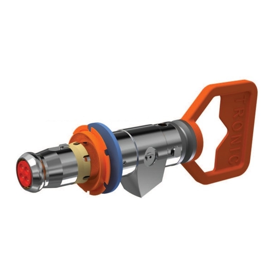
Page 41: Figure 26 Diver Operated Connector Showing Mating Features
Document No: IOM-002 Issue Date: 24/09/2020 Revision: Page: 41 of 42 Figure 26 Diver operated connector showing mating features Unrestricted... -
Page 42: Customer Comments/Feedback
Sign Off Section Name (BLOCK CAPITALS) Signature Date Please e-mail completed form to the Product Safety Officer at the following address: subsea.connectors.productsafety.gb@siemens-energy.com Unrestricted...