Advertisement
Quick Links
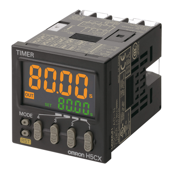
H5CX-A@-N/-L@-N
Digital Timer
INSTRUCTION MANUAL
EN
Thank you for purchasing the OMRON Product.
To ensure the safe application of the Product, read this
manual carefully before using the Product and always keep
it close at hand when the Product is in use.
OMRON Corporation
©All Rights Reserved
1148541-8B
For details, refer to the latest datasheet (Cat. No. L111).
Suitability for Use
OMRON shall not be responsible for conformity with any standards, codes, or
regulations that apply to the combination of the products in the customer's
application or use of the product.
Take all necessary steps to determine the suitability of the product for the systems,
machines, and equipment with which it will be used. Know and observe all
prohibitions of use applicable to this product.
NEVER USE THE PRODUCTS FOR AN APPLICATION INVOLVING SERIOUS
RISK TO LIFE OR PROPERTY WITHOUT ENSURING THAT THE SYSTEM AS A
WHOLE HAS BEEN DESIGNED TO ADDRESS THE RISKS, AND THAT THE
OMRON PRODUCT IS PROPERLY RATED AND INSTALLED FOR THE
INTENDED USE WITHIN THE OVERALL EQUIPMENT OR SYSTEM.
See also Product catalog for Warranty and Limitation of Liability.
Mounting and Panel-cutout Dimensions Diagram
Mounting Dimensions
(Units: mm)
Flush Mounting
H5CX-A-N/-AS-N
Front panel dimensions are the
Y92S-29 (provided)
Y92F-30 (provided)
same.
Waterproof Packing
Flush Mounting
Panel
Adapter
(51)
48
7.5
76.5
Surface Mounting
H5CX-A11@-N
Y92S-29 (order separately)
Y92F-30 (order separately)
Flush Mounting
Waterproof Packing
Panel
Adapter
H5CX
-A11@-N
100.9
103.2*
(51)
7.5
89.9
P2CF-11(-E) Front-connecting
sockets (order separately)
H5CX-L8@-N
Y92F-30 (order
Y92S-29 (order separately)
separately)
Waterproof Packing
Flush Mounting
Panel
Adapter
H5CX
-L8@-N
90
92.3*
(51)
P2CF-08(-E) Front-connecting
7.5
84.8
sockets (order separately)
*These dimensions vary with the
type of DIN track (reference value).
Application as a Timer
Basic settings can be done only with the DIP switch.
Step1
Note: H5CX-L8@-N has no DIP switch, so go to
Key-protect switch
ON
OFF
1
2
3
4
5
6
7
8
Item
OFF
ON
1
DIP switch setting
Disable
Enable
2
Refer to the table
3
Time range
on the right.
4
5
Refer to the table
Output mode
6
on the right.
7
UP/DOWN mode
UP
DOWN
8
Input signal width
20 ms
1 ms
• Default settings are all OFF.
• Turn ON pin 1 on the DIP switch (enabled).
•
DIP switch settings are updated when the
power is turned ON. (Set the DIP switch
before installation and turning ON power.)
Parameters that cannot be set with the DIP switch are set with the operation keys on the front
Step2
panel.
Note: Refer to the datasheet (Cat. No. L111) for detailed parameter settings.
● Change from RUN Mode to Function Setting Mode.
●
Set the parameters using the UD Keys.
The characters displayed in reverse video are the default settings.
When performing settings with operation keys only, set pin 1 of the DIP switch to OFF (factory setting).
If pin 1 of the DIP switch is set to ON, the setting items indicated in
Display
Parameter name
Set value
timr
Time range
*1
timm
up, down *2
UP/DOWN mode
outm
a, a-1, a-2, a-3, b,
Output mode
b-1, d, e, f, z, s *2
otim
hold/0.01 to 99.99
Output time
iflt
Input signal width
20ms,1ms *2
imod
npn, pnp *2
NPN/PNP input
colr
red, grn, org, r-g, g-r,
Display color
r-o, o-r, g-o, o-g *2
otmd
1c1c, 2c *2
Instantaneous/
time-limit
sl-h
1 to
9999
Set value upper limit
kypt
kp-1, kp-2, kp-3, kp-4,
Key protect level
kp-5, kp-6, kp-7 *2
• Models Other Than H5CX-L8E@
on-a
0
to 9999
Output ON count
alarm set value
on-c
---
Output ON count
monitor value
• H5CX-L8E@
on1a
0
to 9999
Instantaneous output 1 (OUT1)
ON count alarm set value
on2a
0
to 9999
Time-limit
output 2 (OUT2) ON
count alarm set value
on1c
Instantaneous output 1 (OUT1)
---
ON count monitor value
on2c
---
output 2 (OUT2) ON
Time-limit
count monitor value
*1 The set values for the time range are as follows:
Display
Set value
--.-- s
0.01 s to 99.99 s (default setting)
---.- s
0.1 s to 999.9 s
---- s
1 s to 9999 s
--:-- ms
0 min 01 s to 99 min 59 s
---.- m
0.1 min to 999.9 min
---- m
1 min to 9999 min
--:-- hm
0 h 01 min to 99 h 59 min
---.- h
0.1 h to 999.9 h
---- h
1 h to 9999 h
-.--- s
0.001 s to 9.999 s
*2 After reaching the last set value, the UD Keys will return
to the first set value.
SAFETY PRECAUTIONS
Keys to Warning Symbols
Indicates a potentially hazardous situation which, if not
CAUTION
avoided, is likely to result in minor or moderate injury or
in property damage.
CAUTION
Do not allow pieces of metal, wire clippings, or fine metallic
shavings or fillings from installation to enter the product. Doing so
may occasionally result in electric shock, fire, or malfunction.
Minor injury due to explosion may occasionally occur. Do not use
the Timer where subject to flammable or explosive gas.
Fire may occasionally occur. Tighten the terminal screws to the
rated torque
H5CX terminals: 6.55 to 7.97 lb-in (0.74 to 0.90 N⋅m)
P2CF socket terminals: 4.4 lb-in (0.5 N⋅m)
Minor injury due to electric shock may occasionally occur. Do not
touch any of the terminals while power is being supplied. Be sure
to mount the terminal cover after wiring.
The life expectancy of the output relay varies considerably
according to its usage. Use the output relay within its rated load
and electrical life expectancy. If the output relay is used beyond its
life expectancy, its contacts may become fused or there may be a
risk of fire. Also, be sure that the load current does not exceed the
rated load current and when using a heater, be sure to use a
thermal switch in the load circuit.
Minor electric shock, fire, or malfunction may occasionally occur.
Do not disassemble, modify, or repair the Timer or touch internal
components.
Precautions for Safe Use
1) When mounting the Timer to a panel, tighten the two mounting screws alternately, a little at a time, so as to
keep them at an equal tightness. If the panel screws are tightened unequally, water may enter the panel.
2) Store the Timer at the specified temperature. If the Timer has been stored at a temperature of less than
−10°C, allow the Timer to stand at room temperature for at least 3 hours before use.
3) Mounting the Timer side-by-side may reduce the life expectancies of internal components.
4) Use the Timer within the specified ranges for the ambient operating temperature and humidity.
Panel-cutout Dimensions Diagram
•
(Units: mm)
H5CX-AD-N/-ASD-N
Y92F-30
Y92S-29 (provided)
Standard panel cutout is shown in the
Waterproof Packing
(provided)
Panel
following diagram (conforms to DIN
Flush Mounting Adapter
43700). A space of 15 mm or greater
(a panel cut-out distance of 60 mm or
greater) is recommended towards
the Adapter's hook side to enable
(51)
easier mounting work.
7.5
57.5
P3GA-11 (order separately)
Back-connecting Socket
1. The thickness of a mounting panel
should be 1 to 5 mm.
2. It is possible to mount Timers side by
side by mounting Adapters. (But only
towards the non-hook side.)
P3G-08 (order separately)
Back-connecting Socket
3. If the Timers are mounted side by side,
water resistance will be lost.
Package Contents
• Digital Timer
• Instruction manual (this document)
• DIP switch label (Except for H5CX-L8@)
• Mounting Adapter, Waterproof Packing,
Terminal Cover (except for H5CX-A11@
and H5CX-L8@)
Display in RUN mode.
•
Step1
(except for Z mode)
Step2
.
1234
Present value
s
2000
s
Set value
SET
Pin 2
Pin 3
Pin 4
Time range
0.001 s to 9.999 s
ON
ON
ON
OFF
OFF
OFF
0.01 s to 99.99 s
ON
OFF
OFF
0.1 s to 999.9 s
OFF
ON
OFF
1 s to 9999 s
ON
ON
OFF
0 min 01 s to 99 min 59 s
OFF
OFF
ON
0.1 min to 999.9 min
ON
OFF
ON
0 h 01 min to 99 h 59 min
Step2
OFF
ON
ON
0.1 h to 999.9 h
Pin 5
Pin 6
Output mode
A Mode (Signal-ON delay (I):
OFF
OFF
Power recycle)
A-2 Mode (Power-ON delay (I):
ON
OFF
Power recycle)
OFF
ON
E Mode (Interval: Power recycle)
F Mode ( Cumulative : Power retain)
ON
ON
3 s min.
MODE
Function
RUN mode
Power ON
setting mode
3 s min.
MODE
will not be displayed.
Step3
Comments
---
Note: Refer to the datasheet (Cat. No. L111) for detailed parameter settings.
● Change from RUN Mode to Function Setting Mode.
---
Only modes a-2, b, e, and z can be
selected for H5CX-L8E@.
●
(If the output time is set to 0.00, hold
is displayed.)
Displayed for modes a, a-1, a-2,
a-3, b, b-1 and s only. Unit: second
Displayed only for models other than H5CX-L8E@.
Only displayed for the H5CX-A@ and
H5CX-A11@.
Displayed only for models with
terminal blocks.
Displayed only for the H5CX-L8E@.
---
---
× 1,000
The monitor value is only displayed.
× 1,000
It cannot be set.
× 1,000
× 1,000
The monitor value is only displayed.
× 1,000
It cannot be set.
The monitor value is only displayed.
× 1,000
It cannot be set.
Display in RUN mode. (Z mode)
•
12.34
Present value
S
10
ON duty
SET1
*1 The set values for the time range are the same as for Timer operation.
*2 After reaching the last set value, the UD Keys will return to the first set value.
MODE
MODE
12.34
Present value
S
18.50
Cycle time
SET2
S
5) Do not use in the following locations:
• Locations subject to sudden or extreme changes in temperature.
• Locations where high humidity may result in condensation.
• Locations with excessive vibration or shock.
• Locations subject to water.
• Locations subject to oil.
6) Do not use this Timer in dusty environments, in locations where corrosive gasses are present, or in locations
subject to direct sunlight.
7) Install the Timer well away from any sources of static electricity, such as pipes transporting molding
materials, powders, or liquids.
8) Internal elements may be destroyed if a voltage outside the rated voltage range is applied.
9) Wire terminal polarity correctly.
10) Separate the Timer from sources of noise, such as devices with input signals from power lines carrying
noise, and wiring for I/O signals.
11) Do not connect more than two crimp terminals to the same terminal.
12) Up to two wires of the same size and type can be inserted into a single terminals.
13) Use the specified wires for wiring. Applicable Wires: AWG 18 to AWG 22, solid or twisted, copper
14) Install a switch or circuit breaker that allows the operator to immediately turn OFF the power, and label it
to clearly indicate its function.
15) When the Timer is operated with no-voltage input (NPN input), approximately 14 V is output from the
input terminals. Use a sensor that contains a diode.
16) Use a switch, relay, or other contact so that the rated power supply voltage will be reached within 0.1
seconds. If the power supply voltage is not reached quickly enough, the Timer may malfunction or outputs
may be unstable.
17) Use a switch, relay, or other contact to turn the power supply OFF instantaneously. Outputs may
malfunction and memory errors may occur if the power supply voltage is decreased gradually.
18) When changing the set value during a timing operation, the output will turn ON if the set value is changed
as follows because of the use of a constant read-in system:
Elapsed time (UP) mode: Present value ≥ Set value
Remaining time (DOWN) mode: Elapsed time ≥ Set value (The present value is set to 0.)
When in the remaining time mode, the amount the set value is changed is added to or subtracted from the
present value. When the set value is 0, the output turns ON the moment the signal is input. The reset
operation turns OFF the output.
19) Do not use organic solvents (such as paint thinners or benzine), strong alkali, or strong acids. They will
damage the external finish.
20) Confirm that indications are working normally, including the backlight LED, and LCD. The indicator LEDs,
LCD, and resin parts may deteriorate more quickly depending on the application environment, preventing
normal indications. Periodic inspection and replacement are required.
21) The waterproof packing may deteriorate, shrink, or harden depending on the application environment.
Periodic inspection and replacement are required.
Precautions for Correct Use
1) H5CX models with a 24-VAC/12 to 24-VDC power supply use a transformer-free power supply method in
which the power supply terminals are not isolated from the signal input terminals. If a non-isolating DC
power supply is used, unwanted current paths may occasionally burn or destroy internal components
depending on the wiring. Always check the wiring sufficiently before use.
2) An inrush current of approx. 10 A will flow for a short time when the power supply is turned ON. If the
capacity of the power supply is not sufficient, the Timer may not start. Be sure to use a power supply
with sufficient capacity.
3) Maintain voltage fluctuations in the power supply within the specified operating voltage range.
4) To allow for the startup time of peripheral devices (sensors, etc.), the Timer starts timing operation
between 200 to 250 ms after power is turned ON. For this reason, in operations where timing starts
from power ON, the time display will actually start from 249 ms. If the set value is 249 ms or less, the
time until output turns ON will be a fixed value between 200 and 250. The present value display will start
from 250 ms. (Normal operation is possible for set values of 250 ms or more.) In applications where a
set value of 249 ms or less is required, use start timing with signal input.
Ratings (Specifications)
Power supply voltage
100 to 240 VAC, 50/60 Hz (Other than H5CX-@D)
12 to 24 VDC/24 VAC, 50/60 Hz (H5CX-@D)
Allowable voltage fluctuation range 85% to 110% of rated supply voltage (12 to 24 VDC: 90% to 110%)
Power consumption
Approx. 6.2 VA at 100 to 240 VAC,
Approx. 5.1 VA/2.4 W at 24 VAC/12 to 24 VDC
−10 to 55°C (−10 to 50°C if Timers are mounted side by
Operating temperature range
side) (with no icing or condensation)
−25 to 70°C (with no icing or condensation)
Storage temperature range
Operating humidity range
25% to 85%
Altitude
2,000 m max.
Recommended fuse
T2A, 250 VAC, time-lag, low-breaking capacity
Weight
Approx. 115 g (main unit only)
Installation environment
Over-voltage category III, pollution degree 2 (IEC 61812-1)
Input method
ON impedance: 1 kΩ max. (Leakage current: 12 mA when 0 Ω)
No-voltage Input
ON residual voltage: 3 V max.
OFF impedance: 100 kΩ min.
Voltage Input
High (logic) level: 4.5 to 30 VDC
48
Low (logic) level: 0 to 2 VDC (Input resistance: approx. 4.7 kΩ)
No-voltage (NPN) input/voltage (PNP) input (switchable)
Control output
Contact output
250 V AC, 5A (resistive load)
30 V DC, 5A (resistive load)
Solid state output
Open collector, 30 VDC max.,100 mA max.
Residual voltage: 1.5 VDC max.
(Effective value: Approx. 1 VDC)
Leakage current: 0.1 mA max.
Electrical life of relay
100,000 operations (at an ambient temperature of 23°C)
Mechanical life of relay
10,000,000 operations (at an ambient temperature of 23°C)
Degree of protection
IEC IP66, UL508 Type 4X *
*
Individual mounting: Degree of protection on the front panel of the Timer conforms to UL 508
n Units mounted
Type 4X when all of the following conditions are satisfied:
side-by-side
•
The Y92S-29 waterproof packing and Y92F-30 mounting adapter are used with the Timer.
Use only these parts for replacement.
•
A
The Timer is mounted on the flat surface of an enclosure that is rated and marked "Type
4X for Indoor Use Only."
+1
A=(48n−2.5)
−0
Conformance to EN/IEC Standards
When conforming to EMC standards, refer to the information provided in this Instruction Manual for cable
selection and other conditions.
This is a class A product. In residential areas it may cause radio interference, in which case the user may be
required to take adequate measures to reduce interference.
Basic insulation is provided between the power supply and input terminals. (No insulation is provided between
the power supply and input terminals for the H5CX-@D-N.)
Basic insulation is provided between power supply and output terminals, and between input and output
terminals. When double insulation or reinforced insulation is required, apply double insulation or reinforced
insulation as defined in IEC 60664 that is suitable for the maximum operating voltage with clearances or solid
insulation.
Application as a Twin Timer
First, switch to a Twin Timer
Power ON
Change to "Twin Timer"
using the
U
Key.
Timer/Twin Timer
U1
MODE +
selection mode
Press for 1 s.
func
tim
twn
RUN mode.
tim
Timer
Twin Timer
U1
MODE +
Press for 1 s.
MODE
dip
DIP switch monitor
1off
Basic settings can be done only with the DIP switch.
Note: H5CX-L8@ has no DIP switch, so go to
Step3
Key-protect switch
ON
OFF
1
2
3
4
5
6
7
8
Item
OFF
ON
1
DIP switch setting
Disable
Enable
2
OFF-time range
Refer to the table on the right.
3
4
ON-time range
Refer to the table on the right.
5
6
Output mode
Repeat cycle-OFF start Repeat cycle-ON start
7
UP/DOWN mode
DOWN
UP
8
Input signal width
20 ms
1 ms
• Default settings are all OFF.
• Turn ON pin 1 on the DIP switch (enabled).
• DIP switch settings are updated when the power is turned ON.
(Set the DIP switch before installation and turning on power.)
Parameters that cannot be set with the DIP switch are set with the operation keys on the front
panel.
Power ON
Set the parameters using theNUD Keys.
The characters displayed in reverse video are the default settings.
When performing settings with operation keys only, set pin1 of the DIP switch to OFF (factory setting).
If pin 1 of the DIP switch is set to ON, the setting items indicated in
Display
Parameter name
Set value
oftr
OFF time range
*1
ontr
*1
ON time range
timm
up, down *2
UP/DOWN mode
totm
toff, ton, tof1, ton1
Twin Timer Output
mode
*2
iflt
20ms,1ms *2
Input signal width
imod
npn, pnp *2
NPN/PNP input
colr
red, grn, org, r-g, g-r,
Display color
r-o, o-r, g-o, o-g *2
otmd
1c1c, 2c *2
Instantaneous/time-limit
sl1h
1 to
9999
Set value upper limit 1
sl2h
1 to
9999
Set value upper limit 2
kypt
kp-1, kp-2, kp-3, kp-4,
Key protect level
kp-5, kp-6, kp-7 *2
• Models other than H5CX-L8E@
on-a
0
to 9999
Output ON count
alarm set value
on-c
---
Output ON count
monitor value
• H5CX-L8E@
on1a
0
to 9999
Instantaneous output 1 (OUT1)
ON count alarm set value
on2a
0
to 9999
Time-limit output 2 (OUT2) ON
count alarm set value
on1c
---
Instantaneous output 1 (OUT1)
ON count monitor value
on2c
---
Time-limit output 2 (OUT2) ON
count monitor value
5) The input signal will not be accepted after 5 to 505 ms has elapsed from when the power supply is turned
OFF.
6) Inrush current generated by turning ON or OFF the power supply may deteriorate contacts on the power
supply circuit. Turn ON or OFF to a device with the rated current of more than 10 A.
7) Make sure that all settings are appropriate for the application. Unexpected operation resulting in property
damage or accidents may occur if the settings are not appropriate.
8) Do not leave the Timer for long periods of time at a high temperature with output current in the ON state.
Doing so may result in the premature deterioration of internal components (e.g., electrolytic capacitors).
9) EEPROM is used as memory when the power is interrupted. The write life of the EEPROM is 100,000
writes. The EEPROM is written when the power is turned OFF or when switching from function setting,
mode or Timer/Twin Timer selection mode to run mode.
10) Dispose of the product according to local ordinances as they apply.
11) Attach the front panel when using the Timer. The latches in the middle of each of four sides secure the
front panel to the main body. To remove the panel, widen the four latches and pull the panel toward you.
To mount the panel, fit all four latches correctly into the slots on the main body.
Precautions for Compliance with UL Standards and CSA Standards
Notice to Users of the H5CX in the USA and Canada
Please use the following installation information instead of the general information in the instruction manuals in
order to use the product under certified conditions of UL and CSA when the product is installed in the USA or
Canada. These conditions are required by NFPA 70, National Electrical Code in the USA and the Canadian
Electrical Code, Part I in Canada and may vary from information given in the product manuals or safety
precautions.
• Installation in a Panel
H5CX is normally installed on a flat surface in an operation panel. Use a Type 1 Enclosure for the operation
panel.
• Use an isolated source for power input for the H5CX-@D.
Use the isolated source for Inputs and for Solid State Output.
• Environment
Surrounding Air Temperature: −10 to 40°C
• Power supply: The inputs are non-isolated. (Applicable to H5CX-@D only)
The same power supply as the main power source should be used for that for input.
• Accessories (Order Separately)
Track Mounting/Front Connecting Socket
Flush Mounting Adapter
Waterproof Packing
Front Panel (4 digits)
Display Section
1. Key Protect Indicator (orange)
2. Control Output Indicator (orange)
3. Reset Indicator (orange)
4. Present Value Display (Main Display)
(Character height: 12 mm, red*)
*Characters on models with terminal
blocks can be switched between red,
green, and orange.
5. Time Unit Indicators (If the time range
is 0 min, 0.0 min, 0 h, 0.0 h, or 0 h 0
min, these indicators flash to indicate
timing operation.)
6. Set Value Display (Sub-display)
(Character height: 6 mm, green)
7. Set Value 1, 2 Indicator
Operation Key
8. Mode Key (Changes modes and setting items)
9. Reset Key (Resets present value and output)
10. Up Keys 1 to 4
11. Down Keys 1 to 4
Wire properly after checking the specifications of the power supply
voltage.
Do not connect unused terminals.
H5CX-A-N/-AD-N
0V
6
7
8
1
2
3
Contact output
(−)
(+)
H5CX-A11-N/-A11D-N
Reset
Signal
Gate
Unused
0V
Display in RUN mode.
•
Terminals 2 and 3 of the H5CX-A11D-N
12.34
are connected internally.
s
Present value
H5CX-L8-N/-L8D-N
.
10
00
OFF Set value
s
SET1
Signal
MODE
MODE
Reset
12.34
s
Present value
.
18
50
ON Set value
s
SET2
Terminals 1 and 2 of the H5CX-L8D-N
are connected internally.
.
H5CX-L8E-N/-L8ED-N
Internal circuit
Instantaneous
contact output
OUT1
Pin 2
Pin 3
OFF-time range
0.01 s to 99.99 s
OFF
OFF
Input Connections
ON
OFF
0.1 s to 999.9 s
No-voltage Inputs (NPN Inputs)
OFF
ON
1 s to 9999 s
ON
ON
0 min 01 s to 99 min 59 s
Open Collector
ON-time range
Pin 4
Pin 5
PLC or
sensor
OFF
OFF
0.01 s to 99.99 s
ON
OFF
0.1 s to 999.9 s
OFF
ON
1 s to 9999 s
ON
ON
0 min 01 s to 99 min 59 s
Note: Operate with transistor ON
Voltage Inputs (PNP Inputs)
No-contact Input
(NPN Transistor)
Sensor
3 s min.
MODE
Function
RUN mode
setting mode
3 s min.
MODE
Note: Operate with transistor OFF
will not be displayed.
Comments
---
When the key-protect switch is ON,
---
individual key operations can be disabled
---
to prevent setting errors according to the
toff
and ton can be
Only modes
key protect levels (KP-1 to KP-7) shown
selected for H5CX-L8E@.
in the following table.
Displayed only for models other than H5CX-L8E@.
* Key protect levels are set in function
setting mode.
Displayed only for the
H5CX-A@ and H5CX-A11@.
Displayed only for models with
Level
terminal blocks.
KP-1 (default setting)
Displayed only for H5CX-L8E@.
KP-2
KP-3
KP-4
---
KP-5
KP-6
---
KP-7
---
* Changing mode to Timer/Twin Timer selection mode or function setting mode.
× 1,000
The following displays will appear if an error occurs.
Main
Sub-display
The monitor value is only displayed.
display
× 1,000
It cannot be set.
e1
e2
× 1,000
e2
× 1,000
e3
No change
*2
*1 This includes times when the life of the EEPROM has expired.
*2 The normal display and e3 will appear alternately.
The monitor value is only displayed.
When the Reset Key is pressed, e3 will no longer be displayed even if the alarm set value is exceeded.
(Monitoring is possible, however, because the counter will continue without clearing the output ON count.)
× 1,000
It cannot be set.
The monitor value is only displayed.
× 1,000
It cannot be set.
OMRON EUROPE B.V.
Wegalaan 67-69-2132 JD Hoofddorp, The Netherlands
Tel: (31)2356-81-300/Fax: (31)2356-81-388
OMRON ELECTRONICS LLC (U.S.A.)
Tel: (1) 847-843-7900/Fax: (1) 847-843-7787
OMRON ASIA PACIFIC PTE. LTD. (SINGAPORE)
Tel: (65) 6835-3011/Fax: (65) 6835-2711
OMRON (CHINA) CO., LTD.
Tel: (86) 21-5037-2222/Fax: (86) 21-5037-2200
11-pin
P2CF-11
11-pin, finger-safe type
P2CF-11-E
8-pin
P2CF-08
8-pin, finger-safe type
P2CF-08-E
---
Y92F-30
---
Y92S-29
Light gray (Munsell 5Y7/1)
Y92P-CXT4G
White
Y92P-CXT4S
Black
Y92P-CXT4B
Nomenclature
1
2
3
8
9
Terminal Arrangement
H5CX-AS-N/-ASD-N
0V
6
7
8
9
9
Terminals 1 and 6 of the
Terminals 1 and 6 of the
H5CX-AD-N are
H5CX-ASD-N are
connected internally.
connected internally.
1
2
3
4
5
4
5
Solid state output
*
(−)
(+)
H5CX-A11S-N/-A11SD-N
Reset
Signal
Gate
Internal circuit
Internal circuit
6 7
6 7
5
5
Unused
4
8
4
8
3
9
0V
3
9
2
10
Contact output
2
10
1
11
1
11
Solid state output
Unused
Unused
(−)
(+)
(−)
(+)
Terminals 2 and 3 of the H5CX-A11SD-N
are connected internally.
H5CX-L8S-N/-L8SD-N
Internal circuit
Internal circuit
Signal
Unused
4
5
4
5
Reset
3
6
3
6
2
7
2
7
Contact output
Solid state output
1
8
1
8
0V
0V
(−)
(+)
(−)
(+)
Terminals 1 and 2 of the H5CX-L8SD-N
are connected internally.
*
Internal circuit
NPN Output
PNP Output
4
5
3
6
Load
Load
Time-limit contact
+
+
output OUT2
2
7
Power for load
Power for load
1
8
With Inductive Load
Timer
(−)
(+)
Inductive
load
+
Power for load
Voltage Output
Contact Input
Sensor
Note: Operate with transistor ON
Note: Operate with relay ON
Contact Input
No-contact Input
(PNP Transistor)
Sensor
Note: Operate with transistor ON
Note: Operate with relay ON
Key-protect Switch Settings
ON (enable)
OFF (disable)
(setting when
purchased.)
Key protect indicator
Display switch in the run mode
Reset Key
Up/Down Key
Mode change*
Valid
Valid
Valid
Invalid
Valid
Invalid
Invalid
Valid
Valid
Valid
Invalid
Invalid
Valid
Invalid
Invalid
Invalid
Invalid
Invalid
Invalid
Invalid
Invalid
Invalid
Valid
Valid
Invalid
Invalid
Invalid
Valid
Self-diagnostic Functions
Output
Set value after
Error
Correction method
status
reset
Either press the Reset Key
Not lit
CPU error
No change
OFF
or reset the power supply.
Not lit
Memory error (RAM)
OFF
Reset the power supply.
No change
sum
Memory error (EEPROM)*1
OFF
Reset Key
Factory setting
Output ON count alarm
No
Reset Key
No change
set value exceeded
change
4
5
6
7
10
11
*
*
Advertisement

Related Manuals for Omron H5CX-A Series


Summary of Contents for Omron H5CX-A Series
- Page 1 21) The waterproof packing may deteriorate, shrink, or harden depending on the application environment. life expectancy, its contacts may become fused or there may be a OMRON shall not be responsible for conformity with any standards, codes, or Track Mounting/Front Connecting Socket...
- Page 2 ---.- h 0.1h〜999.9h ※2:設定値が最後尾に来たとき、UDキーで再び先頭に戻ります。 ■営業時間: 9:00 〜 12:00/13:00 〜 19:00 ( 土・日・祝祭日は17:00まで) ---- h 1h〜9999h MODE MODE ■営 業 日:年末年始を除く -.--- s 0.001s〜9.999s 12.34 ●F A Xによるお問い合わせ 計時値 ※2:設定値が最後尾に来たとき、UDキーで再び先頭に戻ります。 テクニカルセンタ お客様相談室 FAX 055-982-5051 周期時間 18.50 SET2 ●インターネッ トによるお問い合わせ/FAQ (よ く あるご質問) の検索はオムロン Industrial Webをご利用く ださい。 http://www.fa.omron.co.jp/...