Datalogic Magellan 8300 Technical Manual
Hide thumbs
Also See for Magellan 8300:
- Product reference manual (558 pages) ,
- Quick start manual (18 pages) ,
- Quick reference manual (21 pages)
Table of Contents
Advertisement
Advertisement
Table of Contents

Related Manuals for Datalogic Magellan 8300


Summary of Contents for Datalogic Magellan 8300
- Page 1 Magellan 8300/8400 Technical Guide...
- Page 2 Should future revisions of this manual be published, you can acquire printed versions by contacting your Datalogic representative. Electronic versions may either be downloadable from the Datalogic website (www.scanning.data- logic.com) or provided on appropriate media.
- Page 3 Product Reference Guide...
-
Page 5: Table Of Contents
Table of Contents Chapter 1. Introduction ................... 1-1 Technical Support ......................1-1 Datalogic Website Support ..................1-1 Reseller Technical Support ..................1-1 Telephone Technical Support ................... 1-1 ..........................1-2 Scanner and Scanner/Scale Nomenclature ..............1-2 Connections ........................ 1-3 Weighing ........................1-4 Warm-Up Time ...................... - Page 6 Scale Error Reporting ....................3-6 Chapter 4. Calibration ..................4-1 Description of Calibration Sequence ................4-2 Motion Test ......................... 4-3 Preparing the Scanner/Scale for Calibration ..............4-4 Calibrating the Scale ....................4-4 Calibration Verification (Kilograms) ................. 4-7 Increasing-Load Test (Phase 1) ................4-7 Shift Test (Metric) ....................
-
Page 7: Chapter 1. Introduction
Telephone Technical Support If you do not have internet or email access, you may contact Datalogic technical support at (541) 349-8283 or check the back cover of your man- ual for more contact information. -
Page 8: Scanner And Scanner/Scale Nomenclature
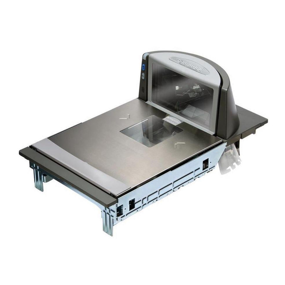
Scanner and Scanner/Scale Nomenclature Controls, indicators and other nomenclature are shown in Figure 1-1 Figure 1-1. Scanner/Scale Nomenclature Weighing Surface — Lean Oversize Produce Here Scanner LED All Weighs™ Platter Vertical Window Bonnet Horizontal Window Volume/Tone Push Button Scale Zero Push Button Produce Bar Speaker (Beeper) Port... -
Page 9: Connections
Connections Connections Two connector panels are located on either side of the scanner as shown in . The appearance of these panels will vary depending upon the Figure 1-2 factory options purchased with your model. Additionally, a service “pig- tail” extends from the scanner’s base to connect the control panel cable from the Bonnet area. -
Page 10: Weighing
Weighing Specifications for scale capacity, settling time, minimum and maximum static weight, zeroing, and warm-up time are given below. Rated Weight Capacity The scale’s operational weight capacity is: • 15.000 kilograms, displayed in 0.005 increments. Minimum Increment The minimum weight that can be accurately measured by the scale is 0.005 kg. -
Page 11: Warm-Up Time
Weighing Warm-Up Time There are two pertinent warm-up times that apply to the scanner or scan- ner/scale: The two warm-up periods can be performed concurrently, thereby reducing the total required warm-up time to 60 minutes. NOTE Thermal Equilibrium When the unit is moved from a cooler temperature (such as a storage area) to a warmer environment (such as a checkstand location), 60 minutes must be allowed to acclimate the unit to ambient conditions prior to cali- bration or operation. -
Page 12: Electrical Specifications
(86,080 LUX) Humidity Hot / Wet 40°C / 95% RH Hot / Dry 40°C / 15% RH Spill Proof (Datalogic MS-0006-13-0004) Cold / Dry 10°C / 1 5% RH Warm / Wet 25%C / 50% RH Storage +70 C +158 F... -
Page 13: Power Supply
Electrical Specifications Power Supply Power Off the Terminal (P.O.T) Certain units can receive power directly from the terminal (P.O.T.). A USB adapter “brick” connects the scanner to IBM-USB 12V ports. Power supplied from the terminal does not include auxiliary power for alterna- tive scales. -
Page 14: Agency Compliances
Agency Compliances The scanner and scanner/scale meets or exceeds the requirements for its device type as set forth by the following agencies and regulations: COUNTRY COMPLIANCE COMMENTS Electrical United States UL 60950 State of California Energy Efficiency Standard Canada CAN/CSA 60950 Europe TÜV EN 60950 Mexico... - Page 15 EC Countries Type Approval Cert Mexico Puerto Rico Same as USA Singapore Spring Singapore OIML R76 Russia ® Contact Datalogic Product Marketing at (541) 683-5700, or your Data- logic representative for a complete listing of approvals for other countries. Technical Guide...
- Page 16 NOTES 1-10 ® Magellan 8300/8400...
-
Page 17: Chapter 2. Site Preparation And Installation
Scanner and scanner/scale models (reference Figure 2-1) are available in different lengths, allowing them to fit with little or no modification into ® openings cut for previously installed scanners such as Datalogic Magel- ® ® scanners, or NCR scanner models 7820/24 and 7870. Other mod- els are designed for applications with smaller footprint requirements. - Page 18 Figure 2-1. Model Examples Scanner ONLY models Scanner/Scale models Model 8301/8401 Short Model 8302/8402 Model 8304/8404 Medium Medium Model 8303/8403 Model 8305/8405 Long Long Figure 2-2. Flanged and Shelf Model Examples Flange Model Shelf Model Flanges Figure 2-3. Produce Bar and Produce Rail Produce Produce Bar Option...
-
Page 19: Pre-Installation Considerations
Pre-Installation Considerations Pre-Installation Considerations It should be noted that the scope of this manual does not encompass all factors related to worker safety and checkstand design. It does, however, offer a list of considerations that may be helpful in ensuring greater safety and productivity. -
Page 20: Scanner Installation
5. Select a design which encourages the cashier to slide products across the scanner rather than gripping and lifting. Make sure the horizon- tal surface of the scanner is flush with all surrounding surfaces. 6. Choose a design which integrates the scanner and scale to eliminate extended reaches and lifts during weighing tasks. -
Page 21: Scanner Usage
Scanner Usage Scanner Usage 1. Minimize handling of heavy/bulky products. Leave these items in the cart and use an alternative entry method such as key entry of short PLUs, or handheld scanning. 2. Regularly train cashiers in proper scanning methods and ergonomics principles, such as: •... - Page 22 Service Access Requirements — Routine operations such as ‘zero- ing’ and calibration do not require removal of the scanner from the check- stand or disassembly of the product. The installer should plan service access for the AC/DC Power Supply and cables. Recommended Power Installation —...
-
Page 23: Ventilation And Spacing
Ventilation and Spacing Vertical Clearance — Provision must be made to allow adequate space above the scanner bonnet for removal and replacement of an L-shaped platter. Optimal clearance permits the platter to be grasped at its top verti- cal edge and lifted for removal without obstruction (such as a fixed key- board mount or any type of enclosure). - Page 24 • A source of air that provides adequate cooling by convective air flow. DO NOT place the scanner in a close-fitting, fully enclosed checkstand. Pro- vide a MINIMUM of 16 square inches (103.2 square centimeters) of air intake from below the installation for sufficient convective cooling. NOTE If motors, conveyor belts, or other heat producing equipment are located near the scanner, forced air ventilation may be required.
-
Page 25: Power Installation
Power Installation Power Installation Reference the wiring diagram in Figure 2-6 for the recommended fusing arrangement. Grounding The AC/DC Power Supply should have an AC outlet with a clean earth ground. If you are not sure how to verify the amount of electrical noise (interference) on the power line, ask a qualified electrician to measure the input line voltage. -
Page 26: Liquid Spills And Moisture
Liquid Spills and Moisture Select a checkstand design which allows fluids to flow through, and directs liquids away from any electronic equipment or storage areas. Counter Cutout The most important consideration when planning the counter opening for the scanner is the operator’s comfortable reaching distance. The ideal, ergonomically sound installation allows items to be directed within easy reach, and a scanning area requiring no lifting or special orientation of items. - Page 27 Counter Cutout 3. Install the AC/DC Power Supply, the Remote Scale Display cable (if Remote Display is used) and the interface cable(s) observing the fol- lowing: Interface cables (and display cable, if applicable) should be routed away from all highly inductive electrical devices, like motors and conveyor belts, and even away from the unit’s power cable if possible.
- Page 28 Figure 2-7. Typical Checkstand Design & Cutout Location Remote Display Conveyor POS Terminal & Printer Optional Item Diverter Deadplate 6.3" (16.0cm) Scanner Keyboard Cash Drawer (Below Scanner) Scan & Bag Well (Optional) Check Writing Flush — Correct Stand Take-Away (Optional) Belt Bagging Above Flush —...
- Page 29 Counter Cutout Figure 2-8. Medium Shelf Models 8302/8304/8402/8404 Cutout Dimensions Models 8302/8304/8402/8404 (Medium Shelf) Optional Leveling Feet Minimum Cutout Max. Radius = 0.25" Dimensions (0.635cm) 15.825" (40.2cm) min. 11.625" (29.53cm) min. 1.76" Leveling (4.47cm) Feet 6.89" (17.5cm) Models 8302/8304/8402/8404 (Medium Shelf) Supports 4.08"...
- Page 30 Figure 2-10. Medium Flanged Models 8302/8304/8402/8404 Cutout Dimensions Models 8302/8304/8402/8404 (Medium Flanged) 18.00" (45.7cm) Minimum Cutout Dimensions 16.625" Rail Max. Radius = 0.25" (42.23cm) (0.635cm) 3.06" (7.77cm) 0.75" (1.905cm) 11.625" (29.53cm) (Center Line) Rail 3.06" If leveling feet are needed, 0.75"...
- Page 31 Counter Cutout Figure 2-12. Long Shelf Models 8303/8305/8403/8405 Cutout Dimensions Models 8303/8305/8403/8405 (Long Shelf) Optional Leveling Feet Cutout Max. Radius = 0.25" (0.635cm) 17.87" (45.4cm) 11.625" (29.53cm) 1.76" Leveling (4.47cm) Feet 6.89" (17.5cm) Models 8303/8305/8403/8405 (Long Shelf) Supports 10.36 cm) 4.08"...
- Page 32 Figure 2-14. Long Flanged Models 8303/8305/8403/8405 Cutout Dimensions Model 8303/8305/8403/8405 (Long Flanged) Cutout 20.00" (50.8cm) Max. Radius = 0.25" 18.625" Rail (0.635cm) 4x (47.308cm) 3.06" (7.77cm) 0.75" (1.905cm) 11.625" (Center Line) (29.53cm) Rail 3.06" (7.77cm) 0.75" If leveling feet are needed, (1.905cm) use the placement shown here, 0.375"...
-
Page 33: Installation Overview
Installation Overview Installation Overview The preceding Site Preparation Overview dealt with installed location and counter preparations to accommodate the scanner or scanner/scale. Having completed those steps, physical installation of the scanner or scan- ner/scale can begin. The following instructions apply to all models. This chapter describes: 1. - Page 34 • Carefully lift off the L-Platter as shown in and remove Figure 2-22 the protective foam pieces securing the weigh mechanism. Set the platter back in place. For added protection during shipment, the L-Platter is covered with a tight- fitting layer of vinyl. This vinyl layer MUST BE REMOVED before placing the unit into service.
-
Page 35: Scale Diagnostic Mode
Installation Overview Scale Diagnostic Mode To enter Scale Diagnostic Mode, press the Scale Zero Push Button for approximately four seconds. Six rapid tones will be sounded, indicating the unit is leaving normal operation and entering Scale Diagnostic Mode. The Remote Display will flash a ‘1’ across the display while the dignostic routine is being run. -
Page 36: Remote Scale Display Placement/Installation
provides physical dimensions for the AC/DC Adapter (part Figure 2-16 number 8-0582). Figure 2-16. Physical Measurements: AC/DC Adapter 1.23" (3.1 cm) Remote Scale Display Placement/Installation The modular Remote Display is designed so that single display heads can be stacked to form a dual display as shown in Figure 2-17a in order to address the specific viewing needs of both the customer and the cashier. -
Page 37: Viewing Angle
Remote Scale Display Placement/Installation Viewing Angle The optimum display angle is directly facing the viewer. Tilt and rotatioin adjustments can be made as shown in Figure 2-17b. To ensure that dis- plays are easily readable for customers/cashiers of average height, display heads should be between 48”... -
Page 38: Remote Display Cabling
Remote Display Cabling Your installation should also take into account the routing of Remote Dis- play cabling. Ensure that distance and obstacles spanned by the routed cable will not kink, pinch or stretch it. Also keep in mind you may need to drill a hole through which to route it. - Page 39 Remote Scale Display Placement/Installation Figure 2-18. Physical Measurements: Remote Display 18.5mm Dual Display Single Display 28.4mm 60mm 60mm 112mm 112mm 329mm 264mm 292.5mm 325mm 227.5mm 116.39mm 116.39mm 25.5mm 41.99mm 85.1mm 5. Feed the entire length of the Remote Scale Display interface cable through the cable routing hole so that the assembled Remote Scale Display can be positioned over the mounting screw holes.
- Page 40 Figure 2-19. Remote Scale Display Mounting Mounting Example Dual Display Heads Single Display Head (optional cable routing) Figure 2-20. Remote Scale Display Mounting Template 116.39mm 41.99mm 85.1mm 25.5mm 2-24 ® Magellan 8300/8400...
-
Page 41: Set-Up & Installation
Set-Up & Installation Set-Up & Installation These setup and installation procedures assume that you have already pre- pared your checkstand to receive the scanner or scanner/scale. If you have not already made the counter cutout and routed power and interface cables, do so now as described in the previous instructions. - Page 42 Figure 2-21. Connecting Cables to the Scanner/Scale Control Panel Service Loop Scanner Right Profile Scanner Left Profile 0.00 EAS Port Aux. Port Power POS Terminal Remote Display Scale Host EAS PORT AUXILIARY PORT POWER POS TERMINAL REMOTE DISPLAY SCALE HOST ·...
-
Page 43: Installation
Set-Up & Installation Installation 1. Make sure that all cables are firmly attached (except that the AC/ DC power supply should not be connected to the AC outlet yet). Reference Figure 2-21. 2. Remove the platter to gain access to the interior lift handle. Grasp the platter in the positions shown in Figure 2-22 and gently lift it... - Page 44 3. Rotate the Interior Lift Handle up as shown in Figure 2-23 hook the fingers of both hands in the lift handles indicated. DO NOT attempt to lift the unit using the plastic edges, scale frame, or any features other than the lift handles. 4.
-
Page 45: Chapter 3. Problem Isolation
Chapter 3 Problem Isolation In the event of a suspected functional problem, use the troubleshooting references provided in this chapter. This useful information will help you to identify and resolve the cause of the problem. The scanner/scale has a number of features that indicate when a scanner or scale problem occurs. -
Page 46: Diagnostic Procedures
Operational Tests These are the tests that run continually during Normal Operation and Sleep Mode. Firmware checks all subsystems, accessory connections and the POS interface to verify everything is operating normally. If a problem is detected at any time, a long, low tone is sounded, an error code is shown on the 7-segment display, and operation may be halted. -
Page 47: Error Codes
Error Codes Error Codes If an error is detected, the scanner will sound a long low tone (for one sec- ond) and alternately flash its LEDs, indicating a failure. Following the long low tone, an error code will appear on the 7-segment display (refer to ). - Page 48 Table 3-1. Error Codes Error Probable Cause Corrective Action Code No POS interface has been selected (Null interface). See Chapter 5, Configuration Interface Type to select the required interface using programming Blinking bar codes. Chapter 5, Programming, for details about configuring the Configuration Error scanner using programming bar codes.
- Page 49 Error Codes Figure 3-1. 7-Segment LED Display Vertical Window Seven-Segment Display Horizontal Window Technical Guide...
-
Page 50: Scale Error Reporting
Scale Error Reporting Scale diagnostics uses the Remote Scale Display and the Zero Status lamp to communicate specific scale failures. The following chart shows the Remote Display messages, the Scale Status lamp indication, the problem that the scale is experiencing and what action should be taken. When troubleshooting, always remember to check all cable connections first before proceeding with other problem isolation steps. - Page 51 Scale Error Reporting Remote Scale Status Problem Action Required Display Lamp Description - Check debris chutes. - Verify that the weigh platter moves Cannot zero at power- up or freely. weight remains on scale for - Remove item(s) from scale more than 2 minutes or - Press Scale Zero Push Button - 0 -...
- Page 52 Figure 3-2. Problem Isolation: Remote Display REMOTE DISPLAY Scanner-scale models that include START a Remote Display when shipped from the factory, are configured for use with the display. If you're unsure of the settings for your unit, contact Tech Support. Is the Use the programming bar unit configured...
-
Page 53: Chapter 4. Calibration
Chapter 4 Calibration A number of situations require the scale to be calibrated. They are: • at initial installation of the scanner/scale • if the scale cannot be re-zeroed • if diagnostics indicate a calibration error • the weigh module has been replaced Follow the procedures on the following pages to ensure that the scanner/ scale will meet Weights and Measurement requirements. -
Page 54: Description Of Calibration Sequence
Description of Calibration Sequence The Calibration Sequence sets the scale to an accurate reference point for weighing. This process involves the use of a Field Standard Weight Set (18.5-kilograms) for Metric. Once calibration has been successfully com- pleted, the scanner/scale uses the certified weight as a reference for subse- quent weighing activities. -
Page 55: Motion Test
Motion Test Motion Test This test verifies that the scale will not ‘zero’ when the weighing surface of the scanner/scale is in motion. 1. Verify that the Yellow LED is on and the Remote Display reads 0.000 kilograms. 2. Press lightly on the weigh platter of the scanner/scale with one hand and at the same time press and release the Zero Push Button on the operator’s panel. -
Page 56: Preparing The Scanner/Scale For Calibration
Preparing the Scanner/Scale for Calibration 1. Assure that the scanner/scale is stable, secure and properly installed. (Refer to , for instruc- Chapter 2, Site Preparation and Installation tions on the proper installation of the scanner/scale). 2. Power-up the scanner/scale. 3. Allow the unit to reach temperature equilibrium for at least one hour. - Page 57 Calibrating the Scale Figure 4-1. Calibration Switch Access Spider Calibration Switch 4. Press and release the Calibration Switch to place the scanner/scale in Calibration Mode. The scanner/scale will sound a tone indicating it is in Calibration Mode. If the motor was spinning when you initi- ated Calibration Mode, the motor will stop and the Yellow LED will begin flashing indicating the scale is in Calibration Mode.
- Page 58 8. The Yellow LED will extinguish for approximately 10 seconds and the Remote Display will alternately display until the scale is ready to proceed. 9. If the calibration was successful, the speaker sounds a single tone, the Scale Status LED begins blinking again, and “End-” appears in the Remote Display.
-
Page 59: Calibration Verification (Kilograms)
Calibration Verification (Kilograms) Calibration Verification (Kilograms) Once you have completed the calibration sequence, you may be required to perform these step-by-step verification procedures. These procedures follow the National Institute of Standards and Technology Handbook-44 guidelines for grocery scale installations. You may be required by state or local law to have these procedures performed by a certified technician or verified by a proper official. -
Page 60: Shift Test (Metric)
8. Place an additional 200 grams on the center of the weighing surface and check that the display reads 1.000 kg. 9. Increase the weight on the scale to 7.50 kg on the center of the weighing surface and check that the display reads between 7.495 and 7.505 kg. -
Page 61: Increasing- Load Test (Phase 2)
Calibration Verification (Kilograms) Figure 4-2. European Shift Test (Metric) CENTER Increasing- Load Test (Phase 2) After completing the Shift Test, you must complete the Increasing Load Test using 10.00, 12.50 and 15 kilograms of weight. The upper limit of the scale is configurable according to POS interface type and may not necessarily be set at 15 kilograms, which is the standard setting. -
Page 62: Blanking Test
5. You have completed phase two of the increasing load test. Blanking Test This test ensures that the scanner/scale will indicate its weighing capability has been exceeded if a weight greater than 0.82 over its maximum upper weight limit is placed upon the unit. 1. -
Page 63: Decreasing-Load Test
Calibration Verification (Kilograms) Decreasing-Load Test This test ensures that the scanner/scale responds properly when a heavy object is followed by a significantly smaller object. 1. Place weights that total 15.8 kilograms. If the upper weight limit for your scale is not set at 15 kilograms, begin by placing weight equaling your upper limit setting plus 0.8 kilograms. - Page 64 NOTES 4-12 ® Magellan 8300/8400...
-
Page 65: Chapter 5. Programming
Chapter 5 Programming Entering and Exiting Programming Mode. Use the bar code label below to enter and exit (‘switch” into and out of) Programming Mode. SWITCH LABEL Technical Guide... -
Page 66: Return To Factory Settings
Return to Factory Settings Scan this bar code to return the scanner to the default settings configured at the factory for the currently active interface. This bar code is typically used to return the scanner to a “known” operating state when the present programming status is not known, faulty, or suspect. -
Page 67: Scale Features
Scale Features Scale Features Scale Enable Use this feature to enable or disable scale operation. Recalibration/recertification may be required when adding scale functional- ity. Consult your local Weights and Measures authority. If this feature is enabled the scanner will expect that it is to function as a scanner-scale, and will indicate an error if it is not a scale-equipped unit. -
Page 68: Scale Enforced Zero Return
Scale Enforced Zero Return This feature enables/disables the enforced zero return of the scale. Three settings are available for this feature: • Disable • Scale Must Return to Zero Weight Within Two Minutes — Scale will require re-zeroing if a non-zero weight is left on for more than two minutes or if the scale is below zero. - Page 69 Scale Features Scale Enforced Zero Return — continued Remember to cover any unused bar codes on this and the facing page to ensure that the scanner reads only the bar code you intend to scan. SCALE ENFORCED ZERO RETURN = NON-ZERO FOR 2 MINUTES OR BELOW ZERO SCALE ENFORCED ZERO RETURN = NON-ZERO FOR 2 MINUTES OR BELOW ZERO OR NO ZERO BETWEEN WEIGHTS...
- Page 70 Scale Enforced Zero Return — continued Remember to cover any unused bar codes on this and the facing page to ensure that the scanner reads only the bar code you intend to scan. SCALE ENFORCED ZERO RETURN = NON-ZERO FOR 2 MINUTES ®...
-
Page 71: Scale Interface Type
Scale Features Scale Interface Type Use this feature to select the scale interface type. Choices are: • No Scale Interface • RS-232 — SASI • RS-232 — ICL To set the Scale Interface Type: 1. Scan the SWITCH bar code. 2. - Page 72 Scale Interface Type — continued Remember to cover any unused bar codes on this and the facing page to ensure that the scanner reads only the bar code you intend to scan. SCALE INTERFACE TYPE = RS-232 — ICL ® Magellan 8300/8400...
-
Page 73: Scale Calibration Notification
Scale Features Scale Calibration Notification When enabled, this feature allows the host to be notified of a calibration event. To set this feature: 1. Scan the SWITCH bar code. 2. Scan your selection from the two bar codes below. You’ll need to cover any unused bar codes on this and the facing page to ensure that the scanner reads only the bar code you intend to scan. -
Page 74: Scale Intercharacter Delay
Scale Intercharacter Delay Sets the delay between the end of one character and the beginning of the next, in 10 millisecond increments. To specify the intercharacter delay: 1. Scan the SWITCH bar code. 2. Scan the bar code below, SCALE INTERCHARACTER DELAY You’ll need to cover any unused bar codes on this and the facing page to ensure that the scanner reads only the bar code you intend to scan. -
Page 75: Remote Display - Enable/Disable
Scale Features Remote Display — Enable/Disable The scanner-scale can be configured to operate with or without a Remote Display. Recalibration/recertification may be required when adding a Remote Display. Consult your local Weights and Measures authority. If this feature is enabled the scanner-scale will expect that it is connected to NOTE a Remote Display, and will indicate an error if one is not. -
Page 76: Interface Related Features
Interface Related Features Interface Type Specifies the current scanner interface. INTERFACE (I/F) TYPE I/F I.D. NUMBER RS-232 Standard RS-232 Wincor-Nixdorf RS-232 Single Cable IBM USB IBM Port 17 NOT USER-SELECTABLE 7-segment FRU display indicates 0 at start-up (accompanied by trill beep for Null Interface approx. - Page 77 Interface Related Features Interface Type — continued A new scanner may have been shipped from the factory with a Null Interface (no interface type selected) to ensure system compatibility at installation. In this case, the correct Interface Type programming bar code must be scanned first before the scanner can be used with a POS system.
- Page 78 Interface Type — continued 4. Complete the programming sequence by scanning the SWITCH bar code. Once the correct interface has been set, it will be necessary to proceed to the appropriate pages in this manual that select parameters and options for that interface.
- Page 79 Interface Related Features RS-232 Wincor-Nixdorf Interface Selection Remember to cover any unused bar codes on this and the facing page to ensure that the scanner reads only the bar code you intend to scan. Great care should be taken to select the correct interface type, since you can cause damage to the scanner and/or POS terminal by attempting to change to an incompatible interface.
- Page 80 RS-232 Single Cable Interface Selection Remember to cover any unused bar codes on this and the facing page to ensure that the scanner reads only the bar code you intend to scan. Great care should be taken to select the correct interface type, since you can cause damage to the scanner and/or POS terminal by attempting to change to an incompatible interface.
- Page 81 Interface Related Features IBM USB Interface Selection Remember to cover any unused bar codes on this and the facing page to ensure that the scanner reads only the bar code you intend to scan. Great care should be taken to select the correct interface type, since you can cause damage to the scanner and/or POS terminal by attempting to change to an incompatible interface.
- Page 82 IBM Port 17 Interface Selection Remember to cover any unused bar codes on this and the facing page to ensure that the scanner reads only the bar code you intend to scan. Great care should be taken to select the correct interface type, since you can cause damage to the scanner and/or POS terminal by attempting to change to an incompatible interface.
- Page 83 Interface Related Features NOTES 5-19 Technical Guide...
- Page 84 NOTES 5-20 ® Magellan 8300/8400...
-
Page 85: Appendix A Keypad
Appendix A Keypad Use the bar codes in this appendix to enter numbers and characters as you would select digits/characters from a keypad. Scan your selection from the bar codes below. You’ll need to cover any unused bar codes on this and the facing page to ensure that the scanner reads only the bar code you intend to scan. - Page 86 Use the bar codes in this appendix to enter numbers and characters as you would select digits/characters from a keypad. Scan your selection from the bar codes below. You’ll need to cover any unused bar codes on this and the facing page to ensure that the scanner reads only the bar code you intend to scan.
- Page 87 Use the bar codes in this appendix to enter numbers and characters as you would select digits/characters from a keypad. Scan your selection from the bar codes below. You’ll need to cover any unused bar codes on this and the facing page to ensure that the scanner reads only the bar code you intend to scan.
- Page 88 Use the bar codes in this appendix to enter numbers and characters as you would select digits/characters from a keypad. Scan your selection from the bar codes below. You’ll need to cover any unused bar codes on this and the facing page to ensure that the scanner reads only the bar code you intend to scan.
- Page 89 Use the bar codes in this appendix to enter numbers and characters as you would select digits/characters from a keypad. Scan your selection from the bar codes below. You’ll need to cover any unused bar codes on this and the facing page to ensure that the scanner reads only the bar code you intend to scan.
- Page 90 Use the bar codes in this appendix to enter numbers and characters as you would select digits/characters from a keypad. Scan your selection from the bar codes below. You’ll need to cover any unused bar codes on this and the facing page to ensure that the scanner reads only the bar code you intend to scan.
- Page 91 Use the bar codes in this appendix to enter numbers and characters as you would select digits/characters from a keypad. Scan your selection from the bar codes below. You’ll need to cover any unused bar codes on this and the facing page to ensure that the scanner reads only the bar code you intend to scan.
- Page 92 Use the bar codes in this appendix to enter numbers and characters as you would select digits/characters from a keypad. Scan your selection from the bar codes below. You’ll need to cover any unused bar codes on this and the facing page to ensure that the scanner reads only the bar code you intend to scan.
- Page 93 ASCII Character Set The table on this page shows a set of ASCII characters and their corresponding Hex Values. The Hex Values in this table are needed for setting symbology specific label identifiers, as well as enabling custom prefix and suffix characters. ASCII ASCII ASCII...
- Page 94 Datalogic Scanning LTD Telephone: [39] (0) 39/62903.1 Telephone: 44 (0) 1582 464900 italy.scanning@datalogic.com uk.scanning@datalogic.com www.scanning.datalogic.com Datalogic Scanning, Inc. 959 Terry Street Eugene, OR 97402 Telephone: (541) 683-5700 Fax: (541) 345-7140 © 2008 - 2010 Datalogic Scanning, Inc. R44-2975 (Rev. C) November/2010...