Datalogic Magellan 9800i Product Reference Manual
Datalogic magellan 9800i sacnner
Hide thumbs
Also See for Magellan 9800i:
- Product reference manual (454 pages) ,
- Quick reference manual (28 pages) ,
- Setup manual (14 pages)
Table of Contents
Advertisement
Quick Links
Advertisement
Table of Contents

Related Manuals for Datalogic Magellan 9800i


Summary of Contents for Datalogic Magellan 9800i
- Page 1 Magellan 9800i Product Reference Guide...
- Page 2 An Unpublished Work - All rights reserved. No part of the contents of this documentation or the procedures described therein may be reproduced or transmitted in any form or by any means without prior written permission of Datalogic ADC, Inc. or its subsidiar- ies or affiliates ("Datalogic"...
-
Page 3: Table Of Contents
Bar Codes Supported............................... 15 1D Symbologies .............................. 15 2D Symbologies .............................. 15 Technical Support..............................16 Datalogic Website Support ......................... 16 Reseller Technical Support.......................... 16 Telephone Technical Support........................16 Chapter 2. Site Preparation and Installation ................17 Installing the Optional TDR ........................... 18 Pre-Installation Considerations.......................... - Page 4 Checkstand Preparation ............................27 Liquid Spills and Moisture ........................... 27 Counter Cutout ................................28 Checkstand Mounting........................... 34 Installation Overview............................... 34 Unpacking ................................. 35 Operational Verification ..........................36 Diagnostic Modes ............................38 Cables & Connections............................ 40 Remote Scale Display Placement/Installation ....................42 Lighting Considerations ..........................
- Page 5 Motion Test ................................. 76 Automatic Zero Setting Test..........................77 Preparing the Scanner/Scale for Calibration....................77 Calibrating the Scale (Pounds & Kilograms)....................78 Calibration Verification (Pounds) ........................80 Calibration Verification (Kilograms) ........................85 Chapter 7. Programming ......................91 Introduction to Label Programming........................91 Understanding the Basics ............................
- Page 6 Good Read Beep Control............................123 Good Read Beep Frequency..........................124 Good Read Beep Length............................125 Good Read Beep Volume .............................126 Good Read When to Indicate..........................127 Scale Zero Button and Scale Indicator LED....................128 Scale Sentry ................................129 Scale Sentry Block Weight Transmission....................130 Scale Sentry Override Button ........................131 Scale Enable ................................132 Scale Diagnostics Mode............................133 Scale Stale Weight Timeout ........................134...
- Page 7 Set Single Cable RS-232 STX Character....................207 Single Cable RS-232 Use ETX ........................208 Set Single Cable RS-232 ETX Character....................209 Single Cable RS-232 Datalogic Extensions ..................210 Single Cable RS-232 Pacesetter Plus......................211 USB Keyboard and Keyboard Wedge Features....................212 USB Keyboard and Keyboard Wedge Intercharacter Delay ............212 Keyboard Wedge No Keyboard Support....................213...
- Page 8 Please Keep In Mind.............................222 Case Conversion ..............................222 Character Conversion ............................223 Global Prefix................................224 Global Suffix ................................225 Global AIM ID Enable .............................226 Label ID Control...............................227 Label ID ..................................228 1D Symbologies ............................228 2D Symbologies ............................233 Global Mid-Label ID..............................234 Chapter 13. 1D Symbology Programming ................235 1D Symbologies...............................235 Coupon Control.............................236 UPC-A Enable................................237...
- Page 9 EAN Two Label Minimum Read .......................273 Addons ................................274 GTIN Enable................................281 GS1 DataBar ................................282 DataBar Omnidirectional Enable........................282 DataBar Omnidirectional/EAN-128 Emulation...................283 DataBar Omnidirectional 2D Component Enable................284 DataBar Omnidirectional Minimum Read....................285 DataBar Expanded Enable ...........................286 DataBar Expanded EAN-128 Emulation....................287 DataBar Expanded 2D Component Enable ..................288 DataBar Expanded Minimum Read ......................289 DataBar Expanded Length Control ......................290 DataBar Expanded Length 1........................291...
- Page 10 Codabar Enable................................327 Codabar Start Stop Character Transmission ..................328 Codabar Start Stop Character Set ......................329 Codabar Start Stop Character Match .....................330 Codabar Check Character Calculation....................331 Codabar Check Character Transmission....................332 Codabar Minimum Read ..........................333 Codabar Correlation ............................334 Codabar Length Control..........................335 Codabar Length 1 ............................336 Codabar Length 2 ............................337 Codabar Stitching ............................338 Codabar Require Margins ..........................339...
- Page 11 Micro PDF 417 Enable ............................375 Micro PDF 417 Length Control ........................376 Micro PDF 417 Length 1, Length 2 Programming Instructions ...........377 Micro PDF 417 128 Emulation ..........................378 QR Code Enable...............................379 QR Code Length Control..........................380 QR Code Length 1, Length 2 Programming Instructions...............381 Micro QR Code Enable ............................382 Micro QR Code Length Control .......................383 Micro QR Code Length 1, Length 2 Programming Instructions ..........384...
- Page 12 Appendix G. Handheld Data Format Requirements .............. 427 Handheld Data Format Requirements General .................427 Datalogic Handheld Data Format Requirements................428 AIM Formats..............................433 Magellan™ 9800i Scanner...
-
Page 13: Chapter 1. Introduction
Chapter 1 Introduction This manual provides details for installation, configuration, calibration and operation of the scanner or scanning-scale. For the purposes of this manual, any Magellan 98xx model may be termed as simply “scanner” (including scanning-scale models). Because of differences due to multiple model types and options, the llus- trations shown in this manual may vary from the model(s) in use at your NOTE location. -
Page 14: Manual Overview
Introduction Manual Overview Chapter 1, Introduction, presents the manual’s contents, describes features and specifications, provides regulatory and safety information, and lists the bar code symbologies the scanner will read. Chapter 2, Site Preparation and Installation, supplies physical dimensions for the scanner or scanning-scale and its most common accessories, and details counter preparation and installation. -
Page 15: How To Use This Manual
How to Use This Manual You’ll find it helpful to familiarize yourself with the first section of this manual, since it provides both a general description of the product’s features and an overview of the manual’s contents and organization. Reference the other sections as required for information about scanner or scanning-scale installation, operation, maintenance, calibration and bar code programming. -
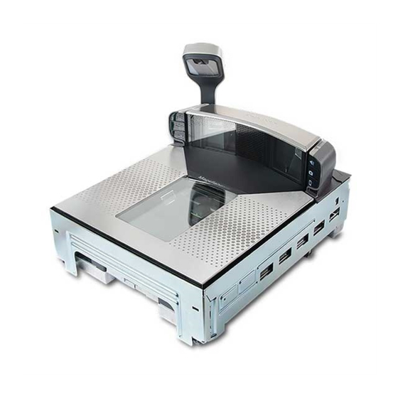
Page 16: Scanner Nomenclature
Introduction Scanner Nomenclature The parts and features of the scanner are shown in Figure 1. Control Panel buttons and indicators are described in more detail in Appendix A Optional features include the Scale (for weighing items) Top Down Reader (TDR) and Electronic Article Survel- lance (EAS). -
Page 17: Connectors And Ports
Connectors and Ports Connector port availability and appearance will differ between models, since these optional features may sometimes be added at the time of purchase. See the illustrations in Figure Figure 2 Figure ® • Checkpoint Electronic Article Survellance (EAS) Feature ®... - Page 18 Introduction Figure 3. Connector Panel POWER REMOTE DISPLAY USB PORTS HOST PORT · USB Handheld AC Brick Input Drives Remote Display · Label Data Scanner Input · Scale Data (for · USB-to-Serial adapter Power off Terminal single cable interfaces) used for scale cali- (POT) Brick Input ·...
-
Page 19: Physical Parameters
Physical Parameters This section provides specifications for performance, environmental and electrical parameters. Reference the second section of this manual, Site Preparation and Installation, for physical measurements of all models and some accessories. Scanning A scan zone (Figure 4) exists in the area between the horizontal and vertical scan windows, and the Top Down Reader (TDR), if that optional feature is present. -
Page 20: Weighing
Introduction Weighing Specifications for scale capacity, settling time, minimum and maximum static weight, zeroing, and warm-up time are given below. For more information regarding the topic: Proper Weighing Technique, refer to the Operation and Maintenance section of this manual. Rated Weight Capacity The scale’s operational weight capacity is: •... -
Page 21: Warm-Up Time
(2,152 LUX) Humidity Hot / Wet 40°C / 95% RH Hot / Dry 40°C / 5% RH Spill Proof (Datalogic MS-0006-13-0004) Cold / Dry 10°C / 5% RH Warm / Wet 25%C / 50% RH Storage +70° C +158° F -40°... -
Page 22: Electrical Specifications
Introduction Electrical Specifications Before installation, always verify that the site’s electrical service meets the scanner’s requirements. The scanner has been engineered for compatibility with most international electrical systems operating in ranges from 100 to 240VAC at 50-60 Hz. Verify that the power source will supply “clean”... -
Page 23: Safety Precautions
Safety Precautions No adjustments or alteration of the scanner or scanning-scale housing are to be attempted by the user. CAUTION This equipment has been tested and found to comply with the limits for a Class A digital device, pursuant to part 15 of the FCC Rules. These lim- its are designed to provide reasonable protection against harmful inter- ference when the equipment is operated in a commercial environment. -
Page 24: Labeling
Introduction Labeling Regulatory, reference and safety labeling is shown in Figure Figure 6. Labeling 0.00 SCALE HOST REMOTE POWER HOST PORT DISPLAY HOST SCALE 0.00 REMOTE POWER DISPLAY PORT HOST Beneath the Platter Underside of Scanner Scale Regulatory Label (units with scales Regulatory - I/F Label only) Serial Number Label... -
Page 25: Agency Compliances
Agency Compliances The scanner and scanning-scale meets or exceeds the requirements for its device type as set forth by the following agencies and regulations: COUNTRY COMPLIANCE COMMENTS Safety United States UL60950-1 cULus Approved Canada CAN/CSA C22.2 No. 60950-1 cULus Approved World IEC60950 CB certification... - Page 26 Safety CNS 14336-1 and EMC Taiwan BSMI CNS 13438 China Safety and EMC Argentina IRAM S mark Safety South Africa SABS Safety Contact Datalogic ADC, Inc. or your Datalogic representative for a complete listing of approvals for other countries. Magellan™ 9800i Scanner...
-
Page 27: Bar Codes Supported
Bar Codes Supported The scanner can read/decode the following 1D and 2D bar code types (symbologies): 1D Symbologies • UPC Versions A & E • Plural Stage Dual UPC Bar Codes for Japan ( 2 label read) • GSI DataBar Omnidirectional, DataBar Expanded, DataBar Stacked •... -
Page 28: Technical Support
Telephone Technical Support If you do not have internet or email access, you may contact Datalogic technical support at (541) 349-8283 or check the back cover of your manual for more contact information. Magellan™ 9800i Scanner... -
Page 29: Chapter 2. Site Preparation And Installation
Chapter 2 Site Preparation and Installation This section provides instructions on preparation of the checkstand for scanner or scanning- scale installation. It also specifies physical parameters, power and ventilation considerations, cable routing information and unit installation. Checkstand Preparation The guidelines that follow, titled , present specifics for models available at the time of this writing. -
Page 30: Installing The Optional Tdr
Site Preparation and Installation Figure 8. Scanner and Scanner/Scale Models Model 9801 Short Scanner Model 9803 Medium Scanner Model 9805 Long Scanner Model 9804 Model 9806 Medium Long Scanner/Scale Scanner/Scale Installing the Optional TDR Figure 8 Depending upon the model (see ), steps to install will vary slightly. - Page 31 Figure 9 6. Route the TDR cable down through the base of the scanner ( , #6), gently pulling it all the way through on the bulkhead side of the base and seating the TDR in its corner cavity. Make sure it is not pinched or caught beneath the scanner base. Use a 3mm ball end hex driver to secure the TDR with the two bolts provided for this Figure 9...
-
Page 32: Pre-Installation Considerations
Site Preparation and Installation Pre-Installation Considerations This manual does not cover all factors relating to worker safety and checkstand design. It does, however, offer a list of considerations that may be helpful in ensuring greater safety and productivity. Careful planning using these general guidelines should result in a more efficient, comfortable work environment. -
Page 33: Checkstand Design Recommendations
Checkstand Design Recommendations 1. Select a design which allows load-sharing by several muscle groups (for example designs which allow the cashier to use both hands for scanning and bagging). 2. Use a powered in-feed conveyor to help cashiers bring the items to their best work zone, rather than leaning and reaching to get items further up the conveyor. -
Page 34: Scanner Installation
Site Preparation and Installation Scanner Installation 1. Mount the horizontal surface of the scanner flush with the countertop to encourage slide scanning rather than lifting. 2. Position the centerline of the scanner read area 8 - 10 inches (20.3 - 25.4 cm) from the edge of the checkstand (cashier side). -
Page 35: Site Preparation Overview
Site Preparation Overview Consider the following factors before installing the scanner/scanning-scale and its optional Remote Scale Display. Ventilation Requirements — The scanner operates without the use of a ventilation fan. As long as there is adequate convective air flow and no major heat producing equipment in close proximity, the unit’s housing provides adequate heat dissipation. - Page 36 Site Preparation and Installation Figure 10. Vertical Clearance DO NOT DO NOT Obstruct Obstruct L-Platter Scan Zone Removal (Keyboard Mount) Allow a minimum clearance of 1.5" (3.8cm) (Enclosure) Magellan™ 9800i Scanner...
- Page 37 Display Clearance — Clearance must be allowed so that a POS display will not interfere with the scanner’s read zones. Adjustment must be made depending upon whether or not there is a Top Down Reader (TDR) installed. NO TDR — POS display placement for scanners not having a TDR must not encroach the scan zone formed by the horizontal and vertical windows.
-
Page 38: Ventilation And Spacing
Site Preparation and Installation Ventilation and Spacing The scanning-scale’s perimeter housing has been designed to provide adequate space for Figure 13 convective cooling and unrestricted movement of the weighing apparatus. shows the debris chutes and ventilation slots. The checkstand design must... •... -
Page 39: Power Installation
Power Installation Plug your scanner into an electrical outlet that has been wired to meet all applicable electrical codes, laws, and regulations and has a common ground with the Point-of-Sale terminal. Grounding The AC/DC Power Supply should have an AC outlet with a clean earth ground. If you are not sure how to verify the amount of electrical noise (interference) on the power line, ask a qualified electrician to measure the input line voltage. -
Page 40: Counter Cutout
Site Preparation and Installation Counter Cutout The most important consideration when planning the counter opening for the scanner is the operator’s comfortable reaching distance. The ideal, ergonomically sound installation allows items to be directed within easy reach, and a scanning area requiring no lifting or special orientation of items. - Page 41 Figure 15. Typical Checkstand Design & Cutout Location Conveyor Top Down Reader (TDR) (optional) Remote Display Bagging Area POS Terminal and Printer Bag Well Keyboard Check Writing Stand (optional) Scanner or Scanning-Scale Item Diverter (optional) Product Reference Guide...
- Page 42 Site Preparation and Installation Figure 16. Mounting the Scanner Flush Scanner Mounted Flush — Correct Scanner Mounted Scanner Mounted Below Flush — Incorrect Above Flush — Incorrect Refer to the appropriate drawing for cut-out and dimensional information on the model you’ll be installing: Cutout Reference...
- Page 43 Figure 17. Model 9801 (Short Scanner Model) Cutout Dimensions Model 9801 (Short) Max. Radius = 0.635cm Minimum Cutout (0.25") 4x Dimensions 35.6cm (14.00") min. 29.53cm (11.625") min. Model 9801 (Short) 10.36cm (4.08") Supports Liquid Drainage Liquid Drainage Support Rails Figure 18. Model 9801 (Short Scanner Model) Reference Dimensions 9.46cm (3.72”) Window 6.9cm (2.72”)
- Page 44 Site Preparation and Installation Figure 19. Models 9803 and 9804 (Medium Scanner or Scanning-Scale) Cutout Dimensions Models 9803 and 9804 (Medium Shelf) Minimum Cutout Dimensions Max. Radius = 0.25" (0.635cm) 15.825" (40.2cm) min. 11.625" (29.53cm) min. Models 9803 and 9804 (Medium Shelf) Supports (4.08") 10.36cm...
-
Page 45: Product Reference Guide
Figure 21 . Models 9805 and 9806 Long Scanner or Scanning-Scale Reference Dimensions Model 9805 51.12cm & Model 9806 (20.125") Max. Radius = 0.635cm 47.308cm Rail (0.25") 4x Cutout (18.625") 7.77 ±0.15 cm (3.06" ± .006") 1.905cm 29.53cm (0.75") (11.625") (Center Line) Rail 1.905cm... -
Page 46: Checkstand Mounting
Site Preparation and Installation Checkstand Mounting There are a number of things to take into account when installing the unit into a checkstand. Key factors are ergonomic/worker safety, loading capacity and stability. Don’t forget to add the scanner or scanning-scale’s weight when calculating materials and supports needed to construct a sturdy installation, as well as maximum capacity of weighed and scanned items. -
Page 47: Unpacking
Unpacking To unpack the unit: • Inspect the package for signs of damage that may have occurred during shipping. If dam- age is found, report it to your carrier immediately. • Lift out the accessory box containing the AC/DC Power Supply, optional Remote Scale Display and cable (if present), and the Quick Reference Guide. -
Page 48: Operational Verification
Site Preparation and Installation Operational Verification Follow these steps to ensure that your unit has arrived undamaged and is fully functional before installing it in the counter and connecting it to your POS system. 1. If the unit is a scanning-scale, connect the Remote Scale Display to the proper connector Figure 28 on the unit’s connector panel (refer to if the Remote Scale Display is not connected, a scanner power-up Selftest will... - Page 49 • Additionally, the Health & Status Indicator will flash the number ‘9’, indicating the EAS system is being initialized. If the Selftest detects a problem, the Health & Status Indicator will display a num- Chapter 5. Problem Isolation, for a description of failure ber code.
-
Page 50: Diagnostic Modes
Site Preparation and Installation • Hybrid Mode — In Hybrid Mode, the scanner must be enabled, however EAS deactiva- tion in this mode also takes place without needing to scan an item’s bar code. Pass an active EAS tag over the scanner in the same direction you would scan a bar code. The bot- tom-most LED will flash red, then orange, then return to green. -
Page 51: Scale Diagnostic Mode
To exit Scanner Diagnostic Mode, cycle power to the unit or press and hold the Scanner Scanner and Scale Reset Control Button for ten seconds to reset the scanner. See the topic, Chapter 3 for more information about unit resets. Scale Diagnostic Mode Pro- The scanner must be configured to allow Scale Diagnostic Mode. -
Page 52: Cables & Connections
Site Preparation and Installation Optional Remote Display Scale Diagnostics Indications If your unit is equipped with an optional Remote Display, it will show the following sequence, with each character being separated by a500ms or greater blank time on the display (for ease of reading). - Page 53 Figure 25. Cable Routing POS Terminal, Printer & Remote Cash Drawer Top Down Display Keyboard Reader (TDR) Scanner (Models vary) AC Power Switch Remote Scale (recommended) Display Cable Scanner (optional Interface AC/DC Scanner/Scale) Cable Power Supply Scale Sensormatic EAS Interface Models ONLY Cable EAS Antenna Cable...
-
Page 54: Remote Scale Display Placement/Installation
Site Preparation and Installation Remote Scale Display Placement/Installation When installing the optional Remote Scale Display, consider both the customer’s viewing angle Figure 27 and the amount of daily ambient light conditions anticipated at this installation site. shows available adjustment for the display head. Lighting Considerations The display(s) will be easily readable unless placed in direct sunlight or other very strong light sources. -
Page 55: Remote Display Cabling
Remote Display Cabling Your installation should also take into account the routing of Remote Display cabling. Ensure that distance and obstacles spanned by the routed cable will not kink, pinch or stretch it. Also keep in mind you may need to drill a hole through which to route it. The Remote Scale Display connector end may be secured with a rubber band during shipping to prevent damage to the “locking tabs”. - Page 56 Site Preparation and Installation 5. Feed the entire length of the Remote Scale Display interface cable through the cable rout- ing hole so that the assembled Remote Scale Display can be positioned over the mounting screw holes. 6. If present, remove the rubber band from the connector end. 7.
-
Page 57: Changing Weighing Modes
Changing Weighing Modes Your scanning-scale has been programmed for weighing in either pounds or kilograms depending upon the initial operating environment that was specified when you ordered your Technical scanning-scale. If you need to change from pounds to kilograms or vice-versa, call Support You can verify that the scale is set correctly for your country’s requirements by observing that the Remote Scale Display shows the appropriate measurement symbol (lb or kg) when the... - Page 58 Site Preparation and Installation Figure 31. Connecting Cables to the Scanner/Scale POWER REMOTE DISPLAY USB PORTS HOST PORT · USB Handheld AC Brick Input Drives Remote Display · Label Data Scanner Input · Scale Data (for · USB-to-Serial adapter Power off Terminal single cable interfaces) used for scale cali- (POT) Brick Input...
- Page 59 Figure 32. Optional EAS Cable Connections To Sensormatic ® ® To Checkpoint EAS System EAS System 5. Make sure that all cables are firmly attached (except that the AC/DC power supply should not be connected to the AC outlet yet). 6.
- Page 60 Site Preparation and Installation Figure 34. Using the Lift Handles Bubble Level 8. Lower the unit into the counter opening, ensuring that none of the cables are pinched, pierced or crimped. 9. View the bubble level (if present ) located on the scanner's spider assembly to ensure the Figure 33 scanner is level.
-
Page 61: System Power-Up Recap
System Power-Up Recap The System Power-Up procedure may vary depending upon the requirements of your POS system. It is generally a good practice to power-down (switch off) all equipment prior to connecting cables. Check with your System Supervisor and/or refer to your POS terminal manual for proper power-down and power-up procedures and interface requirements when connecting any peripheral device. - Page 62 Site Preparation and Installation NOTES Magellan™ 9800i Scanner...
-
Page 63: Chapter 3. Operation And Maintenance
Chapter 3 Operation and Maintenance The information contained in this section describes how to operate and maintain the scanner, scale and EAS system. Topics include “how to’s” on scanning, EAS tag deactivation, weighing, re-zeroing the scale, removing the top cover and cleaning the upper and lower windows. Scanning Items Figure 35 Figure 4... -
Page 64: Proper Weighing Technique (Scale Models)
Operation and Maintenance Proper Scanning Technique The scanner was designed to provide the ultimate in ergonomic enhancements for Point-Of- Sale (POS) scanning. To take advantage of these advancements: Practice the techniques below to improve scanning efficiency: Figure 35 • Move the product across the horizontal window (See •... -
Page 65: Deactivating Security Labels
Using the Optional ScaleSentry Feature If the scanning-scale has been equipped with ScaleSentry , infrared (IR) beam(s) are emitted Figure 36 along one or both long edges of the platter (See b). During the process when items are being weighed, if an item approaches too closely or extends past the edges of the weighing surface, this is detected by the IR beam(s) and the scanner will indicate a ScaleSentry event by illuminating its ScaleSentry indicator LED and/or sounding a special ScaleSentry tone. -
Page 66: Operational Controls
Operation and Maintenance deactivation status. (For more information about Beeper and LED indications, see the LED/ Beeper Indications & Controls section of this manual. Also reference the programming section for their configurable features.) By general default, LED indications are: • Green means the system is ready (standing by). -
Page 67: Operating Mode
Power-Up/Selftest Power-Up Selftest begins when power is applied. The scanner’s software immediately begins the testing sequence to verify that all systems are functioning properly. This routine, which only takes a few seconds, checks all the functions of the scanner, EAS deactivation system, scale, remote scale display and interface prior to indicating that it is ready for operation. -
Page 68: Additional Functions
Operation and Maintenance Normal Operation This condition is indicated by the scanner green LED and the EAS deactivation LED both being on dim and steady. For scanner/scale models, the scale yellow LED indicates that the scale senses a weight of zero on the platter. If you have a scanner without scale model, the yellow lamp will not be lit when the scanner is ready for scanning. -
Page 69: Scale Adjustments
terminal has been switched off or the store system has been reset while the unit is on. Reset can also be used to initiate and run the unit’s internal Selftest routine. Pressing and holding the Scanner Control Button for ten seconds initiates a reset, which is Power-Up/Selftest &... -
Page 70: Operational Maintenance
Operation and Maintenance inoperable until it has been recertified and a new seal attached. Consult your local regulations before removing the calibration seal if you are unsure of the legal requirements. Although the scale will physically continue to weigh products, a broken seal may require recertification by a proper authority as designated by your local laws. - Page 71 Figure 38 3. Either vertical window can be pressed out of its frame as shown in #3 of . Care- Figure 38 fully dispose of any damaged glass (#4 of Figure 38. Vertical Scan Window Removal/Replacement Push in to release 6 tabs Press window(s) in or out of the frame Lift off the wedge-shaped plastic Carefully dispose of the damaged glass...
-
Page 72: Horizontal Scan Window Replacement (Dlc)
Operation and Maintenance Horizontal Scan Window Replacement (DLC) Diamond-Like Carbon coated (DLC) horizontal scan windows are replaceable. Use the instructions below to remove and replace the window. Sapphire glass does not require replacement, so it is permanently fastened in place. Do not attempt to remove Sapphire glass from the platter. NOTE Figure 37 1. -
Page 73: Chapter 4. Tdr, Camera And Mobile Commerce
Chapter 4 TDR, Camera and Mobile Commerce The scanner can optionally include a Top Down Reader (TDR), Camera and/or a Mobile Commerce Reader. These premium features offer state-of-the-art functionality to point of sale transactions, while increasing first pass read rates for item scanning. Optional TDR Feature The Top Down Reader adds sixth side scanning to an already extensive scan zone (see Figure... -
Page 74: Camera Feature
TDR, Camera and Mobile Commerce Camera Feature In addition to scanning bar codes, the TDR can optionally be used to photograph images presented to the down-facing TDR window. The sales associate presses the scanner’s Camera button to initiate Camera Mode and take pictures. The way in which the TDR takes pictures in Camera Mode is a configurable feature. -
Page 75: Chapter 5. Problem Isolation
Chapter 5 Problem Isolation The troubleshooting references provided in this section should be used in the event of a suspected functional problem. This information will assist you in identifying and resolving any problems. The scanner/scale has a number of features that indicate when a scanner, EAS deactivation system, or scale problem occurs. -
Page 76: Diagnostic Procedures
Problem Isolation Diagnostic Procedures Your Point-Of-Sale (POS) system may contain many components that operate as a system. Since almost all scanner or scale problems are caused by either the scanner, scale, POS terminal or communication links between them, these troubleshooting flowcharts focus on these components. - Page 77 Table 6 describes what the FRU indication codes in step 2 mean, and what corrective action might be taken for each. Figure 43. Health & Status Indicator When troubleshooting, always remember to check all cable connec- tions first before proceeding with other problem isolation steps. NOTE Table 6.
- Page 78 Problem Isolation Health & Probable Cause Corrective Action Status Indicator Scale Error Reporting See the topic in this section for problem identifica- Scale tion and corrective actions. Connect the Remote Display. If necessary, replace display or cable. Alterna- Remote Display tively, you can disable the Remote Display using the programming proce- Chapter 7, Programming.
-
Page 79: Scale Error Reporting
Scale Error Reporting Scale diagnostics uses the optional Remote Scale Display and the Zero Status lamp to communicate specific scale failures. This does not apply to Adaptive Scale models. The following chart shows the Remote Display messages, the Scale Status lamp indication, the problem that the scale is experiencing and what action should be taken. -
Page 80: Flowcharts
Problem Isolation Flowcharts The problem isolation flowcharts on the following pages allow you to identify and troubleshoot problems with your system. Figure 44. Problem Isolation: Start For units using an AC/DC adapter, verify that... 1. AC power cord is connected to a functional AC outlet. 2. -
Page 81: Product Reference Guide
Figure 45. Problem Isolation: Selftest SELFTEST START Scan the Factory Does the Does the Does the Defaults bar code in Health & Status Health & Status Health & Status Section 6 to enable the Indicator show Indicator show Indicator show default configuration file. -
Page 82: Problem Isolation
Problem Isolation Figure 46. Problem Isolation: Poor/No Reading Have you verified that all scan windows are clean and scratch-free? POOR/NO READING Before proceeding, verify that START bar code samples presented to scanner are of good quality and a symbology the scanner Enter Scanner Diagnostic Mode by is configured to read. - Page 83 Figure 47. Problem Isolation: No Transmit to POS NO TRANSMIT TO POS START Check the interface (I/F) Verify programmable cable connections. If parameters using the possible, retest the Does the information and programming system using a scanner pass bar codes provided in the DONE known-good I/F cable.
- Page 84 Problem Isolation Figure 48. Problem Isolation: Scale If this is a new installation, SCALE START make sure any foam packing pieces have been removed from the scale cavity before proceeding. Lift off the platter View the Remote to verify, then set the platter Call Tech Support Display and/or the back into position.
- Page 85 Figure 49. Problem Isolation: Remote Display REMOTE DISPLAY Scanner-scale models that include START a Remote Display when shipped from the factory, are configured for use with the display. If you're unsure of the settings for your unit, contact Tech Support. Is the Use the programming bar unit configured...
- Page 86 Problem Isolation Figure 50. Problem Isolation: EAS System NO EAS DEACTIVATION Ensure operator has been trained in START proper EAS system use (reference the topic “Deactivating Security Labels”). Verify programmable Check all EAS parameters using the Does the If possible, retest the cable connections.
-
Page 87: Chapter 6. Calibration Procedures
Chapter 6 Calibration Procedures This section applies to scanner/scale models with single or dual interval. Make sure to follow the proper associated procedure for each of these options. Procedures specific to single interval units is highlighted in a salmon color. Procedures specific to dual interval units is highlighted teal... -
Page 88: Description Of Calibration Sequence
Calibration Procedures Description of Calibration Sequence The Calibration Sequence sets the scale to an accurate reference point for weighing. This process involves the use of a Field Standard Weight Set (31.5-pounds) for calibration in pounds, (18.5-kilograms) for Metric calibration. Once calibration has been successfully completed, the scanner/scale uses the certified weight as a reference for subsequent weighing activities. -
Page 89: Automatic Zero Setting Test
Automatic Zero Setting Test This test verifies that the scanner/scale automatic zero setting mechanism is operating correctly. SINGLE INTERVAL DUAL INTERVAL Place 0.006 pounds (3 grams for metric) on the Place 0.0035 pounds (1.6 grams for metric) on the center of the weighing platform. The entire center of the weighing platform. -
Page 90: Calibrating The Scale (Pounds & Kilograms)
Calibration Procedures Calibrating the Scale (Pounds & Kilograms) 1. Before proceeding, ensure that the scanner/scale has been prepared for this process by performing the preceding steps titled, Preparing the Scanner/Scale for Calibration 2. Verify that there are no obstructions under the weigh platter. Remove the weigh platter (L-Platter) and make sure that there are no obstructions in the debris chutes (see Figure 13). - Page 91 You have completed the scale calibration procedure. Before replacing the Calibration Switch Cover and sealing the scale, you must now continue with the calibration verification tests to complete the scale’s calibration. If you are weighing in pounds, continue with the following procedures to verify that the scale was successfully calibrated and that it weighs properly.
-
Page 92: Calibration Verification (Pounds)
Calibration Procedures Calibration Verification (Pounds) Once you have completed the calibration sequence, you may be required to perform these step-by-step verification procedures. These procedures follow the National Institute of Standards and Technology Handbook-44 guidelines for grocery scale installations. You may be required by state or local law to have these procedures performed by a certified technician or verified by a proper official. - Page 93 Shift Test (6 Pounds Dual Interval ONLY) The Shift Test checks to ensure that items placed anywhere on the weighing surface of the scanner/scale are weighed properly. Refer to Figure 53 when performing this test. DUAL INTERVAL 1. Place and remove, in succession, a six-pound load on the center of each of the four quadrants: 1, 2, 3, and 4, (as shown in Figure...
- Page 94 Calibration Procedures Increasing- Load Test (Phase 2 Dual Interval) The upper limit of the scale is configurable according to the POS interface type and may not necessarily be set at 30 pounds, which is the standard setting. For this test, continue to place weights in two pound increments only up to the upper weight limit set for your scale.
-
Page 95: Blanking Test
Increasing- Load Test (Single Interval Phase 2) (Dual Interval Phase 3) After completing the Shift Test, you must complete the Increasing Load Test using 20.0, 25.0 and 30.0 pounds of weight. The upper limit of the scale is configurable according to the POS interface type and may not necessarily be set at 30 pounds, which is the standard setting. -
Page 96: Return To Zero Test
Calibration Procedures Decreasing-Load Test This test ensures that the scanner/scale responds properly when a heavy object is followed by a significantly smaller object. If the upper weight limit for your scale is set to other than 30 pounds, begin by placing weight equaling your upper limit set- ting. -
Page 97: Calibration Verification (Kilograms)
Calibration Verification (Kilograms) Once you have completed the calibration sequence, you may be required to perform these step-by-step verification procedures. These procedures follow the National Institute of Standards and Technology Handbook-44 guidelines for grocery scale installations. You may be required by state or local law to have these procedures performed by a certified technician or verified by a proper official. - Page 98 Calibration Procedures Shift Test Metric (2 Kilogram Dual Interval ONLY) The Shift Test checks to ensure that items placed anywhere on the weighing surface of the Figure 54 scanner/scale are weighed properly. Refer to when performing this test. DUAL INTERVAL 1.
- Page 99 Increasing Load Test (Phase 2 Dual Interval ONLY) After completing the Shift Test, you must complete the Increasing Load Test using 4, 5 and 6 kilograms of weight. The upper limit of the scale is configurable according to POS interface type and may not necessarily be set at 15 kilograms, which is the standard setting.
- Page 100 Calibration Procedures Increasing- Load Test (Single Interval Phase 2) (Dual Interval Phase 3) The upper limit of the scale is configurable according to POS interface type and may not necessarily be set at 15 kilograms, which is the standard setting. For this test, continue to place weights in 2.50 kilograms increments only to the upper weight limit set for your scale.
- Page 101 Decreasing-Load Test This test ensures that the scanner/scale responds properly when a heavy object is followed by a significantly smaller object. If the upper weight limit for your scale is not set at 15 kilograms, begin by placing weight equaling your upper limit plus 0.8 kilograms.
- Page 102 Calibration Procedures NOTES Magellan™ 9800i Scanner...
-
Page 103: Chapter 7 Programming
Chapter 7 Programming Introduction to Label Programming The programming bar code labels contained in this manual will allow you to customize and configure features and settings for your scanner (scanner/scale). To ensure full compatibility and proper function, use only the programming bar codes in this manual and other product- specific publications to program scanner features. -
Page 104: Bar Code Mask
Programming Bar Code Mask Cut a hole in this page and remove it from the manual as indicated to create a sleeve through which bar codes (starting in the following section) can be individually viewed and scanned. It is important that only one bar code at a time be presented to the scanner. 1. -
Page 105: Integrating The Scanner With Your Host System
Integrating the Scanner With Your Host System Your scanner MUST be equipped with the correct hardware (interface board, cable, etc.) to properly communicate with your host system. Contact your dealer for information if you have questions about your scanner’s hardware compatibility. You may also want to contact the dealer or your system administrator if you have no record of how your scanner was pre-programmed at the factory. -
Page 106: Programming Overview
Eligible handheld devices must have the ability to transmit the C128 1D and Data Matrix 2D programming bar codes presented in this manual. Several Datalogic handheld models support this functionality. Handheld data format requirements (baud rate, parity, etc.) are presented in Appendix G of this manual. -
Page 107: Programming Session
Programming Session A typical programming session is conducted as follows: 1. Scan the Enter/Exit Programming Mode bar code to place the scanner in Programming Mode. Depending upon its current programming, the scanner may emit a beep or beeps, indicating it has read the bar code and the green LED will flash on and off slowly while the scanner remains in Programming Mode. -
Page 108: Programming Sequence
Programming —power is disconnected. Disconnecting power during Programming Mode, before scanning the Enter/Exit Programming Mode bar code, will cause all new settings to be ignored . On power-up, the scanner will return to previous settings. 4. Maintain a good record of all changes made to ensure that you know if the original fac- tory settings have been changed. - Page 109 Table 8. Programming Sequence ITEM TAG ITEM VALUE END/RESET Enter/Exit Enter/Exit ENABLE Programming Programming NEW FEATURE Mode Mode 3 4 5 ENABLE NEW FEATURE USING THE Enter/Exit Enter/Exit FOLLOWING Programming Programming SETTINGS... Mode Mode ONE BAR CODE CONTAINS ENTER + ITEM TAG + ITEM VALUE + EXIT Product Reference Guide...
-
Page 110: Led And Beeper Indicators
Programming LED and Beeper Indicators The scanner provides a set of indicators that verify/announce the various scanner functions. Appendix A for more details. If You Make a Mistake... If, during a programming session, you find that you are unsure of the scanner’s settings or wish to reset the scanner’s configuration, use the Return to Factory Settings label below to return the scanner’s configuration to the factory settings. -
Page 111: Test Mode
Test Mode Use this feature to place the scanner into a testing, or “demo” mode. This special mode disables the scanner interface, meaning that bar code data is not sent out to the host via the scanner interface. This allows the bar code to be scanned continuously without requiring a response from the POS terminal. - Page 112 Programming NOTES Magellan™ 9800i Scanner...
-
Page 113: Chapter 8. Imaging Features
Chapter 8 Imaging Features Top Down Reader (TDR) and Mobile Commerce Imaging Features The TDR and its multiple capabilities are optional features with which your scanner may equipped. The imaging features in this chapter pertain only to the TDR and Mobile Figure 55, #1 illustrates the TDR’s top down reading capability and #2 Commerce reader. -
Page 114: Mobile Commerce Reader Enable
Enter/Exit Programming Mode Mobile Commerce Reader Enable The Mobile Commerce reader is an optional customer-facing imager (see Figure 55, #2) which captures images such as coupons from a cell phone screen. Use the bar codes below to enable or disable the Mobile Commerce reader. 1. -
Page 115: Mobile Commerce Imagers
Enter/Exit Programming Mode Mobile Commerce Imagers This feature specifies which imagers (see Figure participate in a cell read • Mobile Commerce only • Mobile Commerce and Top Down Reader (TDR) To set the desired option: 1. Scan the Enter/Exit Programming Mode bar code. 2. -
Page 116: Mobile Commerce Button Function
Enter/Exit Programming Mode Mobile Commerce Button Function This feature determines if pushing the Mobile Commerce button toggles the Mobile Commerce reader on and off, or just turns it on for a short period of time. 1. Scan the ENTER/EXIT Programming Mode bar code. 2. -
Page 117: Tdr Enable
Enter/Exit Programming Mode TDR Enable The Top Down Reader (TDR) function is an optional down-facing imager (see Figure #1) which can be used to expand the scanner’s good read zone. Use the bar codes below to enable or disable the TDR. 1. -
Page 118: Image Camera
Enter/Exit Programming Mode Image Camera This option selects the default imager for picture taking (optional camera functionality). Choices are: Vertical window imager selected for taking pictures. Vertical — Horizontal window imager selected for taking pictures. Horizontal — Top Down Reader (TDR) imager selected for taking pictures. TDR —... -
Page 119: Image Format
Enter/Exit Programming Mode Image Format This feature specifies the output format for images taken usinig the camera function of the TDR. Choices are: • • • TIFF 03E900(CR) DEFAULT Image Format = JPG 03E901(CR) Image Format = BMP 03E902(CR) Image Format = TIFF Product Reference Guide... -
Page 120: Image Size
Enter/Exit Programming Mode Image Size This feature specifies the size of the captured image. Choices are: Video Graphics Array. 640 x 480 pixels. VGA — Wide Video Graphics Array, various physical sizes, 16:9 shape WVGA — Maximum image height and width. Largest image. Full Size —... -
Page 121: Image Brightness
Enter/Exit Programming Mode Image Brightness Specifies the image brightness value. The selectable range is from 0 to 10, with 10 being the brightest. 03EB00(CR) DEFAULT Image Brightness = 0 03EB01(CR) Image Brightness = 1 03EB02(CR) Image Brightness = 2 03EB03(CR) Image Brightness = 3 03EB04(CR) Image Brightness = 4... - Page 122 Enter/Exit Programming Mode Image Brightness (continued) 03EB08(CR) Image Brightness = 8 03EB09(CR) Image Brightness = 9 03EB0A(CR) Image Brightness = 10 Magellan™ 9800i Scanner...
-
Page 123: Image Contrast
Enter/Exit Programming Mode Image Contrast This feature sets the contrast level for a captured image. The selectable range is from 0 to 10, with 0 being the lowest and 10 being the highest contrast. 03EC00(CR) DEFAULT Image Contrast = 0 03EC01(CR) Image Contrast = 1 03EC02(CR) - Page 124 Enter/Exit Programming Mode Image Contrast (continued) 03EC08(CR) Image Contrast = 8 03EC09(CR) Image Contrast = 9 03EC0A(CR) Image Contrast = 10 Magellan™ 9800i Scanner...
-
Page 125: Chapter 9. General Scanner And Scale Features
Enter/Exit Programming Mode Chapter 9 General Scanner and Scale Features 1D Double Read Timeout The 1D Double Read Timeout feature specifies the minimum allowable time which must pass before reading the same 1D label again (e.g. two identical items in succession). To set the Double Read Timeout: 1. -
Page 126: Double Read Timeout
Enter/Exit Programming Mode 2D Double Read Timeout The 2D Double Read Timeout feature specifies the minimum allowable time which must pass before reading the same 2D label again (e.g. two identical items in succession). To set this feature: 1. Scan the Enter/Exit Programming Mode bar code. 2. -
Page 127: Label Gone Timeout
Enter/Exit Programming Mode Label Gone Timeout Specifies the amount of time in cycles (one cycle = 25ms) that data segments are stored by the software before being discarded if a label has not been successfully decoded during the current “label in volume session,” which is defined as the time between when the label gone time is first started until the label gone timer expires. -
Page 128: Sleep Mode Timer
Enter/Exit Programming Mode 004C30(CR) Label Gone Timeout = 1.2 Seconds 004C40(CR) Label Gone Timeout = 1.6 Seconds Sleep Mode Timer This feature specifies the amount of time of inactivity (with no label reads) before the scanner enters sleep mode. To set this feature: 1. -
Page 129: Inverse Read Control
Enter/Exit Programming Mode 1D Inverse Read Control This configuration item is used to toggle inverted label reading for 1D bar codes, for example, a label printed as white on black as opposed to black on white. To set this feature: 1. -
Page 130: Inverse Read Control
Enter/Exit Programming Mode 2D Inverse Read Control This configuration item is used to toggle inverted label reading for 2D bar codes, for example, a label printed as white on black as opposed to black on white. To set this feature: 1. -
Page 131: Contrast Improvement
Enter/Exit Programming Mode 3. Complete the programming sequence by scanning the Enter/Exit Programming Mode bar code. 063A00(CR) DEFAULT Illumination Control = Disable 063A01(CR) Illumination Control = Enable 2D Contrast Improvement This feature enables / disables the scanner’s ability to enhance the image contrast for scanned 2D symbologies. -
Page 132: Good Read Led Idle State
Enter/Exit Programming Mode Good Read LED Idle State This feature specifies the state of the green scanner LEDs when the scanner is idle and ready to read a label. Options are: • • On dim To set the Scanner LEDs Idle State: 1. -
Page 133: Scanner Control Button Options
Enter/Exit Programming Mode Scanner Control Button Options Configure the Scanner Control Button to one of the following modes of operation: • Enable all functions: Volume, tone, diagnostics and reset. • Enable only volume, tone and reset. • Enable reset only. •... -
Page 134: Power-Up Tone Control
Enter/Exit Programming Mode Power-up Tone Control Specifies the type of audible indication that is made when entering scanner-active mode on power-up. Choices are: • No tone • Play tone To set the Power-up tone: 1. Scan the Enter/Exit Programming Mode bar code. 2. -
Page 135: Good Read Beep Control
Enter/Exit Programming Mode Good Read Beep Control This feature enables/disables scanner beep upon successfully decoding of a label. To set this feature: 1. Scan the Enter/Exit Programming Mode bar code. 2. Scan your selection from the bar codes below. You’ll need to cover any unused bar codes on this and the facing page to ensure that the scanner reads only the bar code you intend to scan. -
Page 136: Good Read Beep Frequency
Enter/Exit Programming Mode Good Read Beep Frequency Adjusts the scanner’s good read beep to sound at low, medium, or high frequency (controls the beeper’s pitch/tone). • • Medium • High To set this feature: 1. Scan the Enter/Exit Programming Mode bar code. 2. -
Page 137: Good Read Beep Length
Enter/Exit Programming Mode Good Read Beep Length Specifies the duration of a good read beep. To set this feature: 1. Scan the Enter/Exit Programming Mode bar code. Set Good Read Beep Length. You’ll need to cover any unused bar 2. Scan the bar code, codes on this and the facing page to ensure that the scanner reads only the bar code you intend to scan. -
Page 138: Good Read Beep Volume
Enter/Exit Programming Mode Good Read Beep Volume Selects the beeper volume upon a good read beep. There are five selectable volumes, with each volume increment adding approximately five decibels to the previous level: • • Medium High • Medium Low •... -
Page 139: Good Read When To Indicate
Enter/Exit Programming Mode Good Read When to Indicate This feature specifies when the scanner will provide indication (beep and/or flash its green LEDs) upon successfully reading a bar code. • Good Read = Indicate after decode • Good Read = Indicate after transmit •... -
Page 140: Scale Zero Button And Scale Indicator Led
Enter/Exit Programming Mode Scale Zero Button and Scale Indicator LED Here are the configurable options for the Scale Zero Button and Scale Indicator LED: • Scale Zero Button and Scale Indicator LED active • Scale Indicator LED active • Scale Zero Button active •... -
Page 141: Scale Sentry
Enter/Exit Programming Mode Scale Sentry This option enables or disables the ability of the scanner to monitor items placed on the platter Scale SentryTM to ensure they are not overhanging non-weighing surfaces. See the topic Option Introduction in the chapter for more information. To set this feature: 1. -
Page 142: Scale Sentry Block Weight Transmission
Enter/Exit Programming Mode Scale Sentry Block Weight Transmission This option enables or disables weight transmission to the host if a Scale Sentry event is active. When enabled, this feature blocks the transmission of weight data to the host if Scale Sentry has sensed an item or items overhanging the side(s) of the scale platter. -
Page 143: Scale Sentry Override Button
Enter/Exit Programming Mode Scale Sentry Override Button This option allows a press of the Scale Sentry Override Button to manually clear a Scale Sentry event. To set this feature: 1. Scan the ENTER/EXIT Programming Mode bar code. 2. Scan your selection from the bar codes below. You’ll need to cover any unused bar codes on this and the facing page to ensure that the scanner reads only the bar code you intend to scan. -
Page 144: Scale Enable
Enter/Exit Programming Mode Scale Enable Use this feature to enable or disable scale operation. Recalibration/recertification may be required when adding scale function- ality. Consult your local Weights and Measures authority. NOTE To set this feature: 1. Scan the Enter/Exit Programming Mode bar code. 2. -
Page 145: Scale Diagnostics Mode
Enter/Exit Programming Mode Scale Diagnostics Mode Use this feature to allow or disallow the ability of an operator to initiate the advanced feature, scale diagnostics. To set this feature: 1. Scan the Enter/Exit Programming Mode bar code. 2. Scan your selection from the bar codes below. You’ll need to cover any unused bar codes on this and the facing page to ensure that the scanner reads only the bar code you intend to scan. -
Page 146: Scale Stale Weight Timeout
Enter/Exit Programming Mode Scale Stale Weight Timeout This option specifies the amount of time that scale data is presented to the host before being dis- carded. To set this feature: 1. Scan the Enter/Exit Programming Mode bar code. Set Scale Stale Weight Timeout 2. -
Page 147: Scale Enforced Zero Return
Enter/Exit Programming Mode Scale Enforced Zero Return This feature sets the mode of enforcing the scale re-zeroing operation: • Disable • Non-zero for more than 4 minutes OR below zero • Non-zero for more than 4 minutes OR below zero OR no zero between weights To set this feature: 1. -
Page 148: Scale Interface Type
Enter/Exit Programming Mode Scale Interface Type Use this feature to select the scale interface type. Choices are:. • No scale interface • IBM 46XX (Port 17 ignored) • Mettler Toledo 8217 • USB (IBM ignored) • RS-232 - SASI • RS-232 - ICL •... - Page 149 Enter/Exit Programming Mode Scale Interface Type (continued) Remember to cover any unused bar codes on this and the facing page to ensure that the scanner reads only the bar code you intend to scan. 040404(CR) DEFAULT Scale Interface Type = RS-232 - SASI 040405(CR) Scale Interface Type = RS-232 - ICL 040406(CR)
-
Page 150: Scale Calibration Notification
Enter/Exit Programming Mode Scale Calibration Notification This option enables a notification that scale calibration has taken place. To set this feature: 1. Scan the Enter/Exit Programming Mode bar code. 2. Scan your selection from the bar codes below. You’ll need to cover any unused bar codes on this and the facing page to ensure that the scanner reads only the bar code you intend to scan. -
Page 151: Scale Intercharacter Delay
Enter/Exit Programming Mode Scale Intercharacter Delay With regard to scale functions, this feature specifies a delay between the end of one character and the beginning of the next in 10-millisecond increments. To set the Scale Intercharacter Delay: 1. Scan the Enter/Exit Programming Mode bar code. Set Scale Intercharacter Delay. -
Page 152: Remote Display - Enable/Disable
Enter/Exit Programming Mode Remote Display — Enable/Disable The scanning-scale can be configured to operate with or without a Remote Display. Recalibration/recertification may be required when adding a Remote Dis- play. Consult your local Weights and Measures authority. If this feature is enabled the scanner will expect that it is connected to a Error Codes Remote Display, and will indicate an error if one is not. -
Page 153: Auxiliary Port Mode
(only one option can be active at a time). • Disabled — Port is inactive • External Handheld Input — Supports Datalogic handheld scanners (QuickScan 1000, QuickScan 6000, PowerScan ) as well as other models such as the Symbol®... -
Page 154: Auxiliary Usb Mode
Enter/Exit Programming Mode Auxiliary USB Mode This option specifies the function of the USB auxiliary port. To set this feature: 1. Scan the Enter/Exit Programming Mode bar code. 2. Scan your selection from the bar codes below. You’ll need to cover any unused bar codes on this and the facing page to ensure that the scanner reads only the bar code you intend to scan. -
Page 155: Productivity Index Reporting (Pir) / Cashier Training (Ct)
Enter/Exit Programming Mode Productivity Index Reporting (PIR) / Cashier Training (CT) When PIR/CT is enabled, label quality data is appended to decoded data before being presented to the POS. The PIR feature allows the scanner to provide information to an external computer indicating how easy the label was to read. -
Page 156: Pir/Ct Auxiliary Port Baud Rate
Enter/Exit Programming Mode PIR/CT Auxiliary Port Baud Rate This feature specifies the baud rate of the auxiliary port when operating in PIR/CT Mode. Auxiliary Port Mode This setting is valid ONLY when is set to PIR/CT + Diagnostics Reporting. NOTE To set this feature: 1. - Page 157 Enter/Exit Programming Mode PIR/CT Auxiliary Port Baud Rate (continued) 051607(CR) PIR/CT Auxiliary Port Baud Rate = 57600 051608(CR) PIR/CT Auxiliary Port Baud Rate = 115200 Product Reference Guide...
- Page 158 Enter/Exit Programming Mode NOTES Magellan™ 9800i Scanner...
-
Page 159: Chapter 10. Eas Features
Chapter 10 EAS Features EAS Features — Sensormatic These features control the Sensormatic® AMB-9010 or ScanMaxPro EAS controller box. This orderable option is installed at the time of manufac- EAS Features — Checkpoint on page 160 ture. See to set options for the Checkpoint®... -
Page 160: Eas Mode
Enter/Exit Programming Mode EAS Mode ® This controls the mode of operation for interfacing with the Sensormatic AMB-9010 or ScanMaxPro EAS controller box. Choices are: • Disabled = EAS deactivation turned off. • Coupled Mode = EAS tag is deactivated only upon successful scanning of an item’s bar code or via EAS Exception Button. - Page 161 Enter/Exit Programming Mode EAS Mode (continued) Remember to cover any unused bar codes on this and the facing page to ensure that the scanner reads only the bar code you intend to scan. 058002(CR) EAS Mode = Decoupled Mode 058003(CR) EAS Mode = Hybrid Mode 058004(CR) EAS Mode = Host Coupled Mode...
-
Page 162: Eas Notification
Enter/Exit Programming Mode EAS Notification This feature specifies the output mode and activation of EAS event notification when operating in Coupled Mode. To set this feature: 1. Scan the Enter/Exit Programming Mode bar code. 2. Scan your selection from the bar codes below. You’ll need to cover any unused bar codes on this and the facing page to ensure that the scanner reads only the bar code you intend to scan. -
Page 163: Eas Security Level
Enter/Exit Programming Mode EAS Security Level This feature defines the level of EAS security for operating in coupled mode. To set this feature: 1. Scan the Enter/Exit Programming Mode bar code. 2. Scan your selection from the bar codes below. You’ll need to cover any unused bar codes on this and the facing page to ensure that the scanner reads only the bar code you intend to scan. -
Page 164: Eas Good Beep Mode
Enter/Exit Programming Mode EAS Good Beep Mode This feature sets the mode of operation for the EAS deactivation beep while operating in coupled mode. To set this feature: 1. Scan the Enter/Exit Programming Mode bar code. 2. Scan your selection from the bar codes below. You’ll need to cover any unused bar codes on this and the facing page to ensure that the scanner reads only the bar code you intend to scan. -
Page 165: Eas Beep Duration
Enter/Exit Programming Mode EAS Beep Duration Sets the duration of the EAS successful deactivation beep, specified in 10ms increments. The beep only occurs if EAS mode is not disabled. To set the EAS Beep Duration: 1. Scan the Enter/Exit Programming Mode bar code. 2. -
Page 166: Eas Retry Count
Enter/Exit Programming Mode EAS Retry Count This feature sets the number of times the deactivation sequence (defined by the feature, “EAS Deactivation Duration — Retry ”) is restarted after a failed deactivation attempt. To set this feature: 1. Scan the Enter/Exit Programming Mode bar code. 2. -
Page 167: Eas Exception Button
Enter/Exit Programming Mode EAS Exception Button This feature is for use in Coupled Mode . When it is enabled, EAS deactivation can be manually initiated by placing the item with the EAS tag downstream of the horizontal scan window and pushing the EAS Exception Push Button. The scanner emits a clicking sound while in deactivation state. -
Page 168: Eas Deactivation Duration - Coupled
Enter/Exit Programming Mode EAS Deactivation Duration — Coupled Specifies the amount of time EAS deactivation is operative once the function has been initiated following a bar code read. This setting pertains only to units configured for EAS Coupled Mode. Refer- EAS Mode ence the description for more information about Coupled and... -
Page 169: Eas Deactivation Duration - Retry
Enter/Exit Programming Mode EAS Deactivation Duration — Retry Specifies the amount of time EAS deactivation is operative once the function has been initiated following EAS tag detection (prior to bar code read). This setting pertains only to units configured for EAS Coupled Mode. Refer- EAS Mode ence the description for more information about Coupled and... -
Page 170: Eas Deactivation Duration - Exception
Enter/Exit Programming Mode EAS Deactivation Duration — Exception Specifies the amount of time EAS deactivation is operative upon pushing the EAS Exception Button. This setting pertains only to units configured for EAS Coupled Mode. Refer- EAS Mode ence the description for more information about Coupled and EAS Retry Count. -
Page 171: Eas Pre-Read Time
Enter/Exit Programming Mode EAS Pre-Read Time This feature specifies the time duration that must elapse before reading a label once an EAS tag is sensed. To set this feature: 1. Scan the Enter/Exit Programming Mode bar code. 2. Scan the bar code, Set EAS Pre-Read Time below. -
Page 172: Eas Features - Checkpoint
Enter/Exit Programming Mode EAS Features — Checkpoint ® The features in this section apply only to Checkpoint EAS systems. See EAS Features — Sensormatic on page 147 to set options for that system. ERI Active State Specifies the active state polarity of ERI; the inactive state is its opposite polarity. ERI output goes active during the good read of a bar code, allowing the EAS device to deactivate a tag on the product. -
Page 173: Eri Timeout
Enter/Exit Programming Mode ERI Timeout Specifies the amount of time that an ERI signal is held in its active state for a good read. To set the ERI Timeout: 1. Scan the Enter/Exit Programming Mode bar code. 2. Scan the bar code, Set ERI Timeout below. - Page 174 EAS Features NOTES Magellan™ 9800i Scanner...
-
Page 175: Chapter 11. Interface Related Features
Chapter 11 Interface Related Features Interface Type Specifies the current scanner interface. Selections are: I/F I.D. INTERFACE (I/F) TYPE NUMBER RS-232 Standard RS-232 Wincor-Nix- dorf RS-232 Single Cable USB OEM Port 17 Port 5B Port 9B USB Keyboard USB-TEC USB COM NOT USER-SELECTABLE 7-segment FRU display indi-... - Page 176 Interface Related Features A new scanner may have been shipped from the factory with a Null Inter- face (no interface type selected) to ensure system compatibility at installa- tion. In this case, the correct Interface Type programming bar code must be scanned first before the scanner can be used with a POS system.
-
Page 177: Interface Selection
Enter/Exit Programming Mode RS-232 Interface Selection Remember to cover any unused bar codes on this and the facing page to ensure that the scanner reads only the bar code you intend to scan. Great care should be taken to select the correct interface type, since you can cause damage to the scanner and/or POS terminal by attempting to change to an incompatible interface. -
Page 178: Usb Interface Selection
Enter/Exit Programming Mode USB Interface Selection Remember to cover any unused bar codes on this and the facing page to ensure that the scanner reads only the bar code you intend to scan. Great care should be taken to select the correct interface type, since you can cause damage to the scanner and/or POS terminal by attempting to change to an incompatible interface. -
Page 179: Ibm Interface Selection
Enter/Exit Programming Mode IBM Interface Selection Remember to cover any unused bar codes on this and the facing page to ensure that the scanner reads only the bar code you intend to scan. Great care should be taken to select the correct interface type, since you can cause damage to the scanner and/or POS terminal by attempting to change to an incompatible interface. -
Page 180: Keyboard Interface Selection
Enter/Exit Programming Mode Keyboard Interface Selection Remember to cover any unused bar codes on this and the facing page to ensure that the scanner reads only the bar code you intend to scan. Great care should be taken to select the correct interface type, since you can cause damage to the scanner and/or POS terminal by attempting to change to an incompatible interface. -
Page 181: Maximum Host-Transmitted Message Length
Enter/Exit Programming Mode Maximum Host-Transmitted Message Length Specifies the maximum number of data characters allowed in messages transmitted to the host. To set the Maximum Host-Transmitted Message Length: 1. Scan the Enter/Exit Programming Mode bar code. Set Maximum Host-Transmitted Message Length 2. -
Page 182: Ibm Features
Enter/Exit Programming Mode IBM Features IBM Interface Options IBM interfaces offer specific control over interaction with certain devices. The USB OEM interface provides its own set of options. Refer to the feature, USB OEM Interface Options, in this section. NOTE Options for this feature are as follows: •... -
Page 183: Ibm Scale Address
Enter/Exit Programming Mode IBM Scale Address This feature applies to IBM Port 17 ONLY. NOTE Specifies IBM scale address for IBM Port 17. The following three addresses are available: • • • To set the IBM Scale Address: 1. Scan the Enter/Exit Programming Mode bar code. 2. -
Page 184: Ibm Transmit Labels In Code 39 Format
Enter/Exit Programming Mode IBM Transmit Labels in Code 39 Format This feature enables/disables scanner's ability to set a symbology identifier for a specified label to Code 39 before transmitting that label data to an IBM host. This applies to: Code 128, Code 93 and Codabar for IBM Port 5B;... -
Page 185: 46Xx Number Of Host Resets
Enter/Exit Programming Mode 46XX Number of Host Resets This setting specifies the number of consecutive resets before entering label Programming Mode to allow scanner configuration. To set this feature: 1. Scan the Enter/Exit Programming Mode bar code. Set 46XX Number of Host Resets 2. -
Page 186: 46Xx Label Slicing Control
Enter/Exit Programming Mode 46XX Label Slicing Control This feature enables slicing of IBM 46XX host data into multiple pieces when a label is longer 46XX Maximum Label Slice Length than the length specified by the feature To set this feature: 1. -
Page 187: 46Xx Maximum Label Slice Length
Enter/Exit Programming Mode 46XX Maximum Label Slice Length This feature specifies the maximum allowable length of host transmitted data in each sdlc frame. 46XX Label Slicing Control This setting only applies when is enabled. NOTE To set this feature: 1. Scan the Enter/Exit Programming Mode bar code. Set 46XX Maximum Label Slice Length 2. -
Page 188: Usb Oem Interface Options
Enter/Exit Programming Mode USB OEM Interface Options The OEM-USB interface offers specific control over interaction with certain devices. Options for this feature are as follows: • FULL host interface support — Accepts scanner and scale configuration host commands. • Compatible with Magellan SL host interface support — Uses Magellan SL host interface support. -
Page 189: Usb Oem Scanner Device Type
Enter/Exit Programming Mode USB OEM Scanner Device Type The OEM-USB protocol allows for the scanner to be identified as one of two different types of bar code scanners. Depending on what other scanners you may already have connected to a USB POS, you may need to change this setting to enable all scanners to communicate. -
Page 190: Features
Enter/Exit Programming Mode RS-232 Features RS-232 Baud Rate This feature selects the baud rate required for sending and receiving data. Single cable interfaces are limited to Baud Rate selections up to 19200. They cannot communicate at Baud Rates of 38400 and up. NOTE To specify the RS-232 Baud Rate: 1. - Page 191 Enter/Exit Programming Mode RS-232 Baud Rate (continued) 001D06(CR) RS-232 Baud Rate = 38400 001D07(CR) RS-232 Baud Rate = 57600 001D08(CR) RS-232 Baud Rate = 115200 001D09(CR) RS-232 Baud Rate = 230400 001D0A(CR) RS-232 Baud Rate = 460800 001D0B(CR) RS-232 Baud Rate = 921600 Product Reference Guide...
-
Page 192: Number Of Data Bits
Enter/Exit Programming Mode RS-232 Number of Data Bits Specifies number of data bits required for sending and receiving data. To set this feature: 1. Scan the Enter/Exit Programming Mode bar code. 2. Scan the bar code below representing the desired Data Bit setting. You’ll need to cover any unused bar codes on this and the facing page to ensure that the scanner reads only the bar code you intend to scan. -
Page 193: Number Of Stop Bits
Enter/Exit Programming Mode RS-232 Number of Stop Bits Specifies number of stop bits required for sending and receiving data. To set this feature: 1. Scan the Enter/Exit Programming Mode bar code. 2. Scan the bar code below representing the desired Stop Bit setting. You’ll need to cover any unused barc odes on this and the facing page to ensure that the scanner reads only the bar code you intend to scan. -
Page 194: Parity
Enter/Exit Programming Mode RS-232 Parity Specifies parity required for sending and receiving data. Options for this setting are: • RS-232 PARITY = NONE • RS-232 PARITY = EVEN • RS-232 PARITY = ODD To set this feature: 1. Scan the Enter/Exit Programming Mode bar code. 2. -
Page 195: Hardware Control
Enter/Exit Programming Mode RS-232 Hardware Control Enables/disables use of the RS-232 CTS signal for flow control and/or scan control. Options are: • Disable — The scanner transmits to the host regardless of any activity on the CTS line. • Enable CTS Flow Control — The CTS signal controls transmission of data to the host. •... -
Page 196: Intercharacter Delay
Enter/Exit Programming Mode RS-232 Intercharacter Delay Specifies delay between the end of one character and the beginning of the next in 10- millisecond increments. To set the RS-232 Intercharacter Delay: 1. Scan the Enter/Exit Programming Mode bar code. Set RS-232 Intercharacter Delay 2. -
Page 197: Software Flow Control
Enter/Exit Programming Mode RS-232 Software Flow Control Enables/disables RS-232 Flow Control using XON/ XOFF characters. This item will be ignored when the feature, RS-232 NAK Character, is enabled NOTE To set this feature: 1. Scan the Enter/Exit Programming Mode bar code. 2. -
Page 198: Ignore Host Commands
Enter/Exit Programming Mode RS-232 Ignore Host Commands When set to ignore host commands, the scanner will ignore all host commands except for the minimum set necessary to keep the interface active, transmit labels, and transmit scale information. For normal operation of the interface, disable this feature. To set this feature: 1. -
Page 199: Ttl
Enter/Exit Programming Mode RS-232 TTL Specifies whether RS-232 interface provides TTL levels on the output pins TxD and RTS. Choices are: • Normal RS-232 levels • TTL levels To set this feature: 1. Scan the Enter/Exit Programming Mode bar code. 2. -
Page 200: Ttl Invert
Enter/Exit Programming Mode RS-232 TTL Invert Enables/disables inversion of TTL. To set this feature: 1. Scan the Enter/Exit Programming Mode bar code. 2. Scan the bar code below which represents the desired setting for this feature. You’ll need to cover any unused bar codes on this and the facing page to ensure that the scanner reads only the bar code you intend to scan. -
Page 201: Beep On Ascii Bel
Enter/Exit Programming Mode RS-232 Beep on ASCII BEL Enables/disables ability of scanner to beep (sound a good read tone) on receiving an ASCII BEL (07 hex). • Disable • Enable To enable/disable this feature: 1. Scan the Enter/Exit Programming Mode bar code. 2. -
Page 202: Beep After Weigh
Enter/Exit Programming Mode RS-232 Beep After Weigh Enables/disables the ability of the scanner to beep after weight data is transmitted to the host. Scale interfaces that support this item are: RS-232 ICL, RS-232 SASI, and RS-232 Single Cable. To enable/disable the Beep After Weigh feature: 1. -
Page 203: Beep On Not On File
Enter/Exit Programming Mode Beep on Not on File Select for the host to beep (or not) when a not-on-file condition is detected by the host. This feature is also applicable to single cable RS-232. Options for this feature are: • Muted (no beep will sound) •... -
Page 204: Ack Nak Enable
Enter/Exit Programming Mode RS-232 ACK NAK Enable This enables/disables the ability of the scanner to support the RS-232 ACK/NAK protocol. When configured, the scanner and/or host sends an “ACK” when it receives data properly, and sends “NAK” when the data is in error. Selections for this option are: •... -
Page 205: Ack Character
Enter/Exit Programming Mode RS-232 ACK Character This feature specifies which ASCII character will be used as an ACK character. DO NOT set this feature to use previously defined characters such as XON, XOFF or host commands as this will conflict with normal operation of these characters. -
Page 206: Nak Character
Enter/Exit Programming Mode RS-232 NAK Character This feature specifies which ASCII character will be used as a NAK character. DO NOT set this feature to use previously defined characters such as XON, XOFF or host commands as this will conflict with normal operation of these characters. -
Page 207: Retry On Ack Nak Timeout
Enter/Exit Programming Mode RS-232 Retry on ACK NAK Timeout This option specifies the action scanner performs on expiration of the RS-232 ACK NAK Timeout Value. Options are: • Disable (transmission failure occurs) • Enable (retry) To set this feature: 1. Scan the Enter/Exit Programming Mode bar code. 2. -
Page 208: Ack Nak Timeout Value
Enter/Exit Programming Mode RS-232 ACK NAK Timeout Value This item specifies the time the scanner will wait for an ACK character from the host following a label transmission. • 0 = Infinite timeout • 1 - 75 = Timeout in 200-millisecond increments To set the ACK NAK Timeout Value: 1. -
Page 209: Ack Nak Retry Count
Enter/Exit Programming Mode RS-232 ACK NAK Retry Count This feature sets the number of times for the scanner to retry a label transmission under a retry condition. To set the RS-232 ACK NAK Retry Count: 1. Scan the Enter/Exit Programming Mode bar code. Set RS-232 ACK NAK Retry Count 2. -
Page 210: Ack Nak Error Handling
Enter/Exit Programming Mode RS-232 ACK NAK Error Handling This item specifies the method the scanner will use to handle errors detected while waiting to receive the ACK character from the host. Errors include unrecognized host commands and communication errors such as parity or framing errors. •... -
Page 211: Indicate Transmission Failure
Enter/Exit Programming Mode RS-232 Indicate Transmission Failure This feature enables / disables the ability of the scanner to sound a bad label beep indication when a transmission failure occurs. To set this feature: 1. Scan the Enter/Exit Programming Mode bar code. 2. -
Page 212: Single Cable Rs-232 Options
Enter/Exit Programming Mode Single Cable RS-232 Options The RS-232 Single Cable interface shares some configuration options with other RS-232 interfaces. Rather than repeat them in this section as Single Cable options, please find them referenced as follows: RS-232 Baud Rate on page 178 RS-232 Number of Data Bits on page 180 RS-232 Number of Stop Bits on page 181 RS-232 Parity on page 182... -
Page 213: Single Cable Rs-232 Scanner Only Protocol
Enter/Exit Programming Mode Single Cable RS-232 Scanner Only Protocol This sets the type of interface protocol that will be used in Single Cable RS-232. Options are: • Scanner/scale RS-232 protocol • Scanner only RS-232 protocol To set this feature: 1. Scan the Enter/Exit Programming Mode bar code. 2. -
Page 214: Single Cable Rs-232 Rts Cts Selection
Enter/Exit Programming Mode Single Cable RS-232 RTS CTS Selection Specifies how RTS and CTS are used to control the data flow. RTS is controlled by the Scanner and can be continuously held high/low, or can be asserted during label transmission. The scanner looks at CTS, as the configuration values state, to determine when to send label data. - Page 215 Enter/Exit Programming Mode Single Cable RS-232 RTS CTS Selection (continued) 047B04(CR) Single Cable RS-232 RTS CTS Selection = Option 4 047B05(CR) DEFAULT Single Cable RS-232 RTS CTS Selection = Option 5 Product Reference Guide...
-
Page 216: Single Cable Rs-232 Use Bcc
Enter/Exit Programming Mode Single Cable RS-232 Use BCC Enables/disables the ability of the scanner to use BCC (Block Check Character). To set this feature: 1. Scan the Enter/Exit Programming Mode bar code. 2. Scan either the enable or disable bar code below. You’ll need to cover any unused bar codes on this and the facing page to ensure that the scanner reads only the bar code you intend to scan. -
Page 217: Single Cable Rs-232 Use Ack/Nak
Enter/Exit Programming Mode Single Cable RS-232 Use ACK/NAK Enables/disables the ability of the scanner to use ACK/NAK. To set this feature: 1. Scan the Enter/Exit Programming Mode bar code. 2. Scan either the enable or disable bar code below. You’ll need to cover any unused bar codes on this and the facing page to ensure that the scanner reads only the bar code you intend to scan. -
Page 218: Single Cable Rs-232 Use Stx
Enter/Exit Programming Mode Single Cable RS-232 Use STX Enables/disables the ability of the scanner to use STX. To set this feature: 1. Scan the Enter/Exit Programming Mode bar code. 2. Scan either the enable or disable bar code below. You’ll need to cover any unused bar codes on this and the facing page to ensure that the scanner reads only the bar code you intend to scan. -
Page 219: Set Single Cable Rs-232 Stx Character
Enter/Exit Programming Mode Set Single Cable RS-232 STX Character This feature selects the STX character. To specify the STX Character: 1. Scan the Enter/Exit Programming Mode bar code. Set Single Cable RS-232 STX Character 2. Scan the bar code, below. You’ll need to cover any unused bar codes on this and the facing page to ensure the scanner reads only the bar code you intend to scan. -
Page 220: Single Cable Rs-232 Use Etx
Enter/Exit Programming Mode Single Cable RS-232 Use ETX Enables/disables the ability of the scanner to use ETX. To set this feature: 1. Scan the Enter/Exit Programming Mode bar code. 2. Scan either the enable or disable bar code below. You’ll need to cover any unused bar codes on this and the facing page to ensure that the scanner reads only the bar code you intend to scan. -
Page 221: Set Single Cable Rs-232 Etx Character
Enter/Exit Programming Mode Set Single Cable RS-232 ETX Character Allows selection of the ETX character. To specify the ETX Character: 1. Scan the Enter/Exit Programming Mode bar code. Set Single Cable RS-232 ETX Character 2. Scan the bar code, below. You’ll need to cover any unused bar codes on this and the facing page to ensure the scanner reads only the bar code you intend to scan. -
Page 222: Single Cable Rs-232 Datalogic Extensions
Enter/Exit Programming Mode Single Cable RS-232 Datalogic Extensions When Datalogic extensions are enabled, scale calibration mode information is communicated to the host. Contact Customer Support for the format of this information. Choices for this feature are: • Standard Protocol •... -
Page 223: Single Cable Rs-232 Pacesetter Plus
Enter/Exit Programming Mode Single Cable RS-232 Pacesetter Plus This option enables the scanner’s ability to send Pacesetter Plus information as trailers to UPC/ EAN bar codes. To set this feature: 1. Scan the Enter/Exit Programming Mode bar code. 2. Scan your selection from the bar codes below. You’ll need to cover any unused bar codes on this and the facing page to ensure that the scanner reads only the bar code you intend to scan. -
Page 224: Usb Keyboard And Keyboard Wedge Features
Enter/Exit Programming Mode USB Keyboard and Keyboard Wedge Features USB Keyboard and Keyboard Wedge Intercharacter Delay Specifies a time delay between characters. To set this feature: USB Keyboard and Keyboard Wedge Intercharacter Delay 1. Scan the bar code. Keypad Appendix C 2. -
Page 225: Keyboard Wedge No Keyboard Support
Enter/Exit Programming Mode Keyboard Wedge No Keyboard Support Enables the scanner to perform host communications normally performed by an attached keyboard. To set this feature: 1. Scan the Enter/Exit Programming Mode bar code. 2. Scan either the enable or disable bar code below. You’ll need to cover any unused bar codes on this and the facing page to ensure that the scanner reads only the bar code you intend to scan. -
Page 226: Usb Keyboard And Keyboard Wedge Send Control Characters
Enter/Exit Programming Mode USB Keyboard and Keyboard Wedge Send Control Characters This feature specifies how the scanner transmits ASCII control characters to the host. Affects suffix and prefix characters. When disabled, only ASCII characters between 20H and 127H inclusive (space... delete) plus special characters 0DH (carriage return), 08H (backspace), 27H (ESC), 09H (right tab) and 0BH (left tab) are transmitted. -
Page 227: Usb Keyboard And Keyboard Wedge Country Mode
Enter/Exit Programming Mode USB Keyboard and Keyboard Wedge Country Mode This feature specifies the country/language that will be supported by the keyboard. 030200(CR) DEFAULT USB Keyboard and Keyboard Wedge Country Mode = 030201(CR) USB Keyboard and Keyboard Wedge Country Mode = Bel- gium 030202(CR) USB Keyboard and Keyboard Wedge Country Mode =... - Page 228 Enter/Exit Programming Mode USB Keyboard and Keyboard Wedge Country Mode (continued) 030206(CR) USB Keyboard and Keyboard Wedge Country Mode = Italy 030207(CR) USB Keyboard and Keyboard Wedge Country Mode = Norway 030208(CR) USB Keyboard and Keyboard Wedge Country Mode = Portugal 030209(CR) USB Keyboard and Keyboard Wedge Country Mode =...
- Page 229 Enter/Exit Programming Mode USB Keyboard and Keyboard Wedge Country Mode (continued) 03020C(CR) USB Keyboard and Keyboard Wedge Country Mode = Japanese 106-key 03020D(CR) USB Keyboard and Keyboard Wedge Country Mode = Hungary 03020E(CR) USB Keyboard and Keyboard Wedge Country Mode = Czech Republic 03020F(CR) USB Keyboard and Keyboard Wedge Country Mode = Slo-...
- Page 230 Enter/Exit Programming Mode USB Keyboard and Keyboard Wedge Country Mode (continued) 030213 (CR) USB Keyboard and Keyboard Wedge Country Mode = French Canadian 030214 (CR) USB Keyboard and Keyboard Wedge Country Mode = Turkish Magellan™ 9800i Scanner...
-
Page 231: Keyboard Wedge Quiet Interval
Enter/Exit Programming Mode Keyboard Wedge Quiet Interval This setting specifies the amount of time to monitor for keyboard activity before breaking the keyboard connection. To set this feature: 1. Scan the Enter/Exit Programming Mode bar code. Keyboard Wedge Quiet Interval 2. -
Page 232: Usb Keyboard And Keyboard Wedge Caps Lock State
Enter/Exit Programming Mode USB Keyboard and Keyboard Wedge Caps Lock State This feature specifies the format in which the scanner sends character data. Selections are: Caps Lock OFF — Send character data in normal format Caps Lock ON — Send character data in reverse case Shift Lock Mode —... -
Page 233: Chapter 12. Data Editing
Chapter 12 Data Editing Data Editing Overview These features are not supported by the USB-OEM interface. CAUTION When a bar code is scanned, additional information can be sent to the host computer along with the bar code data. This combination of bar code data and supplementary user-defined data is called a “message string.”... -
Page 234: Please Keep In Mind
Enter/Exit Programming Mode Please Keep In Mind... • Modifying a message string is not a mandatory requirement. Data editing is a sophisti- cated feature allowing highly customizable output for advanced users. Factory default set- tings for data editing is typically set to NONE. 1D Symbology Programming 2D Sym- •... -
Page 235: Character Conversion
Enter/Exit Programming Mode Character Conversion Character conversion is an eight byte configuration item. The eight bytes are 4 character pairs represented in hexadecimal ASCII values. The first character in the pair is the character that will be converted. The second character in the pair is the character to convert to. If the character to convert in a pair is FF, then no conversion is done. -
Page 236: Global Prefix
Enter/Exit Programming Mode Global Prefix This feature applies to RS-232 interfaces (Standard, Wincor-Nixdorf, and Single Cable). It specifies the prefix that is added to beginning of label transmission. To specify the Global Prefix Character(s): 1. Scan the Enter/Exit Programming Mode bar code. Set Global Prefix 2. -
Page 237: Global Suffix
Enter/Exit Programming Mode Global Suffix This feature applies to RS-232 interfaces (Standard, Wincor-Nixdorf, and Single Cable). It specifies the suffix that is added to end of a label transmission. Three standard options are available below. Contact your dealer for other alternate settings for this feature. •... -
Page 238: Global Aim Id Enable
Enter/Exit Programming Mode Global AIM ID Enable This option enables or disables the addition of the AIM ID to all bar code types except for EAN 128. To set this option: 1. Scan the Enter/Exit Programming Mode bar code. 2. Scan either the enable or disable bar code below. You’ll need to cover any unused bar codes on this and the facing page to ensure that the scanner reads only the bar code you intend to scan. -
Page 239: Label Id Control
Enter/Exit Programming Mode Label ID Control This feature specifies whether or not Label IDs are transmitted to the host and if so, whether to attach them as a prefix or suffix. Choices are: • Disable • Enable as a Prefix •... -
Page 240: Label Id
Enter/Exit Programming Mode Label ID This feature allows the setting of custom Label ID character(s) for each available symbology type if other than the default Label ID is desired. To set this feature: 1. Scan the Enter/Exit Programming Mode bar code. 2. - Page 241 Enter/Exit Programming Mode Label ID (continued) 002F(CR) Default Label ID for this symbology is: 45 = E Set UPC-E 2-Digit Supplemental Label ID 0030(CR) Default Label ID for this symbology is: 45 = E Set UPC-E 5-Digit Supplemental Label ID 0027(CR) Default Label ID for this symbology is: 46 = F...
- Page 242 Enter/Exit Programming Mode Label ID (continued) 0034(CR) Default Label ID for this symbology is: 4646 = FF Set EAN-8 5-Digit Supplemental Label ID 0560(CR) Default Label ID for this symbology is: 47 = G Set GTIN Label ID 0561(CR) Default Label ID for this symbology is: 4732 = G2 Set GTIN 2-Digit Supplemental Label ID 0562(CR)
- Page 243 Enter/Exit Programming Mode Label ID (continued) 04D8(CR) Default Label ID for this symbology is: 5258 = RX Set DataBar Expanded Label ID 0367(CR) Default Label ID for this symbology is: 5258 = RX Set DataBar Expanded Composite Label ID 0035(CR) Default Label ID for this symbology is: 2A = * Code 39 Label ID...
- Page 244 Enter/Exit Programming Mode Label ID (continued) 0036(CR) Default Label ID for this symbology is: 69 = i I 2 of 5 Label ID 0037(CR) Default Label ID for this symbology is: 25 = % Codabar Label ID 0038(CR) Default Label ID for this symbology is: 26 = &...
-
Page 245: Symbologies
Enter/Exit Programming Mode 2D Symbologies 0105(CR) Default Label ID for this symbology is: 446D = Dm Data Matrix Label ID 05A9(CR) Default Label ID for this symbology is: 50 = P PDF 417 Label ID 0353(CR) Default Label ID for this symbology is: 6D50 = mP Micro PDF 417 Label ID 03DC(CR) -
Page 246: Global Mid-Label Id
Enter/Exit Programming Mode Global Mid-Label ID This feature specifies a global mid-label ID that is added between two bar codes for transmission. To set this feature: 1. Scan the Enter/Exit Programming Mode bar code. Set Global Mid-Label ID 2. Scan the bar code below. -
Page 247: Chapter 13. 1D Symbology Programming
Chapter 13 1D Symbology Programming 1D Symbologies If the scanner’s interface type must be changed, always be sure that interface configuration is the FIRST item scanned during a pro- gramming session. (Selecting an interface type resets ALL other configuration items — including symbology programming — to the factory default for that interface type.) NOTE The following pages contain configuration information concerning the various bar code types... -
Page 248: Coupon Control
Enter/Exit Programming Mode Coupon Control This feature is used to control the method of processing coupon labels. For the puposes of this feature, coupon labels are defined as: 1. UPC-A labels that start with a ‘5’ 2. GS1 DataBar Expanded labels that start with ‘8110’ The options for this setting are: •... -
Page 249: Upc-A Enable
Enter/Exit Programming Mode UPC-A Enable Enables/disables the ability of the scanner to decode UPC-A labels. To set this feature: 1. Scan the Enter/Exit Programming Mode bar code. 2. Scan either the enable or disable bar code below. You’ll need to cover any unused bar codes on this and the facing page to ensure that the scanner reads only the bar code you intend to scan. -
Page 250: Upc-A Number System Character Transmission
Enter/Exit Programming Mode UPC-A Number System Character Transmission Enables/disables transmission of a UPC-A number system character. This feature MUST be enabled for IBM interfaces for proper function. This item is ignored when the advanced feature, Full Label Edit, is enabled. NOTE To set this feature: 1. -
Page 251: Upc-A Check Character Transmission
Enter/Exit Programming Mode UPC-A Check Character Transmission Enables/disables transmission of a UPC-A check character. This item is ignored when the advanced feature, Full Label Edit, is enabled. NOTE To set this feature: 1. Scan the Enter/Exit Programming Mode bar code. 2. -
Page 252: Upc-A Minimum Read
Enter/Exit Programming Mode UPC-A Minimum Read This feature specifies the minimum number of consecutive UPC-A decodes before is accepted as good read. To set this feature: 1. Scan the ENTER/EXIT Programming Mode bar code. 2. Scan your selection from the bar codes below. You’ll need to cover any unused bar codes on this and the facing page to ensure that the scanner reads only the bar code you intend to scan. -
Page 253: Expand Upc-A To Ean-13
Enter/Exit Programming Mode Expand UPC-A to EAN-13 Enables/disables expansion of UPC-A labels to EAN/JAN-13. To set this feature: 1. Scan the Enter/Exit Programming Mode bar code. 2. Scan either the enable or disable bar code below. You’ll need to cover any unused bar codes on this and the facing page to ensure that the scanner reads only the bar code you intend to scan. -
Page 254: Upc-E Enable
Enter/Exit Programming Mode UPC-E Enable Enables/disables the ability of the scanner to decode UPC-E labels. To set this feature: 1. Scan the Enter/Exit Programming Mode bar code. 2. Scan either the enable or disable bar code below. You’ll need to cover any unused bar codes on this and the facing page to ensure that the scanner reads only the bar code you intend to scan. -
Page 255: Upc-E Number System Character Transmission
Enter/Exit Programming Mode UPC-E Number System Character Transmission Enables/disables transmission of a UPC-E number system character. This item is ignored when the advanced feature, Full Label Edit, is enabled. NOTE To set this feature: 1. Scan the Enter/Exit Programming Mode bar code. 2. -
Page 256: Upc-E Check Character Transmission
Enter/Exit Programming Mode UPC-E Check Character Transmission Enables/disables transmission of a UPC-E check character. This item is ignored when the advanced feature, Full Label Edit, is enabled. NOTE To set this feature: 1. Scan the Enter/Exit Programming Mode bar code. 2. -
Page 257: Expand Upc-E To Upc-A
Enter/Exit Programming Mode Expand UPC-E to UPC-A Enables/disables expansion of UPC-E labels to UPC-A. To set this feature: 1. Scan the Enter/Exit Programming Mode bar code. 2. Scan either the enable or disable bar code below. You’ll need to cover any unused bar codes on this and the facing page to ensure that the scanner reads only the bar code you intend to scan. -
Page 258: Expand Upc-E To Ean-13
Enter/Exit Programming Mode Expand UPC-E to EAN-13 Enables/disables expansion of UPC-E labels to EAN/JAN-13. To set this feature: 1. Scan the Enter/Exit Programming Mode bar code. 2. Scan either the enable or disable bar code below. You’ll need to cover any unused bar codes on this and the facing page to ensure that the scanner reads only the bar code you intend to scan. -
Page 259: Upc-E Minimum Read
Enter/Exit Programming Mode UPC-E Minimum Read This feature specifies the minimum number of consecutive UPC-E decodes before is accepted as good read. To set this feature: 1. Scan the ENTER/EXIT Programming Mode bar code. 2. Scan your selection from the bar codes below. You’ll need to cover any unused bar codes on this and the facing page to ensure that the scanner reads only the bar code you intend to scan. -
Page 260: Enable
Enter/Exit Programming Mode EAN-13 Enable Enables/disables the ability of the scanner to decode EAN/JAN-13 labels. To set this feature: 1. Scan the Enter/Exit Programming Mode bar code. 2. Scan either the enable or disable bar code below. You’ll need to cover any unused bar codes on this and the facing page to ensure that the scanner reads only the bar code you intend to scan. -
Page 261: First Character Transmission
Enter/Exit Programming Mode EAN-13 First Character Transmission Enables/disables transmission of EAN/JAN-13 first character. This item is ignored when the advanced feature, Full Label Edit, is enabled. NOTE To set this feature: 1. Scan the Enter/Exit Programming Mode bar code. 2. Scan either the enable or disable bar code below. You’ll need to cover any unused bar codes on this and the facing page to ensure that the scanner reads only the bar code you intend to scan. -
Page 262: Check Character Transmission
Enter/Exit Programming Mode EAN-13 Check Character Transmission Enables/disables transmission of an EAN/JAN-13 check character. This item is ignored when the advanced feature, Full Label Edit, is enabled. NOTE To set this feature: 1. Scan the Enter/Exit Programming Mode bar code. 2. -
Page 263: Isbn Conversion Enable
Enter/Exit Programming Mode EAN-13 ISBN Conversion Enable Enables/disables conversion of EAN/JAN-13 labels starting with 978 to Bookland ISBN labels. To set this feature: 1. Scan the Enter/Exit Programming Mode bar code. 2. Scan either the enable or disable bar code below. You’ll need to cover any unused bar codes on this and the facing page to ensure that the scanner reads only the bar code you intend to scan. -
Page 264: Minimum Read
Enter/Exit Programming Mode EAN-13 Minimum Read This feature specifies the minimum number of consecutive EAN-13 decodes before is accepted as good read. To set this feature: 1. Scan the ENTER/EXIT Programming Mode bar code. 2. Scan your selection from the bar codes below. You’ll need to cover any unused bar codes on this and the facing page to ensure that the scanner reads only the bar code you intend to scan. -
Page 265: Enable
Enter/Exit Programming Mode EAN-8 Enable Enables/disables the ability of the scanner to decode EAN/JAN-8 labels. To set this feature: 1. Scan the Enter/Exit Programming Mode bar code. 2. Scan either the enable or disable bar code below. You’ll need to cover any unused bar codes on this and the facing page to ensure that the scanner reads only the bar code you intend to scan. -
Page 266: Check Character Transmission
Enter/Exit Programming Mode EAN-8 Check Character Transmission Enables/disables transmission of an EAN/JAN-8 check character. This item is ignored when the advanced feature, Full Label Edit, is enabled. NOTE To set this feature: 1. Scan the Enter/Exit Programming Mode bar code. 2. -
Page 267: Expand Ean-8 To Ean-13
Enter/Exit Programming Mode Expand EAN-8 to EAN-13 Enables/disables expansion of EAN/JAN-8 labels to EAN/JAN-13. To set this feature: 1. Scan the Enter/Exit Programming Mode bar code. 2. Scan either the enable or disable bar code below. You’ll need to cover any unused bar codes on this and the facing page to ensure that the scanner reads only the bar code you intend to scan. -
Page 268: Minimum Read
Enter/Exit Programming Mode EAN-8 Minimum Read This feature specifies the minimum number of consecutive EAN-8 decodes before is accepted as good read. To set this feature: 1. Scan the ENTER/EXIT Programming Mode bar code. 2. Scan your selection from the bar codes below. You’ll need to cover any unused bar codes on this and the facing page to ensure that the scanner reads only the bar code you intend to scan. -
Page 269: Guard Insertion
Enter/Exit Programming Mode EAN-8 Guard Insertion This setting enables the insertion of either a missing leading or trailing guard to a scanned bar code. To set this feature: 1. Scan the Enter/Exit Programming Mode bar code. 2. Scan either the enable or disable bar code below. You’ll need to cover any unused bar codes on this and the facing page to ensure that the scanner reads only the bar code you intend to scan. -
Page 270: Guard Substitution
Enter/Exit Programming Mode EAN-8 Guard Substitution This setting enables the scanner to substitute a guard pattern for even-parity 6 for EAN8/JAN8 labels. To set this feature: 1. Scan the Enter/Exit Programming Mode bar code. 2. Scan either the enable or disable bar code below. You’ll need to cover any unused bar codes on this and the facing page to ensure that the scanner reads only the bar code you intend to scan. -
Page 271: Stitch Exact Label Halves
Enter/Exit Programming Mode EAN-8 Stitch Exact Label Halves This setting enables the stitching of exact EAN-8 label halves with no overlapping characters. To set this feature: 1. Scan the Enter/Exit Programming Mode bar code. 2. Scan either the enable or disable bar code below. You’ll need to cover any unused bar codes on this and the facing page to ensure that the scanner reads only the bar code you intend to scan. -
Page 272: Stitch Unlike Label Halves
Enter/Exit Programming Mode EAN-8 Stitch Unlike Label Halves This setting enables the stitching of two EAN-8 label halves together that may have different characters. To set this feature: 1. Scan the Enter/Exit Programming Mode bar code. 2. Scan either the enable or disable bar code below. You’ll need to cover any unused bar codes on this and the facing page to ensure that the scanner reads only the bar code you intend to scan. -
Page 273: Other Upc/Ean Options
Enter/Exit Programming Mode Other UPC/EAN Options The following pages contain other selectable features for UPC/EAN symbologies: In-Store Printed Label Minimum Read • UPC/EAN Reconstruction • UPC/EAN Correlation • UPC/EAN Guard Insertion • UPC/EAN Stitch Exact Label Halves • UPC/EAN Stitch Unlike Label Halves •... -
Page 274: In-Store Printed Label Minimum Read
Enter/Exit Programming Mode In-Store Printed Label Minimum Read This feature specifies the minimum number of consecutive In-Store Printed Label decodes before is accepted as good read. To set this feature: 1. Scan the ENTER/EXIT Programming Mode bar code. 2. Scan your selection from the bar codes below. You’ll need to cover any unused bar codes on this and the facing page to ensure that the scanner reads only the bar code you intend to scan. -
Page 275: Upc/Ean Reconstruction
Enter/Exit Programming Mode UPC/EAN Reconstruction Enables/disables the ability of the scanner to decode a class of UPC/EAN labels with voids. The label voids may be caused by printing defects or physical damage. This feature may be helpful in environments with in-store printed labels. Enabling this feature increases the potential of misreads. -
Page 276: Upc/Ean Correlation
Enter/Exit Programming Mode UPC/EAN Correlation Enables/disables character correlation for UPC/EAN. To set this feature: 1. Scan the ENTER/EXIT Programming Mode bar code. 2. Scan either the enable or disable barcode below. You’ll need to cover any unused barcodes on this and the facing page to ensure that the scanner reads only the barcode you intend to scan. -
Page 277: Upc/Ean Guard Insertion
Enter/Exit Programming Mode UPC/EAN Guard Insertion This setting enables the insertion of either a missing leading or trailing guard to a scanned bar code. To set this feature: 1. Scan the Enter/Exit Programming Mode bar code. 2. Scan either the enable or disable bar code below. You’ll need to cover any unused bar codes on this and the facing page to ensure that the scanner reads only the bar code you intend to scan. -
Page 278: Upc/Ean Stitch Exact Label Halves
Enter/Exit Programming Mode UPC/EAN Stitch Exact Label Halves This setting enables the stitching of exact UPC-A/EAN-13 label halves with no overlapping characters. To set this feature: 1. Scan the Enter/Exit Programming Mode bar code. 2. Scan either the enable or disable bar code below. You’ll need to cover any unused bar codes on this and the facing page to ensure that the scanner reads only the bar code you intend to scan. -
Page 279: Upc/Ean Stitch Unlike Label Halves
Enter/Exit Programming Mode UPC/EAN Stitch Unlike Label Halves This setting enables the stitching of two UPC-A/EAN-13 label halves together that may have different characters. To set this feature: 1. Scan the Enter/Exit Programming Mode bar code. 2. Scan either the enable or disable bar code below. You’ll need to cover any unused bar codes on this and the facing page to ensure that the scanner reads only the bar code you intend to scan. -
Page 280: Upc/Ean Minimum Segment Length
Enter/Exit Programming Mode UPC/EAN Minimum Segment Length This feature specifies the minimum number of characters needed in a UPC/EAN segment in order to be accepted for decoding. To set this feature: 1. Scan the Enter/Exit Programming Mode bar code. 2. Scan the bar code for the desired setting below. You’ll need to cover any unused bar codes on this and the facing page to ensure that the scanner reads only the bar code you intend to scan. - Page 281 Enter/Exit Programming Mode UPC/EAN Minimum Segment Length (continued) 048F0A(CR) UPC/EAN Minimum Segment Length = 10 Characters 048F0B(CR) UPC/EAN Minimum Segment Length = 11 Characters 048F0C(CR) UPC/EAN Minimum Segment Length = 12 Characters 048F0D(CR) UPC/EAN Minimum Segment Length = 13 Characters 048F0E(CR) UPC/EAN Minimum Segment Length = 14 Characters 048F0F(CR)
-
Page 282: Price Weight Check
Enter/Exit Programming Mode Price Weight Check Enables/disables calculation and verification of price/weight check digits. Applies to all UPC-A and EAN/JAN-13 labels with eligible Number System/First Character digits. Options are: • Disable • 4-digit price/weight • 5-digit price/weight • 4-digit European price/weight •... - Page 283 Enter/Exit Programming Mode Price Weight Check (continued) 005C03(CR) Price Weight Check = 4-digit European price/weight 005C04(CR) Price Weight Check = 5-digit European price/weight Product Reference Guide...
-
Page 284: Enable Ean Two Label
Enter/Exit Programming Mode Enable EAN Two Label Enables/disables the ability of the scanner to decode EAN two-label pairs. To set this feature: 1. Scan the Enter/Exit Programming Mode bar code. 2. Scan either the enable or disable barcode below. You’ll need to cover any unused barcodes on this and the facing page to ensure that the scanner reads only the barcode you intend to scan. -
Page 285: Ean Two Label Minimum Read
Enter/Exit Programming Mode EAN Two Label Minimum Read This feature specifies the minimum number of consecutive EAN Two Label decodes before is accepted as good read. To set this feature: 1. Scan the ENTER/EXIT Programming Mode bar code. 2. Scan your selection from the bar codes below. You’ll need to cover any unused bar codes on this and the facing page to ensure that the scanner reads only the bar code you intend to scan. -
Page 286: Addons
Enter/Exit Programming Mode Addons The scanner is capable of processing different types of addon codes, including: • 2-Digit Supplemental • 5-Digit Supplemental Options are provided on the following pages for your convenience: • Disable all addons — The scanner will not look for or read addons. •... - Page 287 Enter/Exit Programming Mode P2 Addon Minimum Read This feature specifies the minimum number of times a P2 addon must decode before it is marked valid. To set this feature: 1. Scan the Enter/Exit Programming Mode bar code. 2. Scan the barcode representing the desired option on this and the following page. You’ll need to cover any unused barcodes on facing pages to ensure that the scanner reads only the barcode you intend to scan.
- Page 288 Enter/Exit Programming Mode P2 Addon Minimum Read (continued) 005F07(CR) P2 Addon Minimum Read = 7 005F08(CR) P2 Addon Minimum Read = 8 005F09(CR) P2 Addon Minimum Read = 9 005F0A(CR) P2 Addon Minimum Read = 10 005F0B(CR) P2 Addon Minimum Read = 11 005F0C(CR) P2 Addon Minimum Read = 12 005F0D(CR)
- Page 289 Enter/Exit Programming Mode P2 Addon Minimum Read (continued) 005F0E(CR) P2 Addon Minimum Read = 14 005F0F(CR) P2 Addon Minimum Read = 15 Product Reference Guide...
- Page 290 Enter/Exit Programming Mode P5 Addon Minimum Read This feature specifies the minimum number of times a P5 addon must decode before it is marked valid. To set this feature: 1. Scan the Enter/Exit Programming Mode bar code. 2. Scan the barcode representing the desired option on this and the following page. You’ll need to cover any unused barcodes on facing pages to ensure that the scanner reads only the barcode you intend to scan.
- Page 291 Enter/Exit Programming Mode P5 Addon Minimum Read (continued) 007D07(CR) P5 Addon Minimum Read = 7 007D08(CR) P5 Addon Minimum Read = 8 007D09(CR) P5 Addon Minimum Read = 9 007D0A(CR) P5 Addon Minimum Read = 10 007D0B(CR) P5 Addon Minimum Read = 11 007D0C(CR) P5 Addon Minimum Read = 12 007D0D(CR)
- Page 292 Enter/Exit Programming Mode P5 Addon Minimum Read (continued) 007D0E(CR) P5 Addon Minimum Read = 14 007D0F(CR) P5 Addon Minimum Read = 15 Magellan™ 9800i Scanner...
-
Page 293: Gtin Enable
Enter/Exit Programming Mode GTIN Enable Enables/Disables the ability to convert UPCE, UPCA, EAN8, and EAN13 labels into the GTIN 14-character format. If add-on information is present on the base label prior to the conver- sion taking place, the add-on information will be appended to the con- verted GTIN barcode. -
Page 294: Gs1 Databar
Enter/Exit Programming Mode GS1 DataBar The symbology family, GS1 DataBar , was formerly known as Reduced Space Symbology (RSS). For the purpose of simplicity, GS1 DataBar variants are listed in this manual as “DataBar.” DataBar Omnidirectional Enable Enables/disables the ability of the scanner to decode DataBar Omnidirectional labels. This value-added feature is a factory-programmed option. -
Page 295: Databar Omnidirectional/Ean-128 Emulation
Enter/Exit Programming Mode DataBar Omnidirectional/EAN-128 Emulation Enables/disables the ability of DataBar Omnidirectional to be transmitted as EAN-128. 1. To set this feature: 2. Scan the ENTER/EXIT Programming Mode bar code. 3. Scan either the enable or disable barcode below. You’ll need to cover any unused barcodes on this and the facing page to ensure that the scanner reads only the barcode you intend to scan. -
Page 296: Databar Omnidirectional 2D Component Enable
Enter/Exit Programming Mode DataBar Omnidirectional 2D Component Enable When this feature is enabled, the software will not decode an DataBar Omnidirectional barcode with a 2D component associated with it, and the 2D component will be discarded. To set this feature: 1. -
Page 297: Databar Omnidirectional Minimum Read
Enter/Exit Programming Mode DataBar Omnidirectional Minimum Read This feature specifies the minimum number of consecutive DataBar Omnidirectional decodes before is accepted as good read. To set this feature: 1. Scan the ENTER/EXIT Programming Mode bar code. 2. Scan your selection from the bar codes below. You’ll need to cover any unused bar codes on this and the facing page to ensure that the scanner reads only the bar code you intend to scan. -
Page 298: Databar Expanded Enable
Enter/Exit Programming Mode DataBar Expanded Enable Enables/disables the ability of the scanner to decode DataBar Expanded labels. This value-added feature is a factory-programmed option. Contact your dealer for information about upgrading your system to include this advanced capability. NOTE To set this feature: 1. -
Page 299: Databar Expanded Ean-128 Emulation
Enter/Exit Programming Mode DataBar Expanded EAN-128 Emulation Enables/disables EAN 128 emulation for DataBar Expanded. To set this feature: 1. Scan the ENTER/EXIT Programming Mode bar code. 2. Scan either the enable or disable barcode below. You’ll need to cover any unused barcodes on this and the facing page to ensure that the scanner reads only the barcode you intend to scan. -
Page 300: Databar Expanded 2D Component Enable
Enter/Exit Programming Mode DataBar Expanded 2D Component Enable When this feature is enabled, the software will not decode an DataBar Expanded barcode with a 2D component associated with it, and the 2D component will be discarded. To set this feature: 1. -
Page 301: Databar Expanded Minimum Read
Enter/Exit Programming Mode DataBar Expanded Minimum Read This feature specifies the minimum number of consecutive DataBar Expanded decodes before is accepted as good read. To set this feature: 1. Scan the ENTER/EXIT Programming Mode bar code. 2. Scan your selection from the bar codes below. You’ll need to cover any unused bar codes on this and the facing page to ensure that the scanner reads only the bar code you intend to scan. -
Page 302: Databar Expanded Length Control
Enter/Exit Programming Mode DataBar Expanded Length Control This feature specifies either variable-length or fixed-length decoding for DataBar Expanded. To set this feature: 1. Scan the ENTER/EXIT Programming Mode bar code. 2. Scan your selection from the barcodes below. You’ll need to cover any unused barcodes on this and the facing page to ensure that the scanner reads only the barcode you intend to scan. -
Page 303: Databar Expanded Length 1
Enter/Exit Programming Mode DataBar Expanded Length 1 Length 1 is the minimum label length if in variable length mode, or the first fixed length if in fixed length mode. Length includes the bar code's data characters only. To set this feature: 1. -
Page 304: Databar Expanded Length 2
Enter/Exit Programming Mode DataBar Expanded Length 2 Length 2 is the maximum label length if in variable length mode, or the second fixed length if in fixed length mode. Length includes the barcode's data characters only. When in Fixed Length mode, if Length 2 is set to the value of 00 (zero), then only Length 1 will apply. -
Page 305: Code 39 Enable
Enter/Exit Programming Mode Code 39 Enable Enables/disables the ability of the scanner to decode Code 39 labels. To set this feature: 1. Scan the ENTER/EXIT Programming Mode bar code. 2. Scan either the enable or disable barcode below. You’ll need to cover any unused barcodes on this and the facing page to ensure that the scanner reads only the barcode you intend to scan. -
Page 306: Code 39 Start Stop Character Transmission
Enter/Exit Programming Mode Code 39 Start Stop Character Transmission Enables/disables transmission of Code 39 start and stop characters. This item is ignored when the advanced feature, Full Label Edit, is enabled NOTE To set this feature: 1. Scan the ENTER/EXIT Programming Mode bar code. 2. -
Page 307: Code 39 Check Character Calculation
Enter/Exit Programming Mode Code 39 Check Character Calculation Enables/disables calculation and verification of an optional Code 39 check character. When disabled, any check character in label is treated as a data character. If check calculation is disabled, the risk is increased that a misread can occur. -
Page 308: Code 39 Check Character Transmission
Enter/Exit Programming Mode Code 39 Check Character Transmission Enables/disables transmission of optional Code 39 check character. This item is ignored when the advanced feature, Full Label Edit, is enabled. NOTE To set this feature: 1. Scan the ENTER/EXIT Programming Mode bar code. 2. -
Page 309: Code 39 Full Ascii
Enter/Exit Programming Mode Code 39 Full ASCII Enables/disables the ability of the scanner to translate to Code 39 full ASCII labels. To set this feature: 1. Scan the ENTER/EXIT Programming Mode bar code. 2. Scan either the enable or disable barcode below. You’ll need to cover any unused barcodes on this and the facing page to ensure that the scanner reads only the barcode you intend to scan. -
Page 310: Code 39 Minimum Read
Enter/Exit Programming Mode Code 39 Minimum Read This feature specifies the minimum number of consecutive Code 39 decodes before is accepted as good read. To set this feature: 1. Scan the ENTER/EXIT Programming Mode bar code. 2. Scan your selection from the bar codes below. You’ll need to cover any unused bar codes on this and the facing page to ensure that the scanner reads only the bar code you intend to scan. -
Page 311: Code 39 Correlation
Enter/Exit Programming Mode Code 39 Correlation Enables/disables character correlation for Code 39. To set this feature: 1. Scan the ENTER/EXIT Programming Mode bar code. 2. Scan either the enable or disable barcode below. You’ll need to cover any unused barcodes on this and the facing page to ensure that the scanner reads only the barcode you intend to scan. -
Page 312: Code 39 Length Control
Enter/Exit Programming Mode Code 39 Length Control This feature specifies whether variable-length or fixed-length decoding will be set for Code 39. To set this feature: 1. Scan the ENTER/EXIT Programming Mode bar code. 2. Scan your selection from the barcodes below. You’ll need to cover any unused barcodes on this and the facing page to ensure that the scanner reads only the barcode you intend to scan. -
Page 313: Code 39 Length 1
Enter/Exit Programming Mode Code 39 Length 1 If Code 39 Length Control is set to Fixed-Length decoding, this feature specifies Code 39 first fixed length. If Code 39 Length Control is set to Variable-Length decoding, this feature specifies the minimum label length. To set this feature: 1. -
Page 314: Code 39 Length 2
Enter/Exit Programming Mode Code 39 Length 2 If Code 39 Length Control is set to Fixed-Length decoding, this feature specifies Code 39 second fixed length. If Code 39 Length Control is set to Variable-Length decoding, this feature specifies the maximum label length. When in Fixed Length mode, if Length 2 is set to the value of 00, then only Length 1 will apply NOTE... -
Page 315: Code 39 Stitching
Enter/Exit Programming Mode Code 39 Stitching Enables/disables stitching for Code 39 labels. When parts of a Code 39 barcode are presented to the scanner with this feature enabled, the barcode parts will be assembled by the scanner’s software, and the data will be decoded if all barcode proofing requirements are met. To set this feature: 1. -
Page 316: Code 39 Require Margins
Enter/Exit Programming Mode Code 39 Require Margins Enables/disables the requirement that quiet zones be present in a Code 39 bar code. To set this feature: 1. Scan the ENTER/EXIT Programming Mode bar code. 2. Scan either the enable or disable bar code below. You’ll need to cover any unused bar codes on this and the facing page to ensure that the scanner reads only the bar code you intend to scan. -
Page 317: Code 32 Italian Pharmacode Enable
Enter/Exit Programming Mode Code 32 Italian Pharmacode Enable Enables/disables the ability of the scanner to decode Italian Pharmaceutical Code 39 labels. To set this feature: 1. Scan the ENTER/EXIT Programming Mode bar code. 2. Scan either the enable or disable barcode below. You’ll need to cover any unused barcodes on this and the facing page to ensure that the scanner reads only the barcode you intend to scan. -
Page 318: Code 32 Start Stop Character Transmission
Enter/Exit Programming Mode Code 32 Start Stop Character Transmission Enables/ disables transmission of start and stop characters for Code 32. This item is ignored when the advanced feature, Full Label Edit, is enabled. NOTE To set this feature: 1. Scan the ENTER/EXIT Programming Mode bar code. 2. -
Page 319: Code 32 Check Character Transmission
Enter/Exit Programming Mode Code 32 Check Character Transmission Enables/disables transmission of Code 32 check character. This item is ignored when the advanced feature, Full Label Edit, is enabled. NOTE To set this feature: 1. Scan the ENTER/EXIT Programming Mode bar code. 2. -
Page 320: Code 128 Enable
Enter/Exit Programming Mode Code 128 Enable Enables/disables the ability of the scanner to decode Code 128 labels. To set this feature: 1. Scan the ENTER/EXIT Programming Mode bar code. 2. Scan either the enable or disable barcode below. You’ll need to cover any unused barcodes on this and the facing page to ensure that the scanner reads only the barcode you intend to scan. -
Page 321: Code 128 Transmit Function Characters
Enter/Exit Programming Mode Code 128 Transmit Function Characters Enables/disables transmission of Code 128 function characters 1, 2, 3, and 4. Disabled is the recommended setting for all interfaces. NOTE To set this feature: 1. Scan the ENTER/EXIT Programming Mode bar code. 2. -
Page 322: Expand Code128 To Code 39
Enter/Exit Programming Mode Expand Code128 to Code 39 Enables/disables expansion of Code 128 labels to Code 39. To set this feature: 1. Scan the ENTER/EXIT Programming Mode bar code. 2. Scan either the enable or disable barcode below. You’ll need to cover any unused barcodes on this and the facing page to ensure that the scanner reads only the barcode you intend to scan. -
Page 323: Code 128 Minimum Read
Enter/Exit Programming Mode Code 128 Minimum Read This feature specifies the minimum number of consecutive Code 128 decodes before is accepted as good read. To set this feature: 1. Scan the ENTER/EXIT Programming Mode bar code. 2. Scan your selection from the bar codes below. You’ll need to cover any unused bar codes on this and the facing page to ensure that the scanner reads only the bar code you intend to scan. -
Page 324: Code 128 Correlation
Enter/Exit Programming Mode Code 128 Correlation Enables/disables character correlation for Code 128. To set this feature: 1. Scan the ENTER/EXIT Programming Mode bar code. 2. Scan either the enable or disable barcode below. You’ll need to cover any unused barcodes on this and the facing page to ensure that the scanner reads only the barcode you intend to scan. -
Page 325: Code 128 Length Control
Enter/Exit Programming Mode Code 128 Length Control This feature specifies whether variable-length or fixed-length decoding will be set for Code 128. To set this feature: 1. Scan the ENTER/EXIT Programming Mode bar code. 2. Scan your selection from the barcodes below. You’ll need to cover any unused barcodes on this and the facing page to ensure that the scanner reads only the barcode you intend to scan. -
Page 326: Code 128 Length 1
Enter/Exit Programming Mode Code 128 Length 1 If Code 128 Length Control is set to Fixed-Length decoding, this feature specifies Code 128 first fixed length. If Code 128 Length Control is set to Variable-Length decoding, this feature specifies the minmum label length. To set this feature: 1. -
Page 327: Code 128 Length 2
Enter/Exit Programming Mode Code 128 Length 2 If Code 128 Length Control is set to Fixed-Length decoding, this feature specifies Code 128 second fixed length. If Code 128 Length Control is set to Variable-Length decoding, this feature specifies the maximum label length. When in Fixed Length mode, if Length 2 is set to the value of 00 (zero), then only Length 1 will apply. -
Page 328: Code 128 Stitching
Enter/Exit Programming Mode Code 128 Stitching Enables/disables stitching for Code 128 labels. When parts of a Code 128 barcode are presented to the scanner with this feature enabled, the barcode parts will be assembled by the scanner’s software, and the data will be decoded if all barcode proofing requirements are met. To set this feature: 1. -
Page 329: Enable
Enter/Exit Programming Mode EAN-128 Enable Enables/disables the ability of the scanner to translate EAN128 labels to the EAN128 data format. To set this feature: 1. Scan the ENTER/EXIT Programming Mode bar code. 2. Scan either the enable or disable barcode below. You’ll need to cover any unused barcodes on this and the facing page to ensure that the scanner reads only the barcode you intend to scan. -
Page 330: Interleaved 2 Of 5 (I 2 Of 5) Enable
Enter/Exit Programming Mode Interleaved 2 of 5 (I 2 OF 5) Enable Enables/disables the ability of the scanner to decode Interleaved 2 of 5 labels. To set this feature: 1. Scan the ENTER/EXIT Programming Mode bar code. 2. Scan either the enable or disable barcode below. You’ll need to cover any unused barcodes on this and the facing page to ensure that the scanner reads only the barcode you intend to scan. -
Page 331: I 2 Of 5 Check Character Calculation
Enter/Exit Programming Mode I 2 of 5 Check Character Calculation Enables/disables calculation and verification of an optional Interleaved 2 of 5 check character. If check character calculation is disabled, the risk is increased that a misread can occur. When disabled, any check characters in a barcode are treated as data characters. -
Page 332: I 2 Of 5 Check Character Transmission
Enter/Exit Programming Mode I 2 of 5 Check Character Transmission Enables/disables transmission of an optional Interleaved 2 of 5 check character. This feature applies only when I 2 of 5 Check Character Calculation is enabled. This item is ignored when the advanced feature, Full Label Edit, is enabled. -
Page 333: I 2 Of 5 Minimum Read
Enter/Exit Programming Mode I 2 of 5 Minimum Read This feature specifies the minimum number of consecutive I 2 of 5 decodes before is accepted as good read. To set this feature: 1. Scan the ENTER/EXIT Programming Mode bar code. 2. -
Page 334: I 2 Of 5 Correlation
Enter/Exit Programming Mode I 2 of 5 Correlation Enables/disables character correlation for I 2 of 5. To set this feature: 1. Scan the ENTER/EXIT Programming Mode bar code. 2. Scan either the enable or disable barcode below. You’ll need to cover any unused barcodes on this and the facing page to ensure that the scanner reads only the barcode you intend to scan. -
Page 335: I 2 Of 5 Length Control
Enter/Exit Programming Mode I 2 of 5 Length Control This feature specifies whether variable-length or fixed-length decoding will be set for I 2 of 5. To set this feature: 1. Scan the ENTER/EXIT Programming Mode bar code. 2. Scan your selection from the barcodes below. You’ll need to cover any unused barcodes on this and the facing page to ensure that the scanner reads only the barcode you intend to scan. -
Page 336: I 2 Of 5 Length 1
Enter/Exit Programming Mode I 2 of 5 Length 1 If I 2 of 5 Length Control is set to Fixed-Length decoding, this feature specifies I 2 of 5 first fixed length. If I 2 of 5 Length Control is set to Variable-Length decoding, this feature specifies the minimum label length. -
Page 337: I 2 Of 5 Length 2
Enter/Exit Programming Mode I 2 of 5 Length 2 If I 2 of 5 Length Control is set to Fixed-Length decoding, this feature specifies I 2 of 5 second fixed length. If I 2 of 5 Length Control is set to Variable-Length decoding, this feature specifies the maximum label length. -
Page 338: I 2 Of 5 Stitching
Enter/Exit Programming Mode I 2 of 5 Stitching Enables/disables stitching for I 2 of 5 labels. When parts of an I 2 of 5 barcode are presented to the scanner with this feature enabled, the barcode parts will be assembled by the scanner’s software, and the data will be decoded if all barcode proofing requirements are met. -
Page 339: Codabar Enable
Enter/Exit Programming Mode Codabar Enable Enables/disables the ability of the scanner to decode Codabar labels. To set this feature: 1. Scan the ENTER/EXIT Programming Mode bar code. 2. Scan either the enable or disable barcode below. You’ll need to cover any unused barcodes on this and the facing page to ensure that the scanner reads only the barcode you intend to scan. -
Page 340: Codabar Start Stop Character Transmission
Enter/Exit Programming Mode Codabar Start Stop Character Transmission Enables/disables transmission of Codabar start and stop characters. This item is ignored when the advanced feature, Full Label Edit, is enabled. NOTE To set this feature: 1. Scan the ENTER/EXIT Programming Mode bar code. 2. -
Page 341: Codabar Start Stop Character Set
Enter/Exit Programming Mode Codabar Start Stop Character Set This feature specifies the format of transmitted Codabar start/stop characters. Options are: • ABCD/TN* E • ABCD/ABCD • abcd/tn* e • abcd/abcd To set this feature: 1. Scan the ENTER/EXIT Programming Mode bar code. 2. -
Page 342: Codabar Start Stop Character Match
Enter/Exit Programming Mode Codabar Start Stop Character Match Enables/disables the requirement that start and stop characters match. To set this feature: 1. Scan the ENTER/EXIT Programming Mode bar code. 2. Scan either the enable or disable barcode below. You’ll need to cover any unused barcodes on this and the facing page to ensure that the scanner reads only the barcode you intend to scan. -
Page 343: Codabar Check Character Calculation
Enter/Exit Programming Mode Codabar Check Character Calculation Enables/disables calculation and verification of an optional Codabar check character. If check character calculation is disabled, the risk is increased that a misread can occur. When disabled, any check characters in a barcode are treated as data characters. -
Page 344: Codabar Check Character Transmission
Enter/Exit Programming Mode Codabar Check Character Transmission Enables/disables transmission of an optional Codabar check character. Applies only when Codabar Check Character Calculation is enabled. This item is ignored when the advanced feature, Full Label Edit, is enabled. NOTE To set this feature: 1. -
Page 345: Codabar Minimum Read
Enter/Exit Programming Mode Codabar Minimum Read This feature specifies the minimum number of consecutive Codabar decodes before is accepted as good read. To set this feature: 1. Scan the ENTER/EXIT Programming Mode bar code. 2. Scan your selection from the bar codes below. You’ll need to cover any unused bar codes on this and the facing page to ensure that the scanner reads only the bar code you intend to scan. -
Page 346: Codabar Correlation
Enter/Exit Programming Mode Codabar Correlation Enables/disables character correlation for Codabar. To set this feature: 1. Scan the ENTER/EXIT Programming Mode bar code. 2. Scan either the enable or disable barcode below. You’ll need to cover any unused barcodes on this and the facing page to ensure that the scanner reads only the barcode you intend to scan. -
Page 347: Codabar Length Control
Enter/Exit Programming Mode Codabar Length Control This feature specifies whether variable-length or fixed-length decoding will be set for Codabar. To set this feature: 1. Scan the ENTER/EXIT Programming Mode bar code. 2. Scan your selection from the barcodes below. You’ll need to cover any unused barcodes on this and the facing page to ensure that the scanner reads only the barcode you intend to scan. -
Page 348: Codabar Length 1
Enter/Exit Programming Mode Codabar Length 1 If Codabar Length Control is set to Fixed-Length decoding, this feature specifies Codabar first fixed length. If Codabar Length Control is set to Variable-Length decoding, this feature specifies the minimum label length. To set this feature: 1. -
Page 349: Codabar Length 2
Enter/Exit Programming Mode Codabar Length 2 If Codabar Length Control is set to Fixed-Length decoding, this feature specifies Codabar second fixed length. If Codabar Length Control is set to Variable-Length decoding, this feature specifies the maximum label length. When in Fixed Length mode, if Length 2 is set to the value of 00 (zero), then only Length 1 will apply. -
Page 350: Codabar Stitching
Enter/Exit Programming Mode Codabar Stitching Enables/disables stitching for Codabar labels. When parts of a Codabar barcode are presented to the scanner with this feature enabled, the barcode parts will be assembled by the scanner’s software, and the data will be decoded if all barcode proofing requirements are met. To set this feature: 1. -
Page 351: Codabar Require Margins
Enter/Exit Programming Mode Codabar Require Margins Enables/disables the requirement that quiet zones be present in a Codabar bar code. To set this feature: 1. Scan the ENTER/EXIT Programming Mode bar code. 2. Scan either the enable or disable bar code below. You’ll need to cover any unused bar codes on this and the facing page to ensure that the scanner reads only the bar code you intend to scan. -
Page 352: Code 93 Enable
Enter/Exit Programming Mode Code 93 Enable Enables/disables the ability of the scanner to decode Code 93 labels. To set this feature: 1. Scan the ENTER/EXIT Programming Mode bar code. 2. Scan either the enable or disable barcode below. You’ll need to cover any unused barcodes on this and the facing page to ensure that the scanner reads only the barcode you intend to scan. -
Page 353: Code 93 Minimum Read
Enter/Exit Programming Mode Code 93 Minimum Read This feature specifies the minimum number of consecutive Code 93 decodes before is accepted as good read. To set this feature: 1. Scan the ENTER/EXIT Programming Mode bar code. 2. Scan your selection from the bar codes below. You’ll need to cover any unused bar codes on this and the facing page to ensure that the scanner reads only the bar code you intend to scan. -
Page 354: Code 93 Correlation
Enter/Exit Programming Mode Code 93 Correlation Enables/disables character correlation for Code 93. To set this feature: 1. Scan the ENTER/EXIT Programming Mode bar code. 2. Scan either the enable or disable barcode below. You’ll need to cover any unused barcodes on this and the facing page to ensure that the scanner reads only the barcode you intend to scan. -
Page 355: Code 93 Length Control
Enter/Exit Programming Mode Code 93 Length Control This feature specifies whether variable-length or fixed-length decoding will be set for Code 93. To set this feature: 1. Scan the ENTER/EXIT Programming Mode bar code. 2. Scan your selection from the barcodes below. You’ll need to cover any unused barcodes on this and the facing page to ensure that the scanner reads only the barcode you intend to scan. -
Page 356: Code 93 Length 1
Enter/Exit Programming Mode Code 93 Length 1 If Code 93 Length Control is set to Fixed-Length decoding, this feature specifies Code 93 first fixed length. If Code 93 Length Control is set to Variable-Length decoding, this feature specifies the minimum label length. To set this feature: 1. -
Page 357: Code 93 Length 2
Enter/Exit Programming Mode Code 93 Length 2 If Code 93 Length Control is set to Fixed-Length decoding, this feature specifies Code 93 second fixed length. If Code 93 Length Control is set to Variable-Length decoding, this feature specifies the maximum label length. When in Fixed Length mode, if Fixed Length 2 is set to the value of 00 (zero), then only Length 1 will apply. -
Page 358: Code 93 Stitching
Enter/Exit Programming Mode Code 93 Stitching Enables/disables stitching for Code 93 labels. When parts of a Code 93 barcode are presented to the scanner with this feature enabled, the barcode parts will be assembled by the scanner’s software, and the data will be decoded if all barcode proofing requirements are met. To set this feature: 1. -
Page 359: Msi Enable
Enter/Exit Programming Mode MSI Enable Enables/disables the ability of the scanner to decode MSI labels. To set this feature: 1. Scan the ENTER/EXIT Programming Mode bar code. 2. Scan either the enable or disable barcode below. You’ll need to cover any unused barcodes on this and the facing page to ensure that the scanner reads only the barcode you intend to scan. -
Page 360: Msi Check Character Calculation
Enter/Exit Programming Mode MSI Check Character Calculation Enables/disables calculation and verification of optional MSI check characters. If check character calculation is disabled, the risk is increased that a misread can occur. When disabled, any check characters in a barcode are treated as data characters. NOTE To set this feature: 1. -
Page 361: Msi Number Of Check Characters
Enter/Exit Programming Mode MSI Number of Check Characters Specifies number of MSI check characters to be calculated and verified. Check characters are always modulus 10. NOTE To set this feature: 1. Scan the ENTER/EXIT Programming Mode bar code. 2. Scan the barcode below representing the desired number of MSI check characters to be calculated and verified. -
Page 362: Msi Check Character Transmission
Enter/Exit Programming Mode MSI Check Character Transmission Enables/disables transmission of optional MSI check characters. MSI Check Character Calculation This feature applies only when enabled. This item is ignored when the advanced feature, Full Label Edit, is enabled. NOTE To set this feature: 1. -
Page 363: Msi Minimum Read
Enter/Exit Programming Mode MSI Minimum Read This feature specifies the minimum number of consecutive MSI decodes before is accepted as good read. To set this feature: 1. Scan the ENTER/EXIT Programming Mode bar code. 2. Scan your selection from the bar codes below. You’ll need to cover any unused bar codes on this and the facing page to ensure that the scanner reads only the bar code you intend to scan. -
Page 364: Msi Correlation
Enter/Exit Programming Mode MSI Correlation Enables/disables character correlation for MSI. To set this feature: 1. Scan the ENTER/EXIT Programming Mode bar code. 2. Scan either the enable or disable barcode below. You’ll need to cover any unused barcodes on this and the facing page to ensure that the scanner reads only the barcode you intend to scan. -
Page 365: Msi Length Control
Enter/Exit Programming Mode MSI Length Control This feature specifies whether variable-length or fixed-length decoding will be set for MSI. To set this feature: 1. Scan the ENTER/EXIT Programming Mode bar code. 2. Scan your selection from the barcodes below. You’ll need to cover any unused barcodes on this and the facing page to ensure that the scanner reads only the barcode you intend to scan. -
Page 366: Msi Length 1
Enter/Exit Programming Mode MSI Length 1 If MSI Length Control is set to Fixed-Length decoding, this feature specifies MSI first fixed length. If MSI Length Control is set to Variable-Length decoding, this feature specifies the minimum label length. To set this feature: 1. -
Page 367: Msi Length 2
Enter/Exit Programming Mode MSI Length 2 If MSI Length Control is set to Fixed-Length decoding, this feature specifies MSI second fixed length. If MSI Length Control is set to Variable-Length decoding, this feature specifies the maximum label length. When in Fixed Length mode, if Length 2 is set to the value 00 (zero), then only Length 1 will apply. -
Page 368: Msi Stitching
Enter/Exit Programming Mode MSI Stitching Enables/disables stitching for MSI labels. When parts of an MSI barcode are presented to the scanner with this feature enabled, the barcode parts will be assembled by the scanner’s software, and the data will be decoded if all barcode proofing requirements are met. To set this feature: 1. -
Page 369: Standard 2 Of 5 Enable
Enter/Exit Programming Mode Standard 2 of 5 Enable Enables/disables the ability of the scanner to decode Standard 2 of 5 labels. To set this feature: 1. Scan the ENTER/EXIT Programming Mode bar code. 2. Scan either the enable or disable barcode below. You’ll need to cover any unused barcodes on this and the facing page to ensure that the scanner reads only the barcode you intend to scan. -
Page 370: Standard 2 Of 5 Check Character Calculation
Enter/Exit Programming Mode Standard 2 of 5 Check Character Calculation Enables/disables calculation and verification of an optional Standard 2 of 5 check character. If check character calculation is disabled, the risk is increased that a misread can occur. When disabled, any check character in a barcode is treated as data character. -
Page 371: Standard 2 Of 5 Check Character Transmission
Enter/Exit Programming Mode Standard 2 of 5 Check Character Transmission Enables/disables transmission of an optional Standard 2 of 5 check character. Standard 2 of 5 Check Character This feature applies only when Calculation is enabled. This item is ignored when the advanced fea- ture, Full Label Edit, is enabled. -
Page 372: Standard 2 Of 5 Minimum Read
Enter/Exit Programming Mode Standard 2 of 5 Minimum Read This feature specifies the minimum number of consecutive Standard 2 of 5 decodes before is accepted as good read. To set this feature: 1. Scan the ENTER/EXIT Programming Mode bar code. 2. -
Page 373: Standard 2 Of 5 Correlation
Enter/Exit Programming Mode Standard 2 of 5 Correlation Enables/disables character correlation for Standard 2 of 5. To set this feature: 1. Scan the ENTER/EXIT Programming Mode bar code. 2. Scan either the enable or disable barcode below. You’ll need to cover any unused barcodes on this and the facing page to ensure that the scanner reads only the barcode you intend to scan. -
Page 374: Standard 2 Of 5 Length Control
Enter/Exit Programming Mode Standard 2 of 5 Length Control This feature specifies whether variable-length or fixed-length decoding will be set for Standard 2 of 5. To set this feature: 1. Scan the ENTER/EXIT Programming Mode bar code. 2. Scan your selection from the barcodes below. You’ll need to cover any unused barcodes on this and the facing page to ensure that the scanner reads only the barcode you intend to scan. -
Page 375: Standard 2 Of 5 Length 1
Enter/Exit Programming Mode Standard 2 of 5 Length 1 If Standard 2 of 5 Length Control is set to Fixed-Length decoding, this feature specifies Standard 2 of 5 first fixed length. If Standard 2of 5 Length Control is set to Variable-Length decoding, this feature specifies the minimum label length. -
Page 376: Standard 2 Of 5 Length 2
Enter/Exit Programming Mode Standard 2 of 5 Length 2 If Standard 2 of 5 Length Control is set to Fixed-Length decoding, this feature specifies Standard 2 of 5 second fixed length. If Standard 2of 5 Length Control is set to Variable-Length decoding, this feature specifies the maximum label length. -
Page 377: Standard 2 Of 5 Stitching
Enter/Exit Programming Mode Standard 2 of 5 Stitching Enables/disables stitching for Standard 2 of 5 labels. When parts of a Standard 2 of 5 barcode are presented to the scanner with this feature enabled, the barcode parts will be assembled by the scanner’s software, and the data will be decoded if all barcode proofing requirements are met. - Page 378 Enter/Exit Programming Mode NOTES Magellan™ 9800i Scanner...
-
Page 379: Chapter 14. 2D Symbology Programming
Chapter 14 2D Symbology Programming 2D Symbologies If the scanner’s interface type must be changed, always be sure that interface configuration is the FIRST item scanned during a pro- gramming session. (Selecting an interface type resets ALL other configuration items — including symbology programming — to the factory default for that interface type.) NOTE The following pages contain configuration information concerning the various 2D bar code... -
Page 380: Data Matrix Enable
Enter/Exit Programming Mode Data Matrix Enable Enables/disables the ability of the scanner to decode Data Matrix labels. To set this feature: 1. Scan the Enter/Exit Programming Mode bar code. 2. Scan either the enable or disable bar code below. You’ll need to cover any unused bar codes on this and the facing page to ensure that the scanner reads only the bar code you intend to scan. -
Page 381: Data Matrix Length Control
Enter/Exit Programming Mode Data Matrix Length Control Fixed Length Decoding — When fixed length decoding is enabled, the scanner will decode a bar code if the label length matches one of the configurable fixed lengths. When variable length decoding is enabled, the scanner will Variable Length Decoding —... -
Page 382: Data Matrix Length 1, Length 2 Programming Instructions
Enter/Exit Programming Mode Data Matrix Length 1, Length 2 Programming Instructions If Data Matrix Length Control is set to Fixed-Length decoding, this feature specifies Data Matrix first fixed length. If Data Matrix Length Control is set to Variable-Length decoding, this feature specifies the minimum label length. -
Page 383: Pdf 417 Enable
Enter/Exit Programming Mode PDF 417 Enable Enablesthe processing of PDF417 labels read by a handheld scanner attached to the auxiliary port. To set this feature: 1. Scan the Enter/Exit Programming Mode bar code. 2. Scan either the enable or disable bar code below. You’ll need to cover any unused bar codes on this and the facing page to ensure that the scanner reads only the bar code you intend to scan. -
Page 384: Pdf 417 Length Control
Enter/Exit Programming Mode PDF 417 Length Control Fixed Length Decoding — When fixed length decoding is enabled, the scanner will decode a bar code if the label length matches one of the configurable fixed lengths. When variable length decoding is enabled, the scanner will Variable Length Decoding —... -
Page 385: Pdf 417 Length 1, Length 2 Programming Instructions
Enter/Exit Programming Mode PDF 417 Length 1, Length 2 Programming Instructions If PDF417 Length Control is set to Fixed-Length decoding, this feature specifies PDF417 first fixed length. If PDF417 Length Control is set to Variable-Length decoding, this feature specifies the minimum label length. This tag is only valid for units with a model id that supports PDF. -
Page 386: Pdf 417 Read Option
Enter/Exit Programming Mode PDF 417 Read Option This feature specifies an additional read control option for PDF 417 bar codes. To set this feature: 1. Scan the Enter/Exit Programming Mode bar code. 2. Scan either the enable or disable bar code below. You’ll need to cover any unused bar codes on this and the facing page to ensure that the scanner reads only the bar code you intend to scan. -
Page 387: Micro Pdf 417 Enable
Enter/Exit Programming Mode Micro PDF 417 Enable Enables/disables the ability of the scanner to decode Micro PDF 417 labels. To set this feature: 1. Scan the Enter/Exit Programming Mode bar code. 2. Scan either the enable or disable bar code below. You’ll need to cover any unused bar codes on this and the facing page to ensure that the scanner reads only the bar code you intend to scan. -
Page 388: Micro Pdf 417 Length Control
Enter/Exit Programming Mode Micro PDF 417 Length Control Fixed Length Decoding — When fixed length decoding is enabled, the scanner will decode a bar code if the label length matches one of the configurable fixed lengths. When variable length decoding is enabled, the scanner will Variable Length Decoding —... -
Page 389: Micro Pdf 417 Length 1, Length 2 Programming Instructions
Enter/Exit Programming Mode Micro PDF 417 Length 1, Length 2 Programming Instructions If Micro PDF 417 Length Control is set to Fixed-Length decoding, this feature specifies Micro PDF 417 first fixed length. If Micro PDF 417 Length Control is set to Variable-Length decoding, this feature specifies the minimum label length. -
Page 390: Micro Pdf 417 128 Emulation
Enter/Exit Programming Mode Micro PDF 417 128 Emulation This feature specifies which AIM ID to use for Micro PDF 417 labels when performing Code 128 or EAN 128 emulation. To set this feature: 1. Scan the Enter/Exit Programming Mode bar code. 2. -
Page 391: Qr Code Enable
Enter/Exit Programming Mode QR Code Enable Enables/disables the ability of the scanner to decode QRCode labels. To set this feature: 1. Scan the Enter/Exit Programming Mode bar code. 2. Scan either the enable or disable bar code below. You’ll need to cover any unused bar codes on this and the facing page to ensure that the scanner reads only the bar code you intend to scan. -
Page 392: Qr Code Length Control
Enter/Exit Programming Mode QR Code Length Control Fixed Length Decoding — When fixed length decoding is enabled, the scanner will decode a bar code if the label length matches one of the configurable fixed lengths. When variable length decoding is enabled, the scanner will Variable Length Decoding —... -
Page 393: Qr Code Length 1, Length 2 Programming Instructions
Enter/Exit Programming Mode QR Code Length 1, Length 2 Programming Instructions If QR Code Length Control is set to Fixed-Length decoding, this feature specifies QR Code first fixed length. If QR Code Length Control is set to Variable-Length decoding, this feature specifies the minimum label length. -
Page 394: Micro Qr Code Enable
Enter/Exit Programming Mode Micro QR Code Enable Enables/disables the ability of the scanner to decode Micro QRCode labels. To set this feature: 1. Scan the Enter/Exit Programming Mode bar code. 2. Scan either the enable or disable bar code below. You’ll need to cover any unused bar codes on this and the facing page to ensure that the scanner reads only the bar code you intend to scan. -
Page 395: Micro Qr Code Length Control
Enter/Exit Programming Mode Micro QR Code Length Control Fixed Length Decoding — When fixed length decoding is enabled, the scanner will decode a bar code if the label length matches one of the configurable fixed lengths. When variable length decoding is enabled, the scanner will Variable Length Decoding —... -
Page 396: Micro Qr Code Length 1, Length 2 Programming Instructions
Enter/Exit Programming Mode Micro QR Code Length 1, Length 2 Programming Instructions If Micro QR Code Length Control is set to Fixed-Length decoding, this feature specifies Micro QR Code first fixed length. If Micro QR Code Length Control is set to Variable-Length decoding, this feature specifies the minimum label length. -
Page 397: Aztec Enable
Enter/Exit Programming Mode Aztec Enable Enables/disables the ability of the scanner to decode Aztec labels. To set this feature: 1. Scan the Enter/Exit Programming Mode bar code. 2. Scan either the enable or disable bar code below. You’ll need to cover any unused bar codes on this and the facing page to ensure that the scanner reads only the bar code you intend to scan. -
Page 398: Aztec Length Control
Enter/Exit Programming Mode Aztec Length Control Fixed Length Decoding — When fixed length decoding is enabled, the scanner will decode a bar code if the label length matches one of the configurable fixed lengths. When variable length decoding is enabled, the scanner will Variable Length Decoding —... -
Page 399: Aztec Length 1, Length 2 Programming Instructions
Enter/Exit Programming Mode Aztec Length 1, Length 2 Programming Instructions If Aztec Length Control is set to Fixed-Length decoding, this feature specifies Aztec first fixed length. If Aztec Length Control is set to Variable-Length decoding, this feature specifies the minimum label length. Length 1 is the minimum label length if in variable length mode, or the first fixed length if in fixed length mode. - Page 400 2D Symbology Programming NOTES Magellan™ 9800i Scanner...
-
Page 401: Appendix A. Led/Audio Indications & Controls
Appendix A LED/Audio Indications & Controls Good Read Indicators The scanner features two prominent LED indicator bars on top os its vertical “bonnet” (item #2 Figure 57) as well as another highly visible LED indicator for indicating Mobile Commerce Figure reading activities atop the Top Down Reader (if a TDR is present) which is item #1 in Figure 57. -
Page 402: Controls And Indicators
Controls and Indicators Figure 58 illustrates, two panels on either side of the vertical scan windows contain control buttons and more LED indicators. Additionally, a configurable speaker is used to sound scanning, weighing and EAS deactivation indications. Figure 58. Control Buttons and Indicator LEDs Scale Zero Button ScaleSentry Indicator LED (Red) LED and... -
Page 403: Led And Audio Indications
LED and Audio Indications Scanner and Scale LEDs Figure 57)indicate scanner status, and the The Green Good Read indicator bars (see item #2 in Figure 58) is primarily used to show scale status (see Table 15). Scale LED (see item #4 in Table 15. - Page 404 Audio Indications The speaker (beeper) mounted in the scanner’s bonnet will beep or sound other audio Table 16). Beep indications to announce scanning, weighing, errors or other functions (see indications specific to Electronic Article Surveillance (EAS) are listed in the next section. The indications listed below are the factory default settings.
- Page 405 Deactivator LED Figure 58) designates EAS deactivation status (see The tri-color Deactivator LED (item #5 in Table 17). The table also provides information about special beeper indications which can be sounded in response to changes in deactivation status. Table 17. EAS Indications EAS DEACTIVATION DISABLED INDICATION LED DURATION...
-
Page 406: Scalesentry / Scale Service Button
Table 17. EAS Indications DECOUPLED MODE Deactivation (Tri-color) LED An EAS tag has been flashes Red. Deactivation EAS Beep OFF successfully deacti- Indicated vated. HYBRID MODE Deactivation (Tri-color) LED High frequency beep An EAS tag has been flashes Red, then Orange, then Deactivation... -
Page 407: Sensormatic Eas Button
Sensormatic EAS Button Figure 58) has configurable functions. Use the The Sensormatic EAS Button (see item #2 in Programming section to configure the button to operate always, or only function when the scanner is enabled. PRESS FUNCTION COMMENT DURATION Manually initiates EAS deacti- Place the item with the EAS tag downstream of the hori- Momentary... -
Page 408: Scanner Control Button
Scanner Control Button Figure 58) also performs multiple functions The Scanner Control Button (item #8 in depending upon the duration of time it is pressed: Volume changes made using the Scanner Control Button are lost when the scanner is powered-down and are reset to the factory default set- ting. -
Page 409: Scale Zero Button
Scale Zero Button Figure 58) is used for multiple functions as listed in Table The Scale Zero Button (item #1 in The Scale Zero Button has no function in a “scanner only” model. NOTE Table 21. Scale Zero Button Functions PRESS FUNCTION COMMENT... -
Page 410: Calibration Switch
Calibration Switch This switch initiates the scale’s calibration routine. A certified weight set is needed to perform Chapter 6, Calibration Procedures. This switch is not the scale calibration steps detailed in included in scanners without scale modules. Calibration Switch Seal This seal allows you to secure the Calibration Switch access cover and restrict access to the Calibration Switch. -
Page 411: Appendix B Cable Information
Appendix B Cable Information Introduction The following pages contain pinout information, enabling you to create standard interface cables for use in interconnecting the scanner, scale, external handheld scanner, and POS terminal. General Specifications Wire Requirements • Cable length should not exceed 15 feet. •... -
Page 412: External Cable Pinouts
External Cable Pinouts Connector Hardware RJ45, 10 Position AUXILIARY RS-232 EAS COMM PORT PORT Scan- External Handheld Sensormatic Control Scale IBM USB Input +5v pul- +5V pul- +5V pul- USB D+ ERI OUT Clear To No Clear To Send CTS in VCC5 Connection Send (input) - Page 413 Peripheral Ports / Connectors POWER REMOTE DISPLAY CABLE Hardware: 3 pin Hardware: 4 pin SDL +12 OUT +12 OUT SIGNAL GND LINE_A Line A Display 12V IN DSPLY LINE_A Line B Dis- EARTH DSPLY play Ground Product Reference Guide...
- Page 414 NOTES Magellan™ 9800i Scanner...
-
Page 415: Appendix C. Keypad
Appendix C Keypad Use the bar codes in this section to enter numbers and characters as you would select digits/ characters from a keypad. Scan your selection from the bar codes below. You’ll need to cover any unused bar codes on this and the facing page to ensure that the scanner reads only the bar code you intend to scan. - Page 416 Use the bar codes in this section to enter numbers and characters as you would select digits/ characters from a keypad. Scan your selection from the bar codes below. You’ll need to cover any unused bar codes on this and the facing page to ensure that the scanner reads only the bar code you intend to scan.
-
Page 417: Appendix D Microsd Card
Appendix D microSD Card microSDHC Compatibility At the time of this writing, the microSD card interface for this product supports SD-Memory Card Specifications/ Part 1. Physical Layer Specification; Version 1.01, but the processor MCI can communicate with SDHC Cards. For example, the scanner can perform the functions specified in this appendix for the SDA 2.0 specification. -
Page 418: Microsd Card Removal
4. Carefully insert the microSD card into the slot until it "clicks" into place. The microSD card slot is spring-loaded. Keep your finger lightly in place atop the card until you are sure it is fully seated in place. See Figure 61 Use your finger or thumbnail to push in on the top edge of CAUTION the card to be slightly below flush with the scanner enclo-... -
Page 419: Autorun File Processing
Autorun File Processing After insertion of the card, the scanner will mount the microSD card and search for the file “AUTORUN.DLS”. Embedded in that file is a validation pattern of the ASCII strings “$START$” and “$END$” located at the respective starting and ending of the file. If the validation pattern is found, the file may contain any of the following commands. -
Page 420: Microsd Function Details
microSD Function Details From Scanner to microSD Card Capture and save an image to a microSD card by scanning a label. 1. Insert the microSD card into the scanner 2. Scan the Capture Label The scanner enters image capture mode. 3. -
Page 421: Export Scanner Status To Microsd Card
Export Scanner Status to microSD card The data includes scanner ID, statistics and scanner health. By scanning a label 1. Insert the microSD card into the scanner 2. Scan the status export label <FNC3>STATUS<CR> 3. Upon scanner audio indication of completion, the scanner status text file named STA- TUS.TXT is saved to the microSD card. -
Page 422: From Microsd Card To Scanner
From microSD Card to Scanner Application code load to scanner By AUTORUN.DLS file 1. Generate a text file by any text editor as follows and save it as AUTORUN.DLS $START$ LOADSW,R96-APP1.BIN $END$ 2. Step 2: Save or copy file AUTORUN.DLS to microSD card and copy the application code (example R96-APP1.BIN) to the microSD card. -
Page 423: Appendix E Host Commands
Appendix E Host Commands Accepting Commands from an RS-232 Scanner Host The scanner responds to the following RS-232 commands: COMMAND ASCII COMMENT 0x45 Enable Scanner 0x44 Disable Scanner 0x52 Reset Scanner 0x46 Long series of beeps Not On File Indication 0x42 Beeps if Good Read Beep is enabled Beep Good Read Tone... - Page 424 NOTES Magellan™ 9800i Scanner...
-
Page 425: Appendix F Factory Defaults
Appendix F Factory Defaults The following table provides a listing of the most common factory settings for the interfaces shown. Some of the individual interfaces listed in the defaults table below appear in the same column since they share similar feature settings with few (if any) exceptions.... - Page 426 RS-232 RS-232 USB COM Default Port 17 Feature RS-232 Wincor- Single Keyboard Master Port 9B Nixdorf Cable USB TEC Port 5B Label Gone Time- (16 cycles) (16 cycles) (16 cycles) (16 cycles) (16 cycles) (16 cycles) (16 cycles) (16 cycles) Sleep Mode Timer 5 minutes 5 minutes...
- Page 427 RS-232 RS-232 USB COM Default Port 17 Feature RS-232 Wincor- Single Keyboard Master Port 9B Nixdorf Cable USB TEC Port 5B 03 (non- 03 (non- 03 (non- 03 (non- 03 (non- 03 (non- Scale Enforced zerro for 4 zerro for 4 zerro for 4 00 (disable) zerro for 4...
- Page 428 RS-232 RS-232 USB COM Default Port 17 Feature RS-232 Wincor- Single Keyboard Master Port 9B Nixdorf Cable USB TEC Port 5B EAS Pre-Read Time (250ms) (250ms) (250ms) (250ms) (250ms) (250ms) (250ms) (250ms) ERI Active State 00 (low) 00 (low) 00 (low) 00 (low) 00 (low) 00 (low)
- Page 429 RS-232 RS-232 USB COM Default Port 17 Feature RS-232 Wincor- Single Keyboard Master Port 9B Nixdorf Cable USB TEC Port 5B RS-232 TTL 00 (normal) 00 (normal) 00 (normal) 00 (normal) RS-232 TTL Invert 00 (disable) 00 (disable) 00 (disable) 00 (disable) RS-232 Beep on 00 (disable)
- Page 430 Wincor- Single Keyboard Master Port 9B Nixdorf Cable USB TEC Port 5B Single Cable RS- 00 (std. 00 (std. 232 Datalogic protocol) protocol) Extensions Single Cable RS- 00 (do not 00 (do not 232 Pacesetter send) send) Plus USB Keyboard...
- Page 431 RS-232 RS-232 USB COM Default Port 17 Feature RS-232 Wincor- Single Keyboard Master Port 9B Nixdorf Cable USB TEC Port 5B UPC-A Enable 01 (enable) 01 (enable) 01 (enable) 01 (enable) 01 (enable) 01 (enable) 01 (enable) 01 (enable) UPC-A Number System Character 01 (enable) 01 (enable)
- Page 432 RS-232 RS-232 USB COM Default Port 17 Feature RS-232 Wincor- Single Keyboard Master Port 9B Nixdorf Cable USB TEC Port 5B EAN-8 Guard Sub- 00 (disable) 00 (disable) 00 (disable) 00 (disable) 00 (disable) 00 (disable) 00 (disable) 00 (disable) stitution EAN-8 Stitch Exact 00 (disable)
- Page 433 RS-232 RS-232 USB COM Default Port 17 Feature RS-232 Wincor- Single Keyboard Master Port 9B Nixdorf Cable USB TEC Port 5B DataBar Omnidi- rectional Minimum 01 (1 read) 01 (1 read) 01 (1 read) 01 (1 read) 01 (1 read) 01 (1 read) 01 (1 read) 01 (1 read)
- Page 434 RS-232 RS-232 USB COM Default Port 17 Feature RS-232 Wincor- Single Keyboard Master Port 9B Nixdorf Cable USB TEC Port 5B Code 32 Start Stop Character Trans- 00 (disable) 00 (disable) 00 (disable) 00 (disable) 00 (disable) 00 (disable) 00 (disable) 00 (disable) mission Code 32 Check...
- Page 435 RS-232 RS-232 USB COM Default Port 17 Feature RS-232 Wincor- Single Keyboard Master Port 9B Nixdorf Cable USB TEC Port 5B Codabar Start Stop 03 (abcd/ 03 (abcd/ 03 (abcd/ 03 (abcd/ 03 (abcd/ 03 (abcd/ 03 (abcd/ 03 (abcd/ Character Set abcd) abcd...
- Page 436 RS-232 RS-232 USB COM Default Port 17 Feature RS-232 Wincor- Single Keyboard Master Port 9B Nixdorf Cable USB TEC Port 5B MSI Length Con- trol (variable) (variable) (variable) (variable) (variable) (variable) MSI Length 1 MSI Length 2 MSI Stitching 00 (disable) 00 (disable) 00 (disable) 00 (disable)
- Page 437 RS-232 RS-232 USB COM Default Port 17 Feature RS-232 Wincor- Single Keyboard Master Port 9B Nixdorf Cable USB TEC Port 5B Micro PDF 417 00 (disable) 00 (disable) 00 (disable) 00 (disable) 00 (disable) 00 (disable) 00 (disable) 00 (disable) Enable Micro PDF 417 Length Control...
- Page 438 NOTES Magellan™ 9800i Scanner...
-
Page 439: Appendix G. Handheld Data Format Requirements
Maximum label lengths will be enforced for label validation (i.e. labels longer than the maximum label size will not be validated). • Standard Datalogic formats generally use a single prefix character. see specific formats section. • Maximum label size allowed including identifiers is 2714 bytes •... -
Page 440: Datalogic Handheld Data Format Requirements
Datalogic Handheld Data Format Requirements The following sections describe label transmission formats that are typically observed in factory configurations of Datalogic handheld scanners. UPC-A • Number system must be included in label data • Check digit must be included in label data and is assumed to be correct •... - Page 441 UPC-E with 2-Digit Supplemental • Number system must be included in label data • Check digit must be included in label data and is assumed to be correct • Supplemental data is appended to base label • Prefix must be an ASCII character ‘E’ - total length including prefix must be 11 •...
- Page 442 EAN8 with Code128 Supplemental • Check digit must be included in label data and is assumed to be correct • Supplemental data is appended to base label • Prefix must be an ASCII characters ‘FF’ - total length including prefix must be greater than 16 (code 128 supplemental codes are variable length having a minimum of 2 data characters) •...
- Page 443 • Example : ‘**CODE39.TEST*’ Code 39-Pharmacode (Code 32) • Check character must be included in label data • Label length including start, stop and check characters and excluding prefix character must meet requirements imposed by the main scanner’s fixed or variable label length control for this symbology type.
-
Page 444: Gs1 Databar Omnidirectional
MSI Plessey • Check character must be included in label data • Label length including check character and excluding prefix character must meet requirements imposed by the main scanner’s fixed or variable label length control for this symbology type. • Prefix must be an ASCII character ‘@’... -
Page 445: Aim Formats
AIM Formats AIM specifies a 3-character string that is attached as a prefix to the label data for transmission. Because AIM specifies one identifier for UPCA, UPCE and EAN13 labels, UPCA, UPCE and EAN13 will be received from the handheld and transmitted by the scanner as EAN13. - Page 446 2-Digit Add-on • Add-on data is appended to the end of an EAN base label. • If the main label has an AIM Id prefix with the ASCII characters ']E0', the add-on data must have an AIM Id prefix with the ASCII characters ‘]E1’. •...
- Page 447 Bookland • The ‘Bookland’ / ISBN code will be formatted as a vendor specific AIM label. • Prefix must be ASCII characters ‘]X0’ • Length of label data including prefix is 13. • Examples: ‘]X01234567890’ Code 39 • Check character must be included in label data •...
- Page 448 GS1 DataBar Omnidirectional • Prefix must be ASCII characters ‘]e0’ • Check character must be included in label • Application identifier “01” must follow the prefix and precede the base label • Label length excluding prefix characters must be 16 characters. •...
- Page 449 PDF 417 • Prefix must be ASCII characters ‘]L0’ thru ']L5' ('0' thru '5' inclusive) • Label length excluding prefix character must meet requirements imposed by the main scanner’s fixed or variable label length control for this symbology type. • Example : ‘]L0pdf_test_label’...
- Page 450 NOTES Magellan™ 9800i Scanner...
-
Page 451: Ascii Character Set
ASCII Character Set The table on this page shows a set of ASCII characters and their corresponding Hex Values. The Hex Values in this table are needed for setting sym- bology specific label identifiers, as well as enabling custom prefix and suffix characters. ASCII ASCII ASCII... - Page 452 © 2012-2014 Datalogic ADC, Inc. • All rights reserved. • Datalogic and the Datalogic logo are registered trademarks of Datalogic S.p.A. in many countries, including the U.S.A. and the E.U. Datalogic ADC, Inc. 959 Terry Street Eugene |OR 97402...