Table of Contents
Advertisement
Available languages
Available languages
Quick Links
Safe Operation Practices • Set-Up • Operation • Maintenance • Service • Troubleshooting • Warranty
O
'
M
peratOr
s
anual
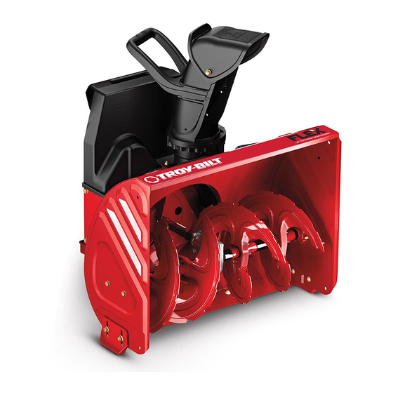
FLEX™ Snow Thrower Attachment — 23AABA6X711
WARNING
READ AND FOLLOW ALL SAFETY RULES AND INSTRUCTIONS IN THIS MANUAL
BEFORE ATTEMPTING TO OPERATE THIS MACHINE.
FAILURE TO COMPLY WITH THESE INSTRUCTIONS MAY RESULT IN PERSONAL INJURY.
TROY-BILT LLC, P.O. BOX 361131 CLEVELAND, OHIO 44136-0019
Printed In USA
Form No. 769-10250
(February 24, 2015)
Advertisement
Table of Contents

Related Manuals for Troy-Bilt FLEX 23AABA6X711


Summary of Contents for Troy-Bilt FLEX 23AABA6X711
- Page 1 READ AND FOLLOW ALL SAFETY RULES AND INSTRUCTIONS IN THIS MANUAL BEFORE ATTEMPTING TO OPERATE THIS MACHINE. FAILURE TO COMPLY WITH THESE INSTRUCTIONS MAY RESULT IN PERSONAL INJURY. TROY-BILT LLC, P.O. BOX 361131 CLEVELAND, OHIO 44136-0019 Printed In USA Form No. 769-10250...
-
Page 2: Table Of Contents
Visit us on the web at www.troybilt.com See How-to Maintenance and Parts Installation Videos at www.troybilt.com/tutorials ◊ Call a Customer Support Representative at (800) 828-5500 or (330) 558-7220 ◊ Write to Troy-Bilt LLC • P.O. Box 361131 • Cleveland, OH • 44136-0019... -
Page 3: Safe Operation Practices
Important Safe Operation Practices WARNING! This symbol points out important safety instructions which, if not followed, could endanger the personal safety and/or property of yourself and others. Read and follow all instructions in this manual before attempting to operate this machine. Failure to comply with these instructions may result in personal injury. - Page 4 Safe Handling of Gasoline Do not operate machine while under the influence of alcohol or drugs. To avoid personal injury or property damage use extreme care Muffler and engine become hot and can cause a burn. Do in handling gasoline. Gasoline is extremely flammable and the not touch.
- Page 5 Clearing a Clogged Discharge Chute According to the Consumer Products Safety Commission (CPSC) and the U.S. Environmental Protection Agency (EPA), Hand contact with the rotating impeller inside the discharge this product has an Average Useful Life of seven (7) years, chute is the most common cause of injury associated with snow or 60 hours of operation.
- Page 6 Safety Symbols This page depicts and describes safety symbols that may appear on this product. Read, understand, and follow all instructions on the machine before attempting to assemble and operate. Symbol Description READ THE OPERATOR’S MANUAL(S) Read, understand, and follow all instructions in the manual(s) before attempting to assemble and operate WARNING—...
-
Page 7: Assembly & Set-Up
Assembly & Set-Up Assembly Installing the Discharge Chute A discharge chute, wire spring, and chute band, have been included with this attachment. Please assemble them now by installing the discharge chute onto the snow thrower by following these steps: Install the wire spring into the discharge opening of the snow thrower by inserting both ends into the slots provided. - Page 8 Place some of the white lithium grease provided on the chute band as shown in Figure 3-4. Figure 3-6 Secure the chute band to itself by first aligning the two snap-fit features and pushing the two ends (1 & 2) together Figure 3-4 as shown.
- Page 9 Note: If the installation has been completed properly, a To adjust the skid shoes: click! click! click! sound will be heard when rotating the Loosen the four hex nuts (two on each side) and carriage chute to the left and right. See Figure 3-8. bolts.
- Page 10 Discharge Chute Shear Pins The position of the upper discharge chute can be adjusted to A pair of replacement auger shear pins and bow tie cotter pins control the distance that the discharged snow will be thrown, are included with this snow thrower attachment. See Figure 3-11. and the direction at which it will be discharged.
-
Page 11: Controls
Controls and Features Attachment Control Lever Attachment Control Lever Lock Chute Handle Upper Chute Drive Control Lever Chute Knob Chute Assembly Chute Clean-out Tool Skid Shoe Shave Plate Auger Figura 4-1 Engine Chute Knob Refer to the FLEX™ Base Unit Operator’s Manual for details The distance snow is thrown can be adjusted by either raising regarding all engine-related controls and features. -
Page 12: Operation
Operation Starting The Engine Once the top mount is engaged (1), and with both hands on the handle grips, tip the unit backwards somewhat Refer to the FLEX™ Power Base’s operator’s manual for engine swiftly to engage the bottom mounts (2). See Figure 5-3. starting and operating instructions. - Page 13 To Engage Drive Shut off engine as instructed in the engine manual. Remove the clean-out tool from the clip which secures it to To engage the drive, squeeze the Drive Control Lever the rear of the auger housing. completely up against the upper handle to engage the Use the shovel-shaped end of the clean-out tool to wheels.
-
Page 14: Maintenence & Adjustments
Maintenance & Adjustments Maintenance Adjusting the Auger Drive Cable After periods of extended use, and during the break-in period, it General Recommendations may be necessary to adjust the auger drive cable. Follow these • Always observe safety rules when performing any type of simple steps to adjust the auger drive cable: maintenance. - Page 15 Off-Season Storage Shave Plate and Skid Shoes The shave plate and skid shoes on the bottom of the snow If the snow thrower attachment will not be used for 30 days thrower are subject to wear. These should be checked or longer, or if it is the end of the snow season when the last periodically and replaced when necessary.
-
Page 16: Service
Service Augers Replacing the Auger Belt The augers are secured to the spiral shaft with four shear pins and Uncouple the FLEX™ Snow Thrower attachment from the cotter pins. If you hit a foreign object or ice jam, the snow thrower FLEX™... - Page 17 Note: When reinstalling the new belt, be sure that it routes Carefully tip the FLEX™ Snow Thrower Attachment forward onto the front of the auger housing as shown. Use the INSIDE of the idler pulley as shown in 1 of Figure 7-6. mounting handle called out in Figure 7-4 to tip this unit forward.
-
Page 18: Troubleshooting
Troubleshooting Problem Cause Remedy Excessive vibration or noise 1. One or more of the clutch bumpers is missing 1. Replace the three clutch bumpers with when the Attachment or worn. replacement kit part no. 753-08457. Control Lever is applied. 2. Loose parts or damaged auger. 2. -
Page 19: Replacement Parts
Replacement Parts Component Part Number and Description 954-05071 Auger Drive Belt 738-04124A Shear Pin, 1.50 714-04040 Bow-tie Cotter Pin 784-5580 Skid Shoe, Standard (steel) 931-2643 Chute Clean-out Tool 790-00121 Shave Plate 753-08457 Clutch Bumper Kit (6) Phone (800) 828-5500 to order replacement parts or a complete Parts Manual (have your full model number and serial number ready). Parts Manual downloads are also available free of charge at www.troybilt.com. - Page 20 Notes...
-
Page 21: Warranty
LIMITED WARRANTY FOR FLEX ATTACHMENT PRODUCT The limited warranty set forth herein is given by Troy-Bilt LLC to the Initial Any expendable, consumable, or routine maintenance item which Purchaser (as defined herein) with respect to a new Troy-Bilt-branded FLEX needs replacement or service as part of normal maintenance, unless... -
Page 22: Spanish
Vea videos instructivos sobre el mantenimiento y la instalación de piezas en www.troybilt.com/tutorials ◊ Llame a un representante de Asistencia al Cliente al (800) 828-5500 ó (330) 558-7220 ◊ Escriba a Troy-Bilt LLC • P.O. Box 361131 • Cleveland, OH • 44136-0019... - Page 23 Importantes medidas de seguridad ¡ADVERTENCIA! La presencia de este símbolo indica que se trata de instrucciones de seguridad importantes que se deben respetar para evitar poner en peligro su seguridad personal y/o material y la de otras personas. Lea y cumpla todas las instrucciones de este manual antes de intentar operar esta máquina.
- Page 24 Manejo seguro de la gasolina No utilice la máquina bajo la influencia de alcohol o drogas. El silenciador y el motor se calientan y pueden causar Para evitar lesiones personales o daños materiales tenga mucho quemaduras. No los toque. Mantenga a los niños alejados. cuidado al manipular la gasolina.
- Page 25 Despeje de un canal de descarga obstruido Según la Comisión de Seguridad de Productos para el Consumidor de los Estados Unidos (CPSC) y la Agencia de Protección Ambiental de los Estados Unidos (EPA), este El contacto de las manos con el impulsor rotatorio que está dentro producto tiene una vida útil media de siete (7) años ó...
- Page 26 Símbolos de seguridad En esta página se presentan y describen los símbolos de seguridad que en este producto puede tener. Lea, entienda y siga todas las instrucciones incluidas en la máquina antes de intentar armarla y hacerla funcionar. Símbolo Descripción LEA LOS MANUALES DEL OPERADOR Lea, entienda y siga todas las instrucciones incluidas en los manuales antes de intentar armarla y hacerla funcionar.
- Page 27 Montaje y Configuración Montaje Instalación del canal de descarga Con el presente accesorio se incluyó un canal de descarga, un resorte de alambre y una banda para canal. Ensámblelos ahora, para lo que debe instalar el canal de descarga en el accesorio quitanieve siguiendo estos pasos: Instale el resorte de alambre en la abertura de descarga del accesorio quitanieve para lo cual debe insertar ambos...
- Page 28 Place poco de la grasa de litio blanca en la banda Ofrecido caída, como se muestra en la Figura 3-4. Figura 3-6 Sujete la banda para el canal al canal alineando primero las dos uniones de ajuste a presión y oprimiendo los dos Figura 3-4 extremos (1 y 2) para unirlos como se indica.
- Page 29 PRECAUCIÓN: Nota: Si la instalación se realizó correctamente, se oirá un Si se utiliza una máquina quitanieves sonido como ¡clic! ¡clic! ¡clic! al girar el canal hacia la izquierda que está equipada con zapatas antideslizantes de acero y la derecha. Consulte la Figura 3-8. se pueden provocar daños a las superficies que tengan pavimento natural (por ejemplo arenisca, piedra azul, piedra caliza).
- Page 30 Canal de descarga Pasadores de cuchilla La posición del canal de descarga superior se puede ajustar de El accesorio quitanieve trae un par de pasadores de cuchilla de la manera de controlar la distancia a la que se arrojará la nieve barrena y pasadores de chaveta con unión curva de reemplazo.
- Page 31 Controles y Características Palanca de control del accesorio Bloqueo de la palanca de control del accesorio Manija del canal Canal superior Palanca de control de la transmisión Perilla del canal Conjunto del canal Herramienta de limpieza del canal Zapata antideslizante Placa de raspado Barrena Figura 4-1...
- Page 32 Funcionamiento Encendido del motor Una vez que se engancha el montaje superior (1), y con ambas manos en las empuñaduras de las manijas, incline suavemente la unidad hacia atrás para enganchar los montajes inferiores Consulte el manual del operador de la base de potencia FLEX™ para obtener las instrucciones para el arranque y el funcionamiento (2).
- Page 33 Procedimiento para engranar la transmisión Suelte tanto la palanca de control del accesorio como la palanca de control de la transmisión. Para activar la transmisión, apriete la palanca de control Apague el motor como se indica en el manual del motor. de la transmisión completamente contra la manija de control Saque la herramienta de limpieza del pasador que la ajusta superior para engranar las ruedas.
- Page 34 Mantenimiento y Ajustes Mantenimiento Ajuste del cable de transmisión de la barrena Después de períodos de uso prolongado y durante el período de Recomendaciones generales descanso, puede ser necesario ajustar el cable de transmisión de la barrena. Siga estos simples pasos para ajustar dicho cable: •...
- Page 35 Almacenamiento fuera de temporada Placa de raspado y zapatas antideslizantes La placa de raspado y las zapatas antideslizantes ubicadas en la base Si no se va a utilizar el accesorio quitanieve durante 30 días o más, o si de la máquina quitanieve están sujetas a desgaste. Debe controlarlas es el final de la temporada de nieve y ya no existe posibilidad de que periódicamente y reemplazarlas cuando sea necesario.
- Page 36 Servicio Barrenas Cambio de la correa de la barrena Las barrenas están ajustadas al eje espiral con cuatro pasadores de Desacople el accesorio quitanieve FLEX™ de la unidad base cuchilla y pasadores de chaveta. La máquina quitanieve está diseñada FLEX™ usando el soporte e inclinando la unidad base hacia de manera que los pasadores se quiebran si golpea un objeto extraño adelante.
- Page 37 Nota: Incline con cuidado el accesorio quitanieve FLEX™ hacia Al reinstalar la nueva correa, asegúrese de que pase adelante sobre el frente de la caja de la barrena como se indica. por el INTERIOR de la polea loca, como se indica en 1 de la Use la manija de montaje que se indicó...
- Page 38 Solución De Problemas Problema Causa Remedio La vibración excesiva o 1. Uno o más de los topes de embrague falta o 1. Vuelva a colocar los tres topes de embrague ruido cuando se aplica el desgastado. con el reemplazo kit ref. 753 a 08.457. Anexo palanca de control.
- Page 39 Piezas de reemplazo Componente Número de pieza y Descripción 954-05071 Auger correa de transmisión 738-04124A Shear Pin, 1.50 714-04040 Pajarita Chaveta 784-5580 Zapato Skid, Standard (acero) 931-2643 Herramienta de limpieza del canal de salida 790-00121 Placa Shave 753-08457 Pegatina Kit de embrague (6) Teléfono (800) 828-5500 para solicitar piezas de reemplazo o un Manual de Repuestos completo (tenga el número de modelo y número de serie).
- Page 40 Período de la Garantía. NO EXISTEN GARANTÍAS IMPLÍCITAS, ENTRE LAS QUE SE INCLUYEN, Durante el Período de la Garantía, Troy-Bilt LLC reparará o reemplazará, a su juicio, A TÍTULO DE EJEMPLO, LAS GARANTÍAS IMPLÍCITAS DE COMERCIABILIDAD cualquier pieza original que esté...