Table of Contents
Advertisement
Available languages
Available languages
Safe Operation Practices • Set-Up • Operation • Maintenance • Service • Troubleshooting • Warranty
O
'
M
peratOr
s
anual
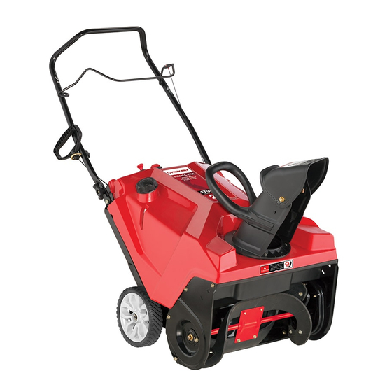
— Squall 2100 Shown —
Single-Stage Snow Thrower
Squall 210 & Squall 2100
WARNING
READ AND FOLLOW ALL SAFETY RULES AND INSTRUCTIONS IN THIS MANUAL
BEFORE ATTEMPTING TO OPERATE THIS MACHINE.
FAILURE TO COMPLY WITH THESE INSTRUCTIONS MAY RESULT IN PERSONAL INJURY.
TROY-BILT LLC, P.O. BOX 361131 CLEVELAND, OHIO 44136-0019
Printed In USA
Form No. 769-07131
(May 4, 2011)
Advertisement
Chapters
Table of Contents

Related Manuals for Troy-Bilt Squall2100


Summary of Contents for Troy-Bilt Squall2100
- Page 1 READ AND FOLLOW ALL SAFETY RULES AND INSTRUCTIONS IN THIS MANUAL BEFORE ATTEMPTING TO OPERATE THIS MACHINE. FAILURE TO COMPLY WITH THESE INSTRUCTIONS MAY RESULT IN PERSONAL INJURY. TROY-BILT LLC, P.O. BOX 361131 CLEVELAND, OHIO 44136-0019 Printed In USA Form No. 769-07131...
-
Page 2: Table Of Contents
Choose from the options below: ◊ Visit us on the web at www.troybilt.com ◊ Call a Customer Support Representative at (800) 828-5500 or (330) 558-7220 ◊ Write us at Troy-Bilt LLC • P.O. Box 361131 • Cleveland, OH • 44136-0019... -
Page 3: Safe Operation Practices
Important Safe Operation Practices WARNING! This symbol points out important safety instructions which, if not followed, could endanger the personal safety and/or property of yourself and others. Read and follow all instructions in this manual before attempting to operate this machine. Failure to comply with these instructions may result in personal injury. - Page 4 Safe Handling of Gasoline Never run an engine indoors or in a poorly ventilated area. Engine exhaust contains carbon monoxide, an odorless To avoid personal injury or property damage use extreme care and deadly gas. in handling gasoline. Gasoline is extremely flammable and the Do not operate machine while under the influence of vapors are explosive.
- Page 5 Clearing a Clogged Discharge Chute According to the Consumer Products Safety Commission (CPSC) and the U.S. Environmental Protection Agency (EPA), Hand contact with the rotating impeller inside the discharge this product has an Average Useful Life of seven (7) years, chute is the most common cause of injury associated with snow or 60 hours of operation.
-
Page 6: Safety Symbols
Safety Symbols This page depicts and describes safety symbols that may appear on this product. Read, understand, and follow all instructions on the machine before attempting to assemble and operate. Symbol Description READ THE OPERATOR’S MANUAL(S) Read, understand, and follow all instructions in the manual(s) before attempting to assemble and operate WARNING—... -
Page 7: Assembly & Set-Up
Assembly & Set-Up Contents of Carton • One Snow Thrower • One 20 oz. Bottle 5W-30 Oil • Two Ignition Keys • One Chute Assembly • One Chute Rotation Control (If equip.) • One Set of Drift Cutters (If equip.) •... - Page 8 Align the holes in the chute base with the holes in the Installing the Drift Cutters (If so equipped) lower chute and secure with the previously removed hex Remove the carriage bolts and flange lock nuts from the washer screws. See Fig. 3-4. drift cutters.
- Page 9 Slowly pull the recoil starter handle up towards the eye bolt. Slip the recoil starter rope into the eye bolt from the back of the snow thrower. See Fig. 3-7. Securely tighten the eye bolt and handle knob. Set-Up Adding Oil Refer to the Engine Operator’s Manual packed with your snow thrower for information on adding and checking oil.
-
Page 10: Controls & Features
Controls & Features Auger Control Recoil Starter Handle Chute Rotation Control EZ Chute Low-Crank Chute Assembly Drift Cutters Auger Shave Plate Figure 4-1 Chute Assembly NOTE: This Operator’s Manual covers several models. Snow thrower features may vary by model. Not all features in this manual are applicable to all snow thrower models and the snow EZ Chute (If so equipped) thrower depicted may differ from yours. - Page 11 Recoil Starter Handle The recoil starter handle is used to manually start the engine. Chute Rotation Control (If so equipped) The chute rotation control is located on the back of the snow thrower. To rotate the chute to the left, squeeze the lever against the chute rotation control and rotate left.
-
Page 12: Operation
Operation Starting & Stopping the Engine Low-Crank Chute Assembly (If so equipped) Rotate the discharge chute to the left or right using the WARNING! Always keep hands and feet clear of chute rotation control. See Fig. 5-2. moving parts. Do not use a pressurized starting fluid. -
Page 13: Maintenance & Adjustment
Maintenance & Adjustments Adjustments Auger Control Cable As a result of both the auger control cable and the auger drive belt WARNING! Before servicing, repairing or stretching due to wear, periodic adjustments may be necessary. If inspecting the snow thrower, disengage the auger the auger seems to hesitate when rotating, proceed as follows: control. - Page 14 NOTE: The bottom of the panel has tabs that help hold it in place. NOTE: An oil drain extension kit is available separately. Contact your local Troy-Bilt dealer or contact Troy-Bilt’s Customer Support for kit #753-06684. Change the oil and/or the spark plug as instructed in your Engine Operator’s manual.
-
Page 15: Service
Service Replacing Belt To replace the belt follow these instructions and refer to Fig. 7-3: Run the snow thrower until the fuel tank is empty. Drive Pulley Pull the recoil starter handle until resistance is felt. Then tip the snow thrower back until it rests on the handles. Idler Pulley Slide a board up through the auger and through the chute to secure the auger in place. - Page 16 Replacing Auger Paddles Replacing Shave Plate The snow thrower auger’s rubber paddles are subject to wear The shave plate is attached to the bottom of the auger and should be replaced if any signs of excessive wear are present. housing and is subject to wear. It should be checked periodically.
-
Page 17: Troubleshooting
Troubleshooting Problem Cause Remedy Excessive vibration 1. Loose parts or damaged auger. 1. Stop engine immediately and disconnect spark plug wire. Check for possible damage. Tighten all bolts and nuts. Repair as needed. If the problem persists, take snow thrower to an authorized service dealer. -
Page 18: Replacement Parts
Replacement Parts Component Part Number and Description 731-08171 Shave Plate 954-04050 Belt V-Type 753-06469 Rubber Auger Paddle Kit (Includes 2 paddles and 12 hex washer screws) 731-05632 946-04782 Clutch Cable (Squall 210) 946-04701 Clutch Cable (Squall 2100) 634-04607 Wheel Assembly, 7 x 2 (Squall 210) 734-04033 Wheel Assembly, 8 x 2.125 (Squall 2100) Phone (800) 800-7310 to order replacement parts or a complete Parts Manual (have your full model number and serial number ready). - Page 19 Notes...
-
Page 20: Warranties
MANUFACTURER’S LIMITED WARRANTY FOR The limited warranty set forth below is given by Troy-Bilt LLC with c. Service completed by someone other than an authorized service respect to new merchandise purchased and used in the United States dealer. and/or its territories and possessions, and by MTD Products Limited d. - Page 21 LEA Y RESPETE TODAS LAS NORMAS DE SEGURIDAD E INSTRUCCIONES INCLUIDAS EN ESTE MANUAL ANTES DE PONER EN FUNCIONAMIENTO ESTA MÁQUINA. SI NO RESPETA ESTAS INSTRUCCIONES PUEDE PROVOCAR LESIONES PERSONALES. TROY-BILT LLC, APARTADO POSTAL 361131 CLEVELAND, OHIO 44136-0019 Impreso en Estados Unidos de América Formulario No. 769-07131...
- Page 22 Elija entre las opciones que se presentan a continuación: ◊ Visite nuestro sitio web en www.troybilt.com ◊ Llame a un representante de Asistencia al Cliente al (800) 828-5500 ó (330) 558-7220 ◊ Escríbanos a Troy-Bilt LLC • P.O. Box 361131 • Cleveland, OH • 44136-0019...
-
Page 23: Medidas Importantes De Seguridad
Medidas importantes de seguridad ADVERTENCIA! ¡ La presencia de este símbolo indica que se trata de instrucciones importantes de seguridad que se deben respetar para evitar poner en peligro su seguridad personal y/o material y la de otras personas. Lea y siga todas las instrucciones de este manual antes de poner en funcionamiento esta máquina. - Page 24 Manejo seguro de la gasolina Nunca opere la máquina si falta un montaje del canal o si el mismo está dañado. Mantenga todos los dispositivos de Para evitar lesiones personales o daños materiales tenga mucho seguridad en su lugar y en funcionamiento. cuidado cuando trabaje con gasolina.
- Page 25 Si se presentan situaciones que no están previstas en este Nunca almacene la máquina o el recipiente de combustible manual, sea cuidadoso y use el sentido común. Póngase en en un espacio cerrado donde haya fuego, chispas o luz contacto con Asistencia al Cliente para solicitar ayuda y el piloto como por ejemplo, calentadores de agua, hornos, nombre del distribuidor de servicio más cercano.
- Page 26 Símbolos de Seguridad Esta página describe los símbolos y figuras de seguridad internacionales que pueden aparecer en este producto. Lea el manual del operador para obtener la información terminada sobre seguridad, reunirse, operación y mantenimiento y reparación. Símbolo Descripción LEA EL MANUAL DEL OPERADOR (S) Lea, entienda, y siga todas las instrucciones en el manual (es) antes de intentar reunirse y funcionar.
-
Page 27: Montaje Y Configuración
Montaje y Configuración Contenido de la caja de cartón • Una máquina quitanieve • Una botella de 20 oz. de aceite 5W-30 • Dos llaves de encendido • Un conjunto de canal • Un control de rotación del canal • Un conjunto de cortadores de desplaza- (si viene equipado). - Page 28 Alinee los orificios de la base del canal con los orificios Instalación de los cortadores de desplazamiento de nieve (si del canal inferior y sujételo con los tornillos para arandela vienen equipados) hexagonal que extrajo anteriormente. Vea la Fig. 3-4. Extraiga los pernos del carro y las tuercas de seguridad con brida de los cortadores de desplazamiento de nieve.
- Page 29 Lentamente tire de la manija del arrancador manual hacia el perno de ojo. Deslice el cable de arranque de arranque en la argolla de la parte posterior de la máquina quitanieves. Véase la Figura 3-7. Apriete bien el tornillo de ojo y la perilla del mango. Configuración Carga de combustible Consulte el manual de operación del motor embalado con...
-
Page 30: Controles Y Características
Controles y Características Control de la barrena Manija del arrancador de retroceso Control de rotación del canal Montaje de la Canal EZ manivela del canal inferior Cortadores de desplazamiento de nieve Barrena Placa de raspado Figura 4-1 Montaje del canal NOTA: Este manual de operación cubre distintos modelos. - Page 31 Manija del arrancador de retroceso La manija del arrancador de retroceso se utiliza para encender manualmente el motor. Control de rotación del canal (si viene equipado) El control de rotación del canal está ubicado en la parte posterior de la máquina quitanieve. Para rotar el canal hacia la izquierda, apriete la palanca contra el control de rotación del canal y rote hacia la izquierda.
-
Page 32: Funcionamiento
Funcionamiento Arranque y detención del motor Conjunto de la manivela del canal inferior (de venir equipado) Haga rotar el canal de descarga hacia la izquierda o ¡ADVERTENCIA! Siempre mantenga las manos y derecha usando el control de rotación del canal. Vea la los pies alejados de las partes móviles. -
Page 33: Mantenimiento Y Ajustes
Mantenimiento y Ajustes Ajustes Inspeccione la bujía. Si está húmeda, limpie cualquier resto de aceite antes de volver a instalar. ¡ADVERTENCIA! Antes de realizar tareas de Cable de control de la barrena mantenimiento, reparación o inspección en la máquina quitanieve, desengrane el control de la Es posible que necesite realizar ajustes periódicos debido al barrena. - Page 34 NOTA: Un kit de extensión del drenaje de aceite se encuentra disponible por separado. Contacte a su distribuidor Troy-Bilt local o contacte a Asistencia al Cliente de Troy-Bilt para el kit #753-06684. Cambie el aceite y/o bujía como se instruye en su manual de operación del motor.
-
Page 35: Servicio
Servicio Reemplazo de las correas Para volver a colocar la correa siga estas instrucciones y consulte la Fig. 7-3: Ponga en marcha la máquina quitanieve hasta que el tanque de combustible esté vacío. Polea de transmisión Jale de la manija del arrancador de retroceso hasta sentir resistencia. - Page 36 Reemplazo de las paletas de la barrena Reemplazo de la placa de raspado Las paletas de caucho de la barrena de la máquina quitanieve La placa de raspado está adosada al fondo de la caja se desgastan y se las debe cambiar si se presentan signos de de la barrena y sujeta a desgaste.
-
Page 37: Solución De Problemas
Solución de Problemas Problema Causa Solución Vibración excesiva 1. Hay piezas que están flojas o la barrena está 1. Detenga el motor de inmediato y desconecte dañada. el cable de la bujía. Controle si la máquina está dañada. Ajuste todos los pernos y las tuercas. - Page 38 Notas...
- Page 39 9 — n ección otaS...
-
Page 40: Garantías
Las disposiciones de esta garantía cubren el recurso de reparación helicoidales y neumáticos. única y exclusiva que surge de la venta. Troy-Bilt no se hará responsable de ninguna pérdida o daño incidental o resultante, Accesorios — Troy-Bilt garantiza que los accesorios de este incluyendo sin limitación, los gastos incurridos para los servicios...