Table of Contents
Advertisement
Safe Operation Practices • Set-Up • Operation • Maintenance • Service • Troubleshooting • Warranty
O
'
M
peratOr
s
anual
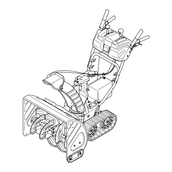
Snow Tracker 2690
WARNING
READ AND FOLLOW ALL SAFETY RULES AND INSTRUCTIONS IN THIS MANUAL
BEFORE ATTEMPTING TO OPERATE THIS MACHINE.
FAILURE TO COMPLY WITH THESE INSTRUCTIONS MAY RESULT IN PERSONAL INJURY.
TROY-BILT LLC, P.O. BOX 361131 CLEVELAND, OHIO 44136-0019
Printed In USA
Form No. 769-04054
(April 28, 2007)
Advertisement
Table of Contents

Related Manuals for Troy-Bilt 2690


Summary of Contents for Troy-Bilt 2690
- Page 1 READ AND FOLLOW ALL SAFETY RULES AND INSTRUCTIONS IN THIS MANUAL BEFORE ATTEMPTING TO OPERATE THIS MACHINE. FAILURE TO COMPLY WITH THESE INSTRUCTIONS MAY RESULT IN PERSONAL INJURY. TROY-BILT LLC, P.O. BOX 361131 CLEVELAND, OHIO 44136-0019 Printed In USA Form No. 769-04054...
-
Page 2: Table Of Contents
Call a Customer Support Representative at (800) 828-5500 or (330) 558-7220 ◊ Write us at Troy-Bilt LLC • P.O. Box 361131 • Cleveland, OH • 44136-0019 If you have any problems or questions concerning the machine, phone a authorized Troy-Bilt service dealer or contact us directly. -
Page 3: Safe Operation Practices
Important Safe Operation Practices WARNING! This symbol points out important safety instructions which, if not followed, could endanger the personal safety and/or property of yourself and others. Read and follow all instructions in this manual before attempting to operate this machine. Failure to comply with these instructions may result in personal injury. - Page 4 Safe Handling of Gasoline To avoid personal injury or property damage use extreme care in handling gasoline. Gasoline is extremely flammable and the vapors are explosive. Serious personal injury can occur when gasoline is spilled on yourself or your clothes which can ignite. Wash your skin and change clothes immediately.
- Page 5 Maintenance & Storage Never tamper with safety devices. Check their proper operation regularly. Refer to the maintenance and adjustment sections of this manual. Before cleaning, repairing, or inspecting machine disengage all control levers and stop the engine. Wait until the auger/impeller come to a complete stop. Disconnect the spark plug wire and ground against the engine to prevent unintended starting.
-
Page 6: Safety Symbols
Safety Symbols This page depicts and describes safety symbols that may appear on this product. Read, understand, and follow all instructions on the machine before attempting to assemble and operate. Symbol WARNING! Your Responsibility—Restrict the use of this power machine to persons who read, understand and follow the warnings and instructions in this manual and on the machine. -
Page 7: Assembly & Set-Up
Assembly & Set-Up Contents of Carton • Two Ignition Keys • One 110V Extension Cord Assembly Handle Place the shift lever in the Forward-6 position Remove the lower plastic wing nut and carriage bolt from each side of the upper handle; then raise the upper handle assembly until it snaps over the lower handle. - Page 8 Place chute assembly onto chute base and secure chute control assembly to chute support bracket with clevis pin and cotter pin removed earlier. See See Fig. 3-3. Figure 3-3 Finish securing chute control assembly to chute support bracket with wing nut and hex screw removed earlier. See Fig.
- Page 9 Chute Clean-Out Tool The chute clean-out tool is fastened to the top of the auger housing with a mounting clip and a cable tie at the factory. Cut the cable tie before operating the snow thrower. See Fig. 3-7. Chute Clean-Out Tool Figure 3-7 Fuel Recommendations Use automotive gasoline (unleaded or low leaded to minimize...
- Page 10 Checking Oil Level CAUTION: The engine is shipped with oil in the engine. You must, however, check the oil level prior to operating the snow thrower. Running the engine with insufficient oil can cause serious engine damage and void the engine warranty. NOTE: Be sure to check the engine on a level surface with the engine stopped.
- Page 11 Auger Control WARNING! Prior to operating your snow thrower, carefully read and follow all the instructions below. Perform all adjustments to verify your snow thrower is operating safely and properly. Check the adjustment of the auger control as follows: When the auger control is released and in the disengaged “up”...
-
Page 12: Controls
Controls and Features Track Lock Lever Packed Snow Normal Snow Chute Assembly Chute Cleanout Tool Auger WARNING! Read, understand, and follow all instructions and warnings on the machine and in this manual before operating. Shift Lever The shift lever is located in the right side of the handle panel and is used to determine both the ground speed and direction of travel. -
Page 13: Auger Control
Track Drive Control / Auger Clutch Lock* The track drive control is located on the right handle. Squeeze the control grip against the handle to engage the track drive. Release to stop. Note: Always release the drive control before changing speeds. Failure to do so will result in increased wear on your machine’s drive system. -
Page 14: Ignition Key
Oil Fill Engine oil level can be checked and oil added through the oil fill. Oil Drain Engine oil can be drained through the oil drain. Muffler Engine exhaust exists the engine via the muffler. WARNING! Do not touch the muffler while the engine is hot or running. -
Page 15: Operation
Operation Starting the Engine WARNING! Always keep hands and feet clear of moving parts. Do not use a pressurized starting fluid. Vapors are flammable. NOTE: Allow the engine to warm up for a few minutes after starting. The engine will not develop full power until it reaches operating temperatures. -
Page 16: Stopping The Engine
Recoil Starter CAUTION! Do not pull the starter handle while the engine running. WARNING! To avoid unsupervised engine operation, never leave the engine unattended while running. Turn the engine off after use and remove ignition key Insert the ignition key fully into the slot, Fig. 5-1. Make sure it snaps into place. -
Page 17: Maintenance & Adjustment
Maintenance & Adjustments Maintenance Engine Refer to the Engine Maintenance section. Shave Plate and Skid Shoes The shave plate and skid shoes on the bottom of the snow thrower are subject to wear. They should be checked periodically and replaced when necessary. To remove the skid shoes: Remove the four carriage bolts and hex flange nuts which secure them to the snow thrower. -
Page 18: Adjustments
NOTE: When lubricating the hex shaft, be careful not to get any oil on the aluminum drive plate or the rubber friction wheel. Doing so will hinder the snow thrower’s drive system. Wipe off any excess or spilled oil. Auger Shaft At least once a season, remove the shear pins from the auger shaft. - Page 19 Drive Control When the drive control is released and in the disengaged “up” position, the cable should have very little slack. It should NOT be tight. NOTE: If excessive slack is present in the drive cable or if the snow thrower’s drive is disengaging intermittently during operation, the cable may be in need of adjustment.
-
Page 20: Engine Maintenance
Engine Maintenance WARNING! To prevent accidental start-up, shut off the engine and remove the ignition key before performing any type of engine maintenance. Maintenance Schedule Tasks First 5 Hrs. Each Use or Every 5 Hrs. Check engine oil Change engine oil Check spark plug Service spark plug Clean exhaust area... -
Page 21: Spark Plug
Reinstall the oil filler cap/dipstick securely. CAUTION! Thoroughly wash your hands with soap and water as soon as possible after handling used oil. NOTE: Please dispose of used motor oil in a manner that is friendly to the environment. Take it to a recyling center or other collection center. - Page 22 Off-Season Storage Engines stored over 30 days need to be drained of fuel to prevent deterioration and gum from forming in the fuel system or on essential carburetor parts. If the gasoline in your engine deteriorates during storage, you may need to have the carburetor, and other fuel system components, serviced or replaced.
-
Page 23: Service
Service Belt Replacement Auger Belt NOTE: It is not necessary to remove both belts in order to change either one. If changing just one belt, be certain to check the condition of the other belt. Remove the plastic belt cover at the front of the engine by removing the two self-tapping screws. - Page 24 Unhook the idler spring from the hex bolt on the auger housing. See Fig. 7-4. Stop Bolt Hex Bolt Figure 7-4 Lift the auger belt from the auger pulley, and slip belt between the support bracket and the auger pulley. Repeat this step for the front auger belt.
-
Page 25: Friction Wheel Removal
Slip the drive belt off the pulley and between friction wheel and drive pulley. See Fig. 7-7. Drive Pulley Drive Belt Figure 7-7 Remove and replace belt in the reverse order. NOTE: Engaging the drive control will ease re-assembly of the belt. - Page 26 If repacing the entire assembly, put the new friction wheel assembly in place and follow the steps in reverse to re- assemble. If you only want to replace the friction wheel rubber continue with step 7. Remove the four screws from the friction wheel assembly. See Fig.
-
Page 27: Troubleshooting
Troubleshooting Problem Engine fails to start Fuel tank empty, or stale fuel. Blocked fuel line. Choke not in the ON position. Faulty spark plug. Safety key not in ignition switch on engine. Spark plug wire disconnected. Primer button not being used properly. Engine runs erratic Engine running on CHOKE. -
Page 28: Replacement Parts
Replacement Parts Component Phone (800) 800-7310 to order replacement parts or a complete Parts Manual (have your full model number and serial number ready). Parts Manual downloads are also available free of charge at www.mtdproducts.com. Part Number and Description 929-0071 Extension Cord, 110V 954-04050 Auger Drive Belt... - Page 29 Notes...
- Page 30 Troy-Bilt LLC (Troy-Bilt) and The United States Environment Protection Agency (U. S. EPA) The U. S. EPA and Troy-Bilt are pleased to explain the emissions control system warranty on your model year 2005 and later small off-road engine. New small off-road engines must be designed, built and equipped to meet the stringent anti-smog standards. Troy-Bilt must warranty the emission control system on your engine for the period of time listed below, provided there has been no abuse, neglect or improper maintenance of your small off-road engine.
- Page 31 (c) Troy-Bilt will include a copy of the following emission warranty parts list with each new engine, using those portions of the list applicable to the engine.
- Page 32 MANUFACTURER’S LIMITED WARRANTY FOR The limited warranty set forth below is given by Troy-Bilt LLC with respect to new merchandise purchased and used in the United States and/or its territories and possessions, and by MTD Products Limited with respect to new merchandise purchased and used in Canada and/or its territories and possessions (either entity respectively, “Troy-Bilt”).