Table of Contents
Advertisement
Available languages
Available languages
Safe Operation Practices • Set-Up • Operation • Maintenance • Service • Troubleshooting • Warranty
O
'
M
peratOr
s
anual
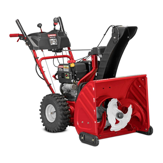
Three Stage Snow Thrower — Vortex 2490 & Vortex 2890
WARNING
READ AND FOLLOW ALL SAFETY RULES AND INSTRUCTIONS IN THIS MANUAL
BEFORE ATTEMPTING TO OPERATE THIS MACHINE.
FAILURE TO COMPLY WITH THESE INSTRUCTIONS MAY RESULT IN PERSONAL INJURY.
TROY-BILT LLC, P.O. BOX 361131 CLEVELAND, OHIO 44136-0019
Printed In USA
Form No. 769-09814
(May 29, 2014)
Advertisement
Table of Contents

Related Manuals for Troy-Bilt Vortex2490


Summary of Contents for Troy-Bilt Vortex2490
- Page 1 READ AND FOLLOW ALL SAFETY RULES AND INSTRUCTIONS IN THIS MANUAL BEFORE ATTEMPTING TO OPERATE THIS MACHINE. FAILURE TO COMPLY WITH THESE INSTRUCTIONS MAY RESULT IN PERSONAL INJURY. TROY-BILT LLC, P.O. BOX 361131 CLEVELAND, OHIO 44136-0019 Printed In USA Form No. 769-09814...
-
Page 2: Table Of Contents
Visit us on the web at www.troybilt.com See How-to Maintenance and Parts Installation Videos at www.troybilt.com/tutorials ◊ Call a Customer Support Representative at (800) 828-5500 or (330) 558-7220 ◊ Write to Troy-Bilt LLC • P.O. Box 361131 • Cleveland, OH • 44136-0019... -
Page 3: Safe Operation Practices
Important Safe Operation Practices WARNING! This symbol points out important safety instructions which, if not followed, could endanger the personal safety and/or property of yourself and others. Read and follow all instructions in this manual before attempting to operate this machine. Failure to comply with these instructions may result in personal injury. - Page 4 Safe Handling of Gasoline Never run an engine indoors or in a poorly ventilated area. Engine exhaust contains carbon monoxide, an odorless To avoid personal injury or property damage use extreme care and deadly gas. in handling gasoline. Gasoline is extremely flammable and the Do not operate machine while under the influence of vapors are explosive.
- Page 5 Clearing a Clogged Discharge Chute According to the Consumer Products Safety Commission (CPSC) and the U.S. Environmental Protection Agency (EPA), Hand contact with the rotating impeller inside the discharge this product has an Average Useful Life of seven (7) years, chute is the most common cause of injury associated with snow or 60 hours of operation.
- Page 6 Safety Symbols This page depicts and describes safety symbols that may appear on this product. Read, understand, and follow all instructions on the machine before attempting to assemble and operate. Symbol Description READ THE OPERATOR’S MANUAL(S) Read, understand, and follow all instructions in the manual(s) before attempting to assemble and operate WARNING—...
-
Page 7: Assembly & Set-Up
Assembly & Set-Up Contents of Carton • One Snow Thrower • Two Replacement Auger Shear Pins • One Chute Assembly • One Chute Control Rod • One Product Registration Card • One Engine Operator’s Manual • One Snow Thrower Operator’s Manual Assembly Remove all loose parts before assembling. - Page 8 Insert chute control rod into chute control head. Push rod Squeeze the trigger on the joystick and rotate the chute by as far into chute control head as possible, keeping the holes hand to face forward. The holes in the chute control input in the rod pointing upward.
- Page 9 Insert the chute control rod into the pinion gear below the joystick. Make sure to line up the hole in the rod with the arrow on the pinion gear. See Figure 3-8. NOTE: The chute control rod will fit snuggly into the pinion gear.
- Page 10 Set-Up Tire Pressure WARNING: Under any circumstance do not exceed Shear Pins manufacturer’s recommended psi. Equal tire A pair of replacement auger shear pins and bow tie cotter pins pressure should be maintained at all times. Excessive are included with your snow thrower. Store them in your snow pressure when seating beads may cause tire/rim thrower’s dash panel until needed.
-
Page 11: Auger Control
To adjust the skid shoes: With the throttle control in the FAST (rabbit) position and the auger control in the disengaged “up” position, walk to Loosen the four hex nuts (two on each side) and carriage the front of the machine. bolts. -
Page 12: Controls
Controls and Features Drive Control Shift Lever 4-Way Chute Directional Control Auger Control Headlight Heated Grips Steering Trigger Control Chute Assembly Clean Out Tool Augers Skid Shoe Figure 4-1 Skid Shoes Snow thrower controls and features are described below and illustrated in Figure 4-1. - Page 13 Auger Control Heated Grips CAUTION: It is recommended that you wear gloves when using the heated grip. If the heated grip become too hot, turn it off. To activate the heated grips, move the switch found on the rear of the dash panel into the ON position. To turn off the heated grips, move the switch found on the rear of the dash panel to the The auger control is located on the left handle.
- Page 14 4-Way Chute Directional Control The chute directional control is located on the left side of the dash panel. • To change the direction in which snow is thrown, squeeze the button on the joy-stick and pivot the joy-stick to the right or to the left.
-
Page 15: Operation
Operation Starting and Stopping the Engine Replacing Shear Pins Refer to the Engine Operator’s Manual packed with your snow The augers are secured to the spiral shaft with shear pins and thrower for instructions on starting and stopping the engine. cotter pins. -
Page 16: Maintenance & Adjustment
Maintenance & Adjustments Maintenance Engine Refer to the Engine Operator’s Manual. Tire Pressure Refer to Assembly and Set-up section for information regarding tire pressure. Shave Plate and Skid Shoes The shave plate and skid shoes on the bottom of the snow thrower are subject to wear. - Page 17 Adjustments Gear Shaft The gear (hex) shaft should be lubricated at least once a season Shift Cable or after every twenty-five (25) hours of operation. If the full range of speeds (forward and reverse) cannot be Allow the engine to run until it is out of fuel. achieved, adjust the shift cable as follows: Carefully pivot the snow thrower up and forward so that it Place the shift lever in the fastest forward speed position.
- Page 18 Drive Control Chute Control Rod When the drive control is released and in the disengaged “up” To adjust the chute control rod, proceed as follows: position, the cable should have very little slack. It should NOT be Remove the hairpin clip from the hole closest to the chute tight.
-
Page 19: Service
Service Belt Replacement Loosen and remove the two bolts and flat washers securing the belt guide. See Figure 7-2. Remove belt guide. Auger Belt To remove and replace your snow thrower’s auger belt, proceed as follows: Allow the engine to run until it is out of fuel. Do not attempt to pour fuel from the engine. - Page 20 NOTE: Engaging the auger control will ease removal and Carefully pivot the snow thrower up and forward so that it rests on the auger housing. reinstallation of the belt. Remove the frame cover from the underside of the snow thrower by removing the self-tapping screws which secure it.
-
Page 21: Troubleshooting
Troubleshooting Problem Cause Remedy Engine fails to start 1. Choke not in CHOKE position. 1. Move choke to CHOKE position. 2. Spark plug wire disconnected. 2. Connect wire to spark plug. 3. Fuel tank empty or stale fuel. 3. Fill tank with clean, fresh gasoline. 4. -
Page 22: Replacement Parts
Replacement Parts Component Part Number and Description 954-04195A Auger Drive Belt 954-04201A Wheel Drive Belt 684-04153C Friction Wheel Assembly 935-04054 Friction Wheel Rubber 925-1629 Lamp, 12V 738-04124A Shear Pin, 1.50 714-04040 Bow-tie Cotter Pin 790-00091 Slide Shoe, Deluxe 931-2643 Chute Clean-out Tool 790-00120 Shave Plate (Vortex 2490) 790-00118... -
Page 23: Attachments
Attachments & Accessories The following attachments and accessories are available for your Troy-Bilt snow thrower. Phone (800) 828-5500 for information regarding compatibility, price and availability (have your full model number and serial number ready). Model Number Description 929-0071A Extension Cord, 110V... - Page 24 In the U.S.A. inability to use the product. Check your Yellow Pages, or contact Troy-Bilt LLC at P .O. Box 361131, This limited warranty shall not extend to anyone other than the Cleveland, Ohio 44136-0019, or call 1-866-840-6483, original purchaser or to the person for whom it was purchased as a 1-330-558-7220 or log on to our Web site at www.troybilt.com.
- Page 25 LEA Y SIGA TODAS LAS INSTRUCCIONES DE ESTE MANUAL ANTES DE PONER EN FUNCIONAMIENTO ESTA MÁQUINA. SI NO RESPETA ESTAS INSTRUCCIONES PUEDE PROVOCAR LESIONES PERSONALES. TROY-BILT LLC, P.O. BOX 361131 CLEVELAND, OHIO 44136-0019 Impreso en Estados Unidos de América Formulario No. 769-09814...
- Page 26 Ver Vídeos demostrativos de instalación de mantenimiento y piezas en www.troybilt.com/Tutorials ◊ Llame a un representante de Asistencia al Cliente al (800) 828-5500 ó (330) 558-7220 ◊ Escríbanos a Troy-Bilt LLC • P.O. Box 361131 • Cleveland, OH • 44136-0019...
- Page 27 Medidas Importantes de Seguridad ADVERTENCIA! ¡ La presencia de este símbolo indica que se trata de instrucciones importantes de seguridad que se deben respetar para evitar poner en peligro su seguridad personal y/o material y la de otras personas. Lea y siga todas las instrucciones de este manual antes de poner en funcionamiento esta máquina.
- Page 28 Nunca intente realizar ajustes mientras el motor está La palanca de control de la barrena / impulsor es un dispositivo de seguridad. Nunca evite su funcionamiento. en marcha excepto en los casos específicamente De hacerlo la operación de la máquina es riesgosa y puede recomendados en el manual del operador.
- Page 29 Para encender el motor, jale de la cuerda lentamente hasta Verifique frecuentemente la línea de combustible, el que sienta resistencia, luego jale rápidamente. El repliegue tanque, el tapón, y los accesorios buscando rajaduras o rápido de la cuerda de arranque (tensión de retroceso) le pérdidas.
- Page 30 Símbolos de Seguridad Esta página describe los símbolos y figuras de seguridad internacionales que pueden aparecer en este producto. Lea el manual del operador para obtener la información terminada sobre seguridad, reunirse, operación y mantenimiento y reparación. Símbolo Descripción LEA EL MANUAL DEL OPERADOR (S) Lea, entienda, y siga todas las instrucciones en el manual (es) antes de intentar reunirse y funcionar.
- Page 31 Montaje y Configuración Contenido de la caja • Una máquina quitanieve • Dos pasadores de cuchilla de • Una tarjeta para registrar el barrena de repuesto producto • Un Manual del Operador de la • Varilla hexagonal • Canal de montaje Máquina Quitanieve •...
- Page 32 Montaje del canal Lugar en la tolva tolva de base y garantizar la varilla hexagonal está situado bajo el asa del panel. Instalar el Retire el pasador de chaveta, la tuerca de mariposa y el perno hexagonal previamente eliminado, pero no seguro tornillo hexagonal del cabezal de control del canal, y el con tuerca de mariposa en este momento.
- Page 33 Nota: La barra hexagonal se ajusten perfectamente Gire la palanca de control hasta que la flecha indicadora plateada en el engranaje del piñón por debajo del panel de en el engranaje del piñón. Apoyo a la parte trasera del control señale hacia arriba. Vea la Figura 3-7. panel de instrumentos con una mano mientras inserta la varilla hexagonal con la otra mano para asegurar la barra hexagonal se inserta completamente en el piñón.
- Page 34 Herramienta de limpieza del canal Controle que todos los cables estén adecuadamente dirigidos a través de la guía de cables de la parte superior La herramienta de limpieza del canal y cable de arranque del motor. Algunos modelos tienen sólo un cable para eléctrico viene de fábrica ajustada a la parte superior de la dirigir por la guía de cable.
- Page 35 Ajustes Consulte la sección Controles y Características para la ubicación del control de la barrena y comprobar el ajuste de la siguiente Zapatas antideslizantes manera: Cuando se suelta el control de la barrena y está en posición Las zapatas antideslizantes de la máquina quitanieve se ajustan desengranada arriba, el cable debe tener muy poco juego.
- Page 36 Controles y Características Control de Transmisión Control del Canal de Cuatro Direcciones Palanca de Cambios Control de la Barrena Faro Delantero Agarre Termico Control disparador del Montaje del manejo Canal Herramienta de Limpieza del Canal Barrenas Zapatas Antideslizantes Figura 4-1 Zapatas antideslizantes Los controles y características de la máquina quitanieve se describen a continuación y se ilustran en la Figura 4-1.
- Page 37 Control de la barrena Agarre térmico CAUCIÓN: Se recomienda que usted usa guantes al usar el apretón heated. Si el apretón heated llega a ser demasiado caliente, apagúelo. El control de la barrena está ubicado en la manija izquierda. Apriete la empuñadura de control contra la manija para engranar las barrenas y empiece a quitar nieve.
- Page 38 Control disparador del manejo Los controles izquierdos y derechos del disparador del manejo de la rueda están situados en el superficie inferior de las manijas. • Exprimir el control derecha para dar vuelta a la derecha • Exprimir el control izquierdo para dar vuelta a la izquierda PRECAUCIÓN: Funcionar el lanzador de nieve en zonas abiertas hasta que seas familiar con estos...
- Page 39 Funcionamiento Encendido del Motor y Detención del Motor Consulte el Mantenimiento del Motor para motores embalado con la máquina para ver el Encendido del Motor y Detención del motor. Procedimiento para Engranar la Transmisión Con el control del regulador en posición rápida (dibujo de un conejo), mueva la palanca de cambios a una de las seis posiciones de avance (F) o de las dos posiciones de reversa (R).
- Page 40 Mantenimiento y Ajustes Mantenimiento Para retirar la placa de raspado: Quite los pernos de carro y las tuercas hexagonales que la Motor sujetan a la caja de la máquina quitanieve. Consulte el Mantenimiento del Motor para motores embalado Monte la placa de raspado nueva, asegurándose de que con la máquina para ver el mantenimiento del motor.
- Page 41 Figura 6-3 Figura 6-5 Aplique una capa ligera de Bostik Grado Regular Never- Ajustes Seez ® para el eje hexagonal. Vea la Figura 6-4. Control de la barrena Consulte la sección Montaje y Configuración para ver las instrucciones del ajuste del cable de control de la barrena. Cable de cambios Si no se puede lograr toda la gama de velocidades (avance y retroceso), consulte las figuras de la derecha y ajuste el cable de...
- Page 42 Varilla de control del canal Gire el soporte hacia abajo para reducir el juego del cable. Vuelva a apretar la tuerca hexagonal. Para ajustar la varilla de control del canal proceda de la siguiente manera: Control de la transmisión Retire el pasador de chaveta del orificio más cercano al Cuando se suelta el control de la transmisión y está...
- Page 43 Servicio Cambio de Correa Saque la correa de la barrena de la polea del motor. Vea la Figura 7-3. Correa de la Barrena Para retirar y reemplazar la correa de la barrena de su máquina quitanieve, proceda como se indica a continuación: Deje que el motor funcione hasta que se acabe el combustible.
- Page 44 Afloje y retire el tornillo con reborde que actúa como Para realizar el reensamblado de la correa de la barrena guardacorrea. Vea la Figura 7-5. siga las instrucciones en orden inverso. NOTA: No olvide volver a instalar el tornillo con reborde y volver a conectar el resorte al marco tras instalar la correa de la barrena de repuesto.
- Page 45 Notas...
- Page 46 Solución de Problemas Problema Causa Solución El motor no arranca 1. El control del cebador no está en la 1. Ponga el control del cebador en la posición CHOKE posición CHOKE (encendido). (encendido). 2. Se ha desconectado el cable de la bujía. 2.
- Page 47 Problema Causa Solución La unidad no se 1. El cable del control de transmisión 1. Ajuste el cable del control de transmisión. Consulte la necesita un ajuste. sección Mantenimiento y Ajustes. autoimpulsa 2. La correa de transmisión está floja o 2.
- Page 48 Piezas de Reemplazo Componente Número de pieza y Descripción 954-04195A Correa de transmisión de la barrena 954-04201A Correa de transmisión de la rueda 684-04153C Montaje de rueda de fricción 935-04054 Goma de la rueda de fricción 925-1629 Lámpara, 12V 738-04124A Pasador de cuchilla, 1,50 714-04040 Pasador de chaveta con unión curva...
- Page 49 Aditamentos y Accesorios Los siguientes aditamentos y accesorios son compatibles con el máquina quitanieve. Llame (800) 828-5500 para la información con respecto a la compatibilidad, el precio y la disponibilidad (tener su número de modelo completo y número de serie). Número de modelo Descripción 929-0071A...
- Page 52 Las disposiciones de esta garantía cubren el recurso de reparación plataforma de la podadora tractor, asientos, zapatas antideslizantes, única y exclusiva que surge de la venta. Troy-Bilt no se hará ruedas de fricción, placas de raspado, gomas helicoidales y neumáticos.