
Related Manuals for HP ZBook Fury 17 G7


Summary of Contents for HP ZBook Fury 17 G7
- Page 1 Maintenance and Service Guide SUMMARY This guide provides information about spare parts, removal and replacement of parts, security, backing up, and more.
- Page 2 HP Inc. of the HP End User License Agreement (EULA). If Not all features are available in all editions or under license.
- Page 3 Important notice about Customer Self-Repair parts Your computer includes Customer Self-Repair parts and parts that should be accessed by only an authorized service provider. IMPORTANT: See "Removal and replacement procedures for Customer Self-Repair parts" for details. Accessing parts described in "Removal and replacement procedures for authorized service provider parts" can damage the computer or void your warranty.
- Page 4 Important notice about Customer Self-Repair parts ENWW...
- Page 5 Safety warning notice Reduce the possibility of heat-related injuries or of overheating the computer by following the practices described. WARNING! To reduce the possibility of heat-related injuries or of overheating the computer, do not place the computer directly on your lap or obstruct the computer air vents. Use the computer only on a hard, flat surface. Do not allow another hard surface, such as an adjoining optional printer, or a soft surface, such as pillows or rugs or clothing, to block airflow.
- Page 6 Safety warning notice ENWW...
-
Page 7: Table Of Contents
Bottom ..................................... 12 Top cover ....................................13 Rear ......................................13 Labels ....................................... 14 HP TamperLock ..................................15 Inserting a SIM card in the service bay ..........................16 3 Illustrated parts catalog ..................................19 Computer major components .............................. 19 Mass storage devices ................................26 Cables ....................................... - Page 8 Workstation guidelines ............................. 32 Electrostatic discharge information ............................ 34 Generating static electricity ..........................34 Preventing electrostatic damage to equipment ................... 35 Personal grounding methods and equipment ....................35 Grounding the work area ..........................35 Recommended materials and equipment ..................... 36 Packaging and transporting guidelines ..........................
- Page 9 Remotely deploying the BIOS and drivers ............107 Analyze the issue ............................108 5. Remove or uninstall recently added hardware, software ..........108 6. HP Hardware Diagnostics and Tools ................... 109 HP PC Hardware Diagnostics (UEFI) ..............109 HP BIOS Configuration Utility (BCU) ..............110 HP Image Diagnostic Tool ..................
- Page 10 Display ................................142 Display anomalies ........................143 Symptom ......................... 143 Quick check ......................144 HP PC Hardware Diagnostics (UEFI) for video test ........... 144 Display assembly diagram ................... 144 Dead pixel ............................ 145 No video (internal) ........................145 No video (external) ........................145 DisplayPort/VGA .........................
- Page 11 I/O devices ................................ 150 Keyboard ............................150 Keyboard pointing stick ......................151 Keyboard backlight ........................151 Touchpad ............................. 152 Network connectivity (RJ-45 jack) ................... 152 Network connectivity wireless (WLAN) ................... 153 WWAN ............................153 USB ............................... 154 Smart card reader ........................155 Speaker, headphone - audio issues ..................
- Page 12 Backing up information and creating recovery media ....................190 Using Windows tools for backing up ......................190 Using the HP Cloud Recovery Download Tool to create recovery media (select products only) ..190 Restoring and recovering your system ..........................191 Creating a system restore ..........................
- Page 13 Current BIOS steps ................................201 Nonvolatile memory usage ..............................203 Questions and answers ..............................205 Using HP Sure Start (select products only) ........................207 13 Power cord set requirements ................................209 Requirements for all countries ............................209 Requirements for specific countries and regions ......................209 14 Recycling ......................................
- Page 14 ENWW...
-
Page 15: Product Description
Category Description Product Name HP ZBook Fury 17 G7 Mobile Workstation Processors Intel® Xeon™ W-10885M 2.3 GHz (5.1 GHz max turbo frequency) processor (8 cores, 16 MB L3 cache, 45 W) Intel Core™ i7-10850H 2.7 GHz (5.1 GHz max turbo frequency) processor (6 cores, 12 MB L3 cache, 45 W) Intel Core i7-10750H 2.6 GHz (5.0 GHz max turbo frequency) processor (6 cores, 12 MB L3 cache, 45 W) - Page 16 Table 1-1 Product components and their descriptions (continued) Category Description UHD (3840×2160), antiglare, HDR-400, DCI-P3 100, eDP 1.4 + PSR 2, Dream Color display panel, equipped with FHD webcam + infrared and ambient light sensor; typical brightness: 550 nits UHD (3840×2160), antiglare, HDR-400, DCI-P3 100, eDP 1.4 + PSR 2, Dream Color display panel, equipped with FHD webcam and ambient light sensor;...
- Page 17 Battery: 8 cell, 94 WHr long life, PL Fast Charge HP Smart AC adapters: 200 watt AC adapter HP Smart (PFC, ultraslim barrel, 4.5 mm, straight-to-right angle) 150 watt AC adapter HP Smart (PFC, slim barrel, 4.5 mm) 120 watt AC Adapter HP Smart (PFC, slim barrel, 4.5 mm, right angle) Power cords: C13 premium, 1.0 m, with tag...
- Page 18 Table 1-1 Product components and their descriptions (continued) Category Description Windows 10 Home 64 Chinese Market CPPP Windows 10 Home 64 High-End Chinese Market CPPP Windows 10 Home 64 Plus Windows 10 Home 64 Plus Single Language Windows 10 Home 64 Single Language Windows 10 Professional 64 Windows 10 Professional 64 CBB 1903 Windows 10 Professional 64 CBB 1909...
-
Page 19: Components
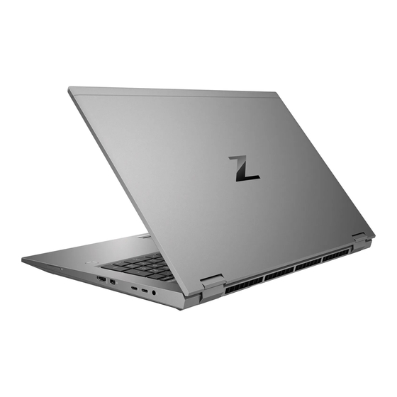
Components Right Use the illustration and table to identify the components on the right side of the computer. Table 2-1 Right-side components and their descriptions Component Description Memory card reader Reads optional memory cards that store, manage, share, or access information. To insert a card: Hold the card label-side up, with the connectors facing the computer. -
Page 20: Left
Table 2-1 Right-side components and their descriptions (continued) Component Description USB Type-C® Thunderbolt™ ports with HP Sleep Connect USB devices, provide high-speed data transfer, and and Charge (2) charge small devices, even when the computer is off. – and –... -
Page 21: Display
Regulatory, Safety, and Environmental Notices. To access this guide: ▲ Type HP Documentation in the taskbar search box, and then select HP Documentation. NOTE: When a device is connected to the jack, the computer speakers are disabled. - Page 22 For wireless regulatory notices, see the section of the Regulatory, Safety, and Environmental Notices that applies to your country or region. To access this guide: Type HP Documentation in the taskbar search box, and then select HP Documentation. ▲ Chapter 2 Components...
-
Page 23: Keyboard Area
Keyboard area ENWW Keyboard area... -
Page 24: Touchpad
Touchpad Chapter 2 Components ENWW... -
Page 25: Touchpad Settings
Touchpad settings Adjusting touchpad settings Follow these steps to adjust the touchpad settings and gestures. Use these steps to adjust touchpad settings and gestures. Type touchpad settings in the taskbar search box, and then press enter. Choose a setting. Turning on the touchpad Follow these steps to turn on the touchpad. -
Page 26: Bottom
For wireless regulatory notices, see the section of the Regulatory, Safety, and Environmental Notices that applies to your country or region. To access this guide: ▲ Type HP Documentation in the taskbar search box, and then select HP Documentation. Bottom Use the illustration and table to identify the bottom components. -
Page 27: Top Cover
Table 2-5 Bottom components and their descriptions Component Description Vent Enables airflow to cool internal components. NOTE: The computer fan starts up automatically to cool internal components and prevent overheating. It is normal for the internal fan to cycle on and off during routine operation. -
Page 28: Labels
Your service label will resemble one of the following examples. Refer to the illustration that most closely matches the service label on your computer. Table 2-8 Service label components and their descriptions Component HP product name Model name Warranty period Product ID Serial number... -
Page 29: Hp Tamperlock
The application is preset to disabled. The customer must enable this application in the BIOS, where it is called Smart Cover. If the customer enables HP TamperLock and sends in the computer for repair, the repair center will not be able to repair it. The Call Center will receive the following message: This product is equipped with Smart Cover (Tamper Detection password feature.) Ensure that the customer has... -
Page 30: Inserting A Sim Card In The Service Bay
the repair and potentially result in a billable event. If the computer does not boot or the customer is not able to check in and disable the feature, continue with normal procedures to replace the system board. Inserting a SIM card in the service bay To insert a SIM card, follow these steps. - Page 31 Slide the SIM tray cover to the right (1), open the cover (2), and then insert the SIM card into the SIM tray (3). NOTE: The SIM card in your computer might look slightly different from the illustration in this section. NOTE: To properly insert the SIM card, match the angled edge of the card with the triangle on the...
- Page 32 Chapter 2 Components ENWW...
-
Page 33: Illustrated Parts Catalog
To identify the computer major components, use this illustration and table. NOTE: HP continually improves and changes product parts. For complete and current information about supported parts for your computer, go to http://partsurfer.hp.com, select your country or region, and then follow the on-screen instructions. NOTE: Details about your computer, including model, serial number, product key, and length of warranty, are on the service tag at the bottom of your computer. - Page 34 Table 3-1 Computer major component descriptions and part numbers Item Component Spare part number 43.9 cm (17.3 in) display assembly: Chapter 3 Illustrated parts catalog ENWW...
- Page 35 Table 3-1 Computer major component descriptions and part numbers (continued) Item Component Spare part number UHD (3840×1980), Dream Vision, 550 touchscreen display assembly with webcam and infrared M20125-001 sensor; typical brightness: 400 nits UHD (3840×1980), Dream Vision, 550 touchscreen display assembly with webcam; typical brightness: M20124-001 400 nits UHD (3840×1980), Dream Vision, 550 touchscreen display assembly;...
- Page 36 Table 3-1 Computer major component descriptions and part numbers (continued) Item Component Spare part number For use in Romania M20128-271 For use in Russia M20128-251 For use in Saudi Arabia M20128-171 For use in Slovenia M20128-BA1 For use in South Korea M20128-AD1 For use in Spain M20128-071...
- Page 37 Table 3-1 Computer major component descriptions and part numbers (continued) Item Component Spare part number Equipped with an Intel Xeon W-10885M processor and the Windows 10 operating system for use on M20105-601 computer models with WWAN capability Equipped with an Intel Xeon W-10885M processor and a non-Windows operating system for use on M20105-001 computer models with WWAN capability Equipped with an Intel Xeon W-10885M processor and the Windows 10 operating system for use on...
- Page 38 Table 3-1 Computer major component descriptions and part numbers (continued) Item Component Spare part number Equipped with an Intel Core i5-10300H processor and a non-Windows operating system for use on M31400-001 computer models with WWAN capability Equipped with an Intel Core i5-10300H processor and the Windows 10 operating system for use on M20099-601 computer models without WWAN capability Equipped with an Intel Core i5-10300H processor and a non-Windows operating system for use on...
- Page 39 Table 3-1 Computer major component descriptions and part numbers (continued) Item Component Spare part number 256 GB, M.2 2280, PCIe-3×4, SS with TLC L85350-001 256 GB, M.2 2280, PCIe, NVMe, SED with TLC M07245-001 Solid-State Drive/Memory Module Thermal Pad Kit M29534-001 Solid-State Drive Hardware Kit (not illustrated, includes copper plate and support plate) M20090-001...
-
Page 40: Mass Storage Devices
Table 3-1 Computer major component descriptions and part numbers (continued) Item Component Spare part number (23) Bottom case M20092-001 (24) Service cover M23347-001 Mass storage devices To identify the mass storage devices, use this illustration and table. Table 3-2 Mass storage device descriptions and part numbers Item Component Spare part number... -
Page 41: Miscellaneous Parts
200 W AC adapter (PFC, RC, ultraslim barrel, 3 pin, 4.5 mm) L74881-001 150 W HP Smart adapter (PFC, slim barrel, 4.5 mm) L32661-001 120 W HP Smart adapter (PFC, RC, slim barrel, 4.5 mm) L41856-001 Bracket Kit (includes fingerprint bracket, memory module cover, solid-state drive cover, and switch spring) M20094-001... - Page 42 Table 3-4 Miscellaneous part descriptions and part numbers (continued) Component Spare part number Plastics Kit (includes display hinge covers, fingerprint blank bezel, SD card slot bezel, and webcam blank M20093-001 bezel) Power cord (C13, 1.0 m, premium with tag): For use in Australia 100661-021 For use in Denmark 130627-014...
- Page 43 Table 3-4 Miscellaneous part descriptions and part numbers (continued) Component Spare part number For use in the United Kingdom L30781-001 Rubber Kit (includes display hinge rubber caps, microphone rubber cover, and WWAN module rubber cover) M20114-001 Screw Kit M20118-001 ENWW Miscellaneous parts...
- Page 44 Chapter 3 Illustrated parts catalog ENWW...
-
Page 45: Removal And Replacement Procedures Preliminary Requirements
Removal and replacement procedures preliminary requirements Use this information to properly prepare to disassemble and reassemble the computer. Tools required You need the following tools to complete the removal and replacement procedures: Tweezers ● ● Nonconductive, nonmarking pry tool Magnetic Phillips P1 screwdriver ●... -
Page 46: Service Considerations
Service considerations The following sections include some of the considerations that you must keep in mind during disassembly and assembly procedures. NOTE: As you remove each subassembly from the computer, place the subassembly (and all accompanying screws) away from the work area to prevent damage. Plastic parts Using excessive force during disassembly and reassembly can damage plastic parts. - Page 47 Cover the workstation with approved static-shielding material. ● Use a wrist strap connected to a properly grounded work surface and use properly grounded tools and ● equipment. Use conductive field service tools, such as cutters, screw drivers, and vacuums. ● When fixtures must directly contact dissipative surfaces, use fixtures made only of static-safe materials.
-
Page 48: Electrostatic Discharge Information
Electrostatic discharge information A sudden discharge of static electricity from your finger or other conductor can destroy static-sensitive devices or microcircuitry. Often the spark is neither felt nor heard, but damage occurs. An electronic device exposed to electrostatic discharge (ESD) might not appear to be affected at all and can work perfectly throughout a normal cycle. -
Page 49: Preventing Electrostatic Damage To Equipment
Preventing electrostatic damage to equipment Many electronic components are sensitive to ESD. Circuitry design and structure determine the degree of sensitivity. The following packaging and grounding precautions are necessary to prevent static electricity damage to electronic components. To avoid hand contact, transport products in static-safe containers such as tubes, bags, or boxes. ●... -
Page 50: Recommended Materials And Equipment
● foam. Use field service tools, such as cutters, screwdrivers, and vacuums, that are conductive. ● Recommended materials and equipment HP recommends certain materials and equipment to prevent static electricity. ● Antistatic tape Antistatic smocks, aprons, or sleeve protectors ●... - Page 51 Store reusable ESD-sensitive parts from assemblies in protective packaging or nonconductive foam. ● Use transporters and conveyors made of antistatic belts and roller bushings. Be sure that mechanized ● equipment used for moving materials is wired to ground and that proper materials are selected to avoid static charging.
- Page 52 Chapter 4 Removal and replacement procedures preliminary requirements ENWW...
-
Page 53: Removal And Replacement Procedures For Customer Self-Repair Parts
Removal and replacement procedures for Customer Self-Repair parts This chapter provides removal and replacement procedures for Customer Self-Repair parts. NOTE: The Customer Self-Repair program is not available in all locations. Installing a part that is not supported by the Customer Self-Repair program can void your warranty. Check your warranty to determine whether Customer Self-Repair is supported in your location. -
Page 54: Component Replacement Procedures
NOTE: HP continually improves and changes product parts. For complete and current information about supported parts for your computer, go to http://partsurfer.hp.com, select your country or region, and then follow the on-screen instructions. You must remove, replace, or loosen as many as 21 screws when you service Customer Self-Repair parts. Make special note of each screw size and location during removal and replacement. -
Page 55: Battery
Slide the service cover (4) toward the front of the computer, and then remove the service cover. To replace the service cover, reverse the removal procedures. Battery To remove the battery, use this procedure and illustration. Table 5-2 Battery description and part number Description Spare part number 8 cell, 94 Whr battery... -
Page 56: Solid-State Drives 3 And 4
WARNING! To reduce potential safety issues, use only the user-replaceable battery provided with the computer, a replacement battery provided by HP, or a compatible battery purchased from HP. IMPORTANT: Removing a battery that is the sole power source for the computer can cause loss of information. - Page 57 Table 5-3 Solid-state drive description and part number (continued) Description Spare part number 256 GB, M.2 2280, PCIe-3×4, SS with TLC L85350-001 256 GB, M.2 2280, PCIe, NVMe, SED with TLC M07245-001 Before removing solid-state drive 3 and 4, follow these steps: Prepare the computer for disassembly (Preparation for disassembly on page 66).
-
Page 58: Hard Drive
Remove the carrier (3). Reverse this procedure to install solid-state drives 3 and 4 and the solid-state drive carrier. Hard drive To remove the hard drive, use these procedures and illustrations. Table 5-4 Hard drive, hard drive bracket and hard drive cable descriptions and part numbers Description Spare part number NOTE:... - Page 59 Loosen the three Phillips screws (1) that secure the hard drive to the computer. Swing the carrier bar (2) up and to the left to release the hard drive. Slide the hard drive (3) to the left, and then remove the hard drive from the computer. Reverse this procedure to install the hard drive.
-
Page 60: Wlan Module
Reverse this procedure to reassemble the hard drive. WLAN module To remove the WLAN module, use this procedure and illustration. Table 5-5 WLAN module descriptions and part numbers Description Spare part number Intel Wi-Fi 6 AX201 ax 2×2 + Bluetooth 5.0 MU-MIMO M.2 2230 non-vPro MIPI+BRI WW with 2 antennas L57250-001 Intel Wi-Fi 6 AX201 ax 2×2 + Bluetooth 5.0 MU-MIMO M.2 2230 vPro 160MHz MIPI + BRI WW with 2 antennas L57248-001... -
Page 61: Wwan Module
Remove the Phillips M2.0 × 2.9 screw (2), and then remove the WLAN module (3). NOTE: Models have either one or two WLAN antennas. On models with two antennas, the #1 WLAN antenna cable connects to the WLAN module #1 Main terminal. The #2 WLAN antenna cable connects to the WLAN module #2 Aux terminal. - Page 62 Table 5-6 WWAN module descriptions and part numbers Description Spare part number Intel XMM 7360 LTE-Advanced (Cat 9) L70670-001 IMPORTANT: To prevent an unresponsive system, replace the wireless module only with a wireless module authorized for use in the computer by the governmental agency that regulates wireless devices in your country or region.
-
Page 63: Solid-State Drive 2
If the WWAN antenna is not connected to the terminal on the WWAN module, a protective sleeve must be installed on the antenna connector, as shown in the following illustration. Reverse this procedure to install the WWAN module. Solid-state drive 2 To remove solid-state drive 2, use this procedure and illustration. - Page 64 Remove the cover (3) by sliding it to the left at an angle. The solid-state drive cover is included in the Bracket Kit, spare part number M20094-001. Chapter 5 Removal and replacement procedures for Customer Self-Repair parts ENWW...
-
Page 65: Memory Modules 2 And 4
Pull the drive away from the socket to remove it (1). Solid-state drives are designed with a notch (2) to prevent incorrect installation. A thermal pad services solid-state drive 2 and is located on the solid-state drive compartment cover. This pad should be inspected each time that the cover is removed. - Page 66 Table 5-8 Memory module descriptions and part numbers Description Spare part number 32 GB (2666 MHz, 1.2 V, DDR4) L50384-001 16 GB (2666 MHz, 1.2 V, DDR4, ECC) L24981-001 16 GB (2666 MHz, 1.2 V, DDR4) 937438-950 8 GB (3200 MHz, 1.2 V, DDR4) L46598-001 8 GB (2666 MHz, 1.2 V, DDR4, ECC) L24983-001...
- Page 67 Spread the two retention clips outward (1) until the memory module tilts up at a 45° angle, and then remove the module (2). Use the same procedure to remove all memory modules. IMPORTANT: To prevent damage to the memory module, hold the memory module by the edges only. Do not touch the components on the memory module.
-
Page 68: Keyboard
Press down on the module until the side retention clips snap into place (3). Keyboard To remove the keyboard, use this procedure and illustration. Table 5-9 Keyboard description and part number For use in country/region Spare part number For use in country/region Spare part number Keyboard with backlight, clickpad, and pointing stick (includes backlight cable, clickpad cable, keyboard cable, and pointing stick cable): For use in Belgium... - Page 69 Table 5-9 Keyboard description and part number (continued) For use in country/region Spare part number For use in country/region Spare part number For use in Italy M20128-061 For use in Turkey-F M20128-541 For use in Japan M20128-291 For use in Ukraine M20128-BD1 For use in Latin America M20128-161...
- Page 70 Detach the pointing stick cable (4) from the top cover. (The pointing stick cable is attached to the top cover with double-sided adhesive.) Open the computer. Rest the open computer on its left side. Chapter 5 Removal and replacement procedures for Customer Self-Repair parts ENWW...
- Page 71 Insert a keyboard release tool or other thin, plastic tool through the KB release opening near the fan and release the keyboard by pressing on its back. Rest the open computer right side up with the front toward you. Swing the top edge of the keyboard (1) up and forward until it rests upside down on the top cover. Detach the backlight cable (2) from the top cover.
-
Page 72: Memory Modules 1 And 3
Remove the keyboard (6). Reverse this procedure to install the keyboard. Memory modules 1 and 3 To remove memory modules 1 and 3, use this procedure and illustration. Table 5-10 Memory module descriptions and part numbers Description Spare part number 32 GB (2666 MHz, 1.2 V, DDR4) L50384-001 16 GB (2666 MHz, 1.2 V, DDR4, ECC) - Page 73 Prepare the computer for disassembly (Preparation for disassembly on page 66). Remove the service cover (Service cover on page 40). Remove the battery (see Battery on page 41). Remove the keyboard (see Keyboard on page 54). If you are replacing memory modules 1 and 3, remove the existing memory module: Remove the two Phillips M2.0 ×...
- Page 74 Remove the cover (3) by sliding it forward and then lifting it up. Thermal pads service memory modules 1 and 3 and are located on the memory module compartment cover. These pads should be inspected each time that the cover is removed. These pads are intended to be reused if they are not damaged.
- Page 75 Spread the two retention clips outward (1) until the memory module tilts up at a 45° angle, and then remove the module (2). Use the same procedure to remove all memory modules. IMPORTANT: To prevent damage to the memory module, hold the memory module by the edges only. Do not touch the components on the memory module.
-
Page 76: Solid-State Drive 1
Press down on the module until the side retention clips snap into place (3). Solid-state drive 1 To remove solid-state drive 1, use this procedure and illustration. Table 5-11 Solid-state drive description and part number Description Spare part number 1 TB, M.2 2280, PCIe, NVMe-3×4, SS with TLC L85348-001 512 GB, M.2 2280, PCIe-3×4, SS with TLC L85360-001... - Page 77 Remove the cover (3) by sliding it to the right at an angle. A thermal pad services solid-state drive 1 and is located on the solid-state drive cover. This pad should be inspected each time that the cover is removed. This pad is intended to be reused if it is not damaged. If this pad is damaged and any residue remains on the solid-state drive (1) or the cover (2), it should be thoroughly removed and replaced.
- Page 78 Pull the drive away from the socket to remove it (1). Solid-state drives are designed with a notch (2) to prevent incorrect installation. To install the solid-state drive, reverse the removal procedures. Chapter 5 Removal and replacement procedures for Customer Self-Repair parts ENWW...
-
Page 79: Removal And Replacement Procedures For Authorized Service Provider Parts
Removal and replacement procedures for authorized service provider parts This chapter provides removal and replacement procedures for authorized service provider parts. IMPORTANT: Components described in this chapter should be accessed only by an authorized service provider. Accessing these parts can damage the computer or void the warranty. NOTE: Details about your computer, including model, serial number, product key, and length of warranty, are on the service tag at the bottom of your computer. -
Page 80: Component Replacement Procedures
NOTE: HP continually improves and changes product parts. For complete and current information about supported parts for your computer, go to http://partsurfer.hp.com, select your country or region, and then follow the on-screen instructions. You must remove, replace, or loosen as many as 84 screws when you service the parts described in this chapter. - Page 81 Remove the nine Phillips M2.5 × 6.0 (2) screws that secure the bottom case to the computer. Remove the four Torx8 M2.5 × 3.5 (3) screws that secure the bottom case to the computer. Insert a case utility tool (1) or similar thin plastic tool in the display hinge area and separate the bottom case from the top cover.
-
Page 82: Sd Card Board Cable
SD card board cable To remove the SD card board cable, use this procedure and illustration. The SD card board cable is available in the Cable Kit, spare part number M20105-001. Before removing the SD card board cable, follow these steps: Prepare the computer for disassembly (Preparation for disassembly on page 66). -
Page 83: Sd Card Board
Reverse this procedure to install the SD card board cable. SD card board To remove the SD card board, use this procedure and illustration. NOTE: The SD card board spare part kit includes SD card board. Table 6-2 SD card board description and part number Description Spare part number SD card board... -
Page 84: Fingerprint Reader Module Cable
Remove the SD card board (5) and cable Reverse this procedure to install the SD card board and cable. Fingerprint reader module cable To remove the fingerprint reader module cable, use this procedure and illustration. The fingerprint reader module cable is available in the Cable Kit, spare part number M20105-001. Before removing the fingerprint reader module cable, follow these steps: Prepare the computer for disassembly (Preparation for disassembly on page... -
Page 85: Fingerprint Reader Module
Remove the fingerprint reader module cable (3). Reverse this procedure to install the fingerprint reader module cable. Fingerprint reader module To remove the fingerprint reader module, use this procedure and illustration. Table 6-3 Fingerprint reader module description and part number Description Spare part number Fingerprint reader module... -
Page 86: Hard Drive Cable
Remove the fingerprint reader module: Release the ZIF connector (1) to which the fingerprint reader module cable is connected, and then disconnect the fingerprint reader module cable from the system board. Remove the Phillips M2.0 × 2.9 broad head screw (2) that secures the fingerprint reader module to the top cover. -
Page 87: Touchpad Cable
Keyboard (see Keyboard on page Bottom case (see Bottom case on page Remove the hard drive cable: Disconnect the hard drive cable (1) from the system board. Release the hard drive cable from the retention clips (2) built into the top cover. Remove the two Phillips M2.5 ×... -
Page 88: Touchpad
Keyboard (see Keyboard on page Bottom case (see Bottom case on page Remove the touchpad cable: Detach the touchpad cable (1) from the top cover. (The touchpad cable is attached to the top cover with double-sided adhesive.) Release the ZIF connector (2) to which the touchpad cable is connected, and then disconnect the touchpad cable from the system board. -
Page 89: Nfc Module Cable
Prepare the computer for disassembly (Preparation for disassembly on page 66). Remove the service cover (Service cover on page 40), and then remove the following components: Battery (see Battery on page Solid-state drives 3 and 4 (see Solid-state drives 3 and 4 on page Solid-state drive carrier (see Solid-state drives 3 and 4 on page Hard drive (see... -
Page 90: Nfc Module
Before removing the NFC module cable, follow these steps: Prepare the computer for disassembly (Preparation for disassembly on page 66). Remove the service cover (Service cover on page 40), and then remove the following components: Battery (see Battery on page Solid-state drives 3 and 4 (see Solid-state drives 3 and 4 on page Solid-state drive carrier (see... - Page 91 NOTE: The NFC module spare part kit includes NFC module. Table 6-5 NFC module description and part number Description Spare part number NFC module M17065-001 NOTE: The NFC module spare part kit does not include the NFC module cable. The NFC module cable is available in the Cable Kit, spare part number M20105-001.
-
Page 92: Card Reader Board
Detach the NFC module (4) from the top cover. (The NFC module is attached to the top cover with double- sided adhesive.) Reverse this procedure to install the NFC module and cable. Card reader board To remove the card reader board, use this procedure and illustration. Table 6-6 Card reader board description and part number Description... -
Page 93: Fan/Heat Sink Assembly
Release the ZIF connector (1) to which the card reader board cable is connected, and then disconnect the card reader board cable from the system board. Detach the card reader board cable (2) from the top cover. (The card reader board cable is attached to the top cover with double-sided adhesive.) Remove the four Phillips M2.0 ×... - Page 94 Prepare the computer for disassembly (Preparation for disassembly on page 66). Remove the service cover (Service cover on page 40), and then remove the following components: Battery (see Battery on page Solid-state drives 3 and 4 (see Solid-state drives 3 and 4 on page Solid-state drive carrier (see Solid-state drives 3 and 4 on page Hard drive (see...
- Page 95 Remove the fan/heat sink assembly (8) by sliding it up and forward at an angle. ENWW Component replacement procedures...
- Page 96 Thoroughly clean the thermal material from the surfaces of the fan/heat sink assembly and the system board components each time the fan/heat sink assembly is removed. Replacement thermal material is included with the fan/heat sink assembly and system board spare part kits. The following illustrations show the replacement thermal material locations.
-
Page 97: 43.9 Cm (17.3 In ) Display Assembly
43.9 cm (17.3 in ) display assembly To remove and disassemble the display assembly, use these procedures and illustrations. The display assembly is available as both a full hinge-up assembly and at the the subcomponent level. Full hinge-up assembly spare part information is presented in the following table. Subcomponent level spare part information is available in the subcomponent level disassembly subsection. - Page 98 Remove the WLAN module Mylar shield (1) and the WWAN module Mylar shield. The WLAN/WWAN module Mylar shields are included in the Mylar Kit, spare part number M23349-001. Disconnect the wireless antenna cables (2) from the WLAN module and the WWAN module. The #1/white WLAN antenna cable connects to the WLAN module #1/Main terminal.
-
Page 99: Beam Connector
Remove the nine Phillips M2.5 × 6.0 screws (1) that secure the display assembly to the computer. Swing the top edge of the display assembly (1) away from the top cover. (The top cover disengages from the display assembly hinges.) Separate the display assembly (2) from the top cover. - Page 100 Table 6-9 Beam connector description and part number Description Spare part number Beam connector (includes plastic installation tool and replacement thermal material) M25737-001 The beam connector ships attached to a plastic installation tool which is packaged inside a sealed plastic container. Extra precautions have been taken to prevent any unnecessary contact with the pins on the beam connector, which are delicate.
-
Page 101: Graphics Card
Align the pins on the replacement beam connector with the holes in the system board, and then carefully install the beam connector (1) onto the socket on the system board. Without moving the beam connector, press the installation tool release tabs (2) together to release the beam connector. - Page 102 Table 6-10 Graphics card descriptions and part numbers Description Spare part number AMD RX 5500M graphics card with 4 GB integrated memory M17050-001 AMD W 5500M graphics card with 4 GB integrated memory M17049-001 AMD Thermal Pad Kit M29533-001 NVIDIA RTX 3000 graphics card with 6 GB integrated memory M17051-001 NVIDIA RTX 4000 graphics card with 8 GB integrated memory M17052-001...
-
Page 103: System Board
Slide the graphics card (2) away from the system board slot and remove it. Reverse this procedure to install the graphics card. System board To remove the system board, use these procedures and illustrations. Table 6-11 System board descriptions and part numbers Description Spare part number... - Page 104 Table 6-11 System board descriptions and part numbers (continued) Description Spare part number Equipped with an Intel Core i7-10850H processor and the Windows 10 operating system for use on computer models M31403-601 with WWAN capability Equipped with an Intel Core i7-10850H processor and a non-Windows operating system for use on computer models M31403-001 with WWAN capability Equipped with an Intel Core i7-10850H processor and the Windows 10 operating system for use on computer models...
- Page 105 Keyboard (see Keyboard on page Memory module compartment cover for memory module 1 and 3 (see Memory modules 1 and 3 on page Solid-state drive 1 (see Solid-state drive 1 on page Bottom case (see Bottom case on page When you replace the system board, be sure to remove the following components (as applicable) from the defective system board and install them on the replacement system board: WLAN module (see WLAN module on page...
- Page 106 Release the webcam cable and the wireless antenna cables from the retention clips (3) built into the right fan. Disconnect the webcam cable (4) and the display panel cable (5) from the system board: Release the display panel cable from the retention clips (6) built into the left fan. Disconnect the following cables from the system board: NFC module cable (ZIF) (7) ●...
- Page 107 Lift the front/right edge of the system board (1) until it rests at an angle. When the system board is released, it is disconnected (2) from the I/O board (2). ENWW Component replacement procedures...
-
Page 108: Rtc Battery
Remove the system board (3). A thermal pad services the chip (1) on the top of the system board and is located on the heat sink (2) built into the top cover. This pad should be inspected each time that the cover is removed. This pad is intended to be reused if it is not damaged. -
Page 109: I/O Board
Before removing the RTC battery, follow these steps: Prepare the computer for disassembly (Preparation for disassembly on page 66). Remove the service cover (Service cover on page 40), and then remove the following components: Battery (see Battery on page Solid-state drives 3 and 4 (see Solid-state drives 3 and 4 on page Solid-state drive carrier (see Solid-state drives 3 and 4 on page... - Page 110 Before removing the I/O board, follow these steps: Prepare the computer for disassembly (Preparation for disassembly on page 66). Remove the service cover (Service cover on page 40), and then remove the following components: Battery (see Battery on page Solid-state drives 3 and 4 (see Solid-state drives 3 and 4 on page Solid-state drive carrier (see Solid-state drives 3 and 4 on page...
-
Page 111: Speakers
Remove the I/O board (3). When removing or replacing the I/O board, make sure the security lock bracket is installed correctly, as shown in the following illustration. The security lock bracket is included in the Bracket Kit, spare part number M20094-001. Reverse this procedure to install the I/O board. - Page 112 Before removing the speakers, follow these steps: Prepare the computer for disassembly (Preparation for disassembly on page 66). Remove the service cover (Service cover on page 40), and then remove the following components: Battery (see Battery on page Solid-state drives 3 and 4 (see Solid-state drives 3 and 4 on page Solid-state drive carrier (see Solid-state drives 3 and 4 on page...
-
Page 113: Troubleshooting Guide
Troubleshooting guide This chapter primarily focuses on troubleshooting HP Mobile Workstations. The information is provided so that you can solve problems yourself or at least narrow down the number of possible causes. Based on some of the most common symptoms, this chapter identifies logical steps and available resources or tools for resolving an issue. - Page 114 Provides important support, such as warranty, support https://support.hp.com/us-en/contact-hp cases, drivers, Customer Advisories, Customer and Security Bulletins, and Product Change Notices. Subscribers Choice Allows you to sign up for HP product updates. http://www8.hp.com/us/en/subscribe/ HP Support Forums Provide discussions about HP products and issues. http://h30434.www3.hp.com/psg/...
-
Page 115: General Troubleshooting Steps
Proceed through the steps in the following table until the issue is resolved, and then move on to the next step that is relevant to the issue. For example, if you resolve a memory issue using the HP PC Diagnostics (UEFI) tool in step 6, you can then move on to step 10 to reseat the memory into its memory slot. -
Page 116: Identify The Issue
Identify the issue Use these guidelines to correctly determine the problem. 102 Chapter 7 Troubleshooting guide ENWW... -
Page 117: Understand The Issue
Power-On Self-Test (POST) verifies that hardware components (such as processor, hard drive, memory) are functional. When POST is complete, the HP logo appears briefly and then disappears. If there are errors, the computer may exhibit blinking lights and POST error messages, and so on. -
Page 118: Failure Classification
Failure classification Failure classification is a breakdown of different types of failures and symptoms that could occur during the boot-up sequence. Failure classification by boot-up sequence on page 104 Failure classification by hardware devices on page 105 represent the failure classification for common notebook failures. Failure classification by boot-up sequence on page 104 categorizes failures by the boot-up sequence. - Page 119 No wake up on page 138 on page 130 Unresponsive on page 139 Burnt smell on page 130 Slow performance on page 140 HP Smart Adapter warning message on page 140 Incorrect time and date on page 141 a,b,c similar symptoms Failure classification by hardware devices To determine failure by device, use this table.
-
Page 120: Examine The Environment
Table 7-5 Failure classification by hardware devices 4. Display 5. I/O devices 6. Storage 7. Mechanical Display anomalies Keyboard on page 150 Hard drive or solid-state Noise (sound) on page 164 on page 143 drive not recognized Keyboard pointing stick Fan runs constantly on page 159 Dead pixel on page 145... -
Page 121: Update Bios And Drivers
Note that some customer company policies prohibit updates. Check your company policy before taking action. The updates may include fixes for your computer issues, and they may also enhance system performance. HP continually improves the update process to make it easier. You can update the BIOS locally through a manual process, through an automatic installation, or through a remote installation on multiple units. -
Page 122: Analyze The Issue
5. Remove or uninstall recently added hardware, software HP has designed this computer and validated it using a full-range hardware and software qualification matrix. If an issue appears to have started recently, it may be related to the recent addition of hardware or software. -
Page 123: Hp Hardware Diagnostics And Tools
6. HP Hardware Diagnostics and Tools HP offers diagnostics and tools to diagnose hardware failure. This section describes how to use some of these tools. Make sure to check for the latest versions before use. HP PC Hardware Diagnostics (UEFI) HP PC Hardware Diagnostics is a Unified Extensible Firmware Interface (UEFI) that allows you to run diagnostic tests to determine whether the computer hardware is functioning properly. -
Page 124: Hp Bios Configuration Utility (Bcu)
HP BIOS Configuration Utility (BCU) HP BCU is a free utility that captures the BIOS settings and their values. This tool provides a text file of the computer’s BIOS configuration. This file can help identify any settings that may be contributing to an issue. -
Page 125: Hp Image Diagnostic Tool
The report may assist you with diagnostics and solutions to problems you encounter. HP Thermal Monitor You can use HP Thermal Monitor to stress the processor and GPU and monitor the temperature values of various components in the system. -
Page 126: Status Lights, Blinking Light Codes, Troubleshooting Lights, And Post Error Messages
Off: The battery is fully charged. Front hard drive light Blinking white: The hard drive is being accessed. Amber: HP 3D DriveGuard has temporarily parked the hard drive. Rear AC adapter light White: The computer is connected to external power. -
Page 127: Post Error Messages
● BIOS Mass storage devices ● ● Fans The following table describes errors encountered during HP PC Hardware Diagnostics (UEFI). Table 7-8 System diagnostics failure codes and actions to address the failure Test description Failure description Error code Suggested user actions... - Page 128 Primary Battery Replace This message indicates that the primary battery has very low capacity. Search for support documentation at http://www.hp.com/support for details on using the HP Support Assistant to verify the battery capacity and, if necessary, order a replacement. Wireless Modules Not installed or responding Reseat the wireless LAN adapter module and antennas.
-
Page 129: Resolve The Issue
Before performing a hard reset, you must disconnect or remove all peripheral devices. Start and test the computer by itself, and if the problem is not resolved, reconnect one peripheral device at a time. To resolve the startup or operational problem, run HP Support Assistant, or manually install all updated drivers from Microsoft and HP. -
Page 130: Soft Reset (Default Settings)
If a startup menu appears, use the arrow keys to select Start Windows Normally, and then press the enter key. After reconnecting each of the peripheral devices, run Windows Update and HP Support Assistant to update all device drivers. CMOS refers to the battery-powered semiconductor chip located on computer's system board. Notebooks store low-level settings like the system time and hardware settings in CMOS. - Page 131 For field replaceable units (FRUs), authorized service providers can try the following steps. For more information, Removal and replacement procedures for authorized service provider parts on page ● Reseating the fan cable can fix POST error 90B (no fan detected) issue (see POST error messages and user actions on page 171).
-
Page 132: Test With Minimum Configuration
NOTE: This step is to be used by authorized service providers only. HP will not honor the warranty for a system tested with the system board removed without the heat sink or fan. -
Page 133: Safe Mode
Testing with a verified working AC adapter can identify an error caused by a faulty one. Similarly, testing with a verified working operating system can determine bad behaviors of the current operating system. See Non HP diagnostics tools on page 111 for instructions about obtaining and using a Windows-To-Go USB. -
Page 134: Verify Solution
Explain to the customer why the issue occurred and what was done to resolve it. If the solution you used was in an HP public document, provide the document information to the customer, letting them know they can locate it on http://www.hp.com. Also, tell them that there are other solutions available on the website. -
Page 135: Helpful Hints
These steps provide simple, useful checks that you can perform when troubleshooting. TIP: If you have installed an operating system other than the factory-installed operating system, go to http://www.hp.com/go/quickspecs and verify that it is supported on your system. Be sure that the computer is plugged into a working AC outlet. -
Page 136: Consulting With Hp Service
Press the touchpad On/Off button light. If the light toggles on or off, the touchpad is likely operating correctly. Consulting with HP Service If further HP support is required, this information may be requested when you call. So it may be helpful to take notes. Technical support registration number (if applicable) ●... -
Page 137: Common Issues And Possible Solutions
Common issues and possible solutions This section contains common issues, symptoms, and a series of tables that describe possible solutions to issues from Failure Classification tables. The following sections identify the issue with symptoms and solutions to resolve an issue. ENWW Common issues and possible solutions 123... -
Page 138: Power-On Issues
Power-on issues Use the following sections to troubleshooting power issues. No power When a unit experiences no power, there are several contributing factors to consider. Be sure to consider all symptoms related to this behavior when troubleshooting. Table 7-9 Issues, possible causes, and fixes Items Procedures Symptoms... - Page 139 Replace new power connector cable (if the cable exists and is defective) To isolate faulty power connector cable and power button, technicians can short power-on pads or pins to turn on the computer. Contact HP Engineering for this information. Verify blinking lights (7.
-
Page 140: Intermittent Power-On, Shutdown, Reboot
Table 7-9 Issues, possible causes, and fixes (continued) Items Procedures system) on page 119, 13. Replace the system board on page 119) by removing nonessential parts. If the computer still does not boot, replace system board. Tips Computer automatically boots without pressing power button when the RTC 3 V battery is removed. -
Page 141: Ac Adapter Issue
Verify that the AC adapter works on a verified working computer. If the computer operates normally, there is no problem with the adapter. See HP Smart Adapter warning message on page 140 for further information. -
Page 142: Battery Not Recognized, Not Charging
If there is still no rear power light or no boot, replace the AC adapter. Tips The HP Smart AC adapter has a special pin in the middle, called the ID pin, for power rating and throttling. If this pin is broken, the rear power light turns on, but the power button and front power lights blink continuously, and the computer does not turn on. - Page 143 (6. HP Hardware Diagnostics and Tools on page 109) HP PC Hardware Diagnostics (UEFI) is a good tool to use to isolate and determine faulty battery, especially for quickly discharging (short life) battery. Verify that battery is recognized and charging.
-
Page 144: Battery Discharges Too Fast
To conserve battery power, turn off Wireless On-Off button and other peripherals and USB devices, applications, processes (in Task Manager) when not in use; also, reduce screen brightness. Follow HP instructions about how to maintain battery and increase battery life. Also reference http://support.hp.com/us-en/document/c01297640? jumpid=hpr_r1002_usen_link3. - Page 145 Further inspection on components Inspect further sources internally after disassembling chassis, such as burnt or damaged components. If the issue persists, replace boards, AC adapter, and battery for safety concern, and report issues to HP. ENWW Common issues and possible solutions 131...
-
Page 146: Post
Perform hardware reset (8. Hard reset on page 115) and verify that HP Logo is presented correctly on display screen when pressing f10. Test with external monitor via VGA port (or DisplayPort, HDMI, or other). Press power button and close the computer lid to force video output to external video. -
Page 147: Blinking Lights
Table 7-15 Issues, possible causes, and fixes (continued) Items Procedures Reseat display cable connection on system board. Reseat display cable connection on display panel side. Examine and reseat major components, such as hard drive and memory. Test with minimum configuration (11. -
Page 148: Bios Password
Your BIOS settings may be managed by a BIOS administrator password setup. If you lost or forgot the user password, contact your IT personnel. Reference HP F10 Setup Overview http://h10032.www1.hp.com/ctg/Manual/c04460979 http://h10032.www1.hp.com/ctg/Manual/c04685655 2015 Business PC models: see the HP PC BIOS F10 Setup Guide at http://support.hp.com. 134 Chapter 7 Troubleshooting guide ENWW... -
Page 149: Performance (Os)
HP ships and supports Windows 7 with BIOS Legacy boot mode and Windows 8 and 10 with BIOS UEFI boot mode. Therefore, HP recommends that you switch BIOS boot mode from Legacy to UEFI Native for clean Windows 8 or 10 installations, or to UEFI Hybrid (if available) for upgrading the option from Windows 7 to Windows 8 or 10. -
Page 150: Blue Screen
The following steps are for authorized providers or technicians. Thermal-related issue Verify thermal condition: Test fan using HP PC Hardware Diagnostics (UEFI) tool (6. HP Hardware Diagnostics and Tools on page 109) Check fan and connection. Reseat fan cable. -
Page 151: Electromagnetic Interference (Emi)
107). Roll back to previous version may be necessary. Go to safe mode to install drivers. Run Hardware Diagnostics (6. HP Hardware Diagnostics and Tools on page 109) to isolate hardware issue. Undo recent changes in Windows (5. Remove or uninstall recently added hardware, software on page 108). -
Page 152: No Wake Up
Table 7-21 Issues, possible causes, and fixes Items Procedures Symptoms Possible causes System locks up, freezes in certain Electromagnetic interference (EMI). physical area or location Troubleshooting steps (2. Examine the environment on page 106). Pay attention to external power source, high-frequency signals such as cell phones, microwave ovens. -
Page 153: Unresponsive
Table 7-22 Issues, possible causes, and fixes (continued) Items Procedures Troubleshooting steps Verify that front power light (7. Status lights, blinking light codes, troubleshooting lights, and POST error messages on page 112) is blinking (indicating Sleep state). Press power button to exit Sleep. Reset BIOS to default (associated with OS Power Management in Power Menu) (4. -
Page 154: Slow Performance
Perform disk defragmentation to consolidate fragmented data on the hard drive so it works more efficiently. Tips Routine maintenance for performance improvement on page 173). See http://windows.microsoft.com/en-us/windows-8/free-up-disk-space. http://windows.microsoft.com/en-us/windows/optimize-windows-better- performance#optimize-windows-better-performance=windows-vista. HP Smart Adapter warning message Use this information to troubleshoot power adapter warning messages. 140 Chapter 7 Troubleshooting guide ENWW... -
Page 155: Incorrect Time And Date
Contact HP for configuration details. Note HP Smart AC adapter warning message: informs you that as power demands increase, the notebook may not perform at full capacity, which may result in longer battery-charging time. In cases of extreme power demands, the system may also throttle back the processor, or with systems that have a discrete video subsystem, a video balance mode may occur to further balance the power needs of the system. -
Page 156: Display
Display Use these sections to troubleshoot display issues. 142 Chapter 7 Troubleshooting guide ENWW... -
Page 157: Display Anomalies
Display anomalies The display panel is a field-replaceable unit (FRU) and must be replaced by only authorized technicians. However, HP highly recommends that users and technicians observe symptoms and use the HP PC Hardware Diagnostics (UEFI) tool before any replacement. -
Page 158: Quick Check
● Palette Check: to test the three video color components (red, green, blue) ● Dead Pixel Check: to check dead pixels in eight different colors (Dead Pixel Check is available with the HP PC ● Diagnostics 3-in-1 USB Key tool) Review the video troubleshooting in the following Display section for specific issues and possible solutions. -
Page 159: Dead Pixel
Use an external monitor with higher resolution. Test with external monitor using HDMI or HP port. Press the power button and close the computer lid to force video output to external video. If there is still no video, contact support. -
Page 160: Displayport/Vga
Table 7-29 Issues, possible causes, and fixes Items Procedures Symptom Possible causes No image on external External monitor, resolution, display configuration, drivers. monitor Troubleshooting steps Be sure external monitor is compatible with the computer. Be sure that external monitor is turned on. Press any key to exit the power-saving mode. -
Page 161: No Or Bad External Video Via Docking
DisplayPort of the dock. If you still cannot update the dock, attempt to update it on a confirmed working notebook before having the dock replaced. Note See the technical white paper titled “Multiple displays on HP ZBook Mobile Workstations” from HP platform support website. Go to http://h20195.www2.hp.com/v2/getpdf.aspx/ 4aa5-2657enw. -
Page 162: Touch Screen
Table 7-32 Issues, possible causes, and fixes Items Procedures Symptoms Possible causes System works normally but the display Loose connection, display cable, display, graphics card. shows: Troubleshooting steps Missing or strange color ● Verify with external monitor Image distortion ● Use combination fn + f4 to enable output to external monitor. - Page 163 Sleep mode. Perform Microsoft System Restore, and restore to a time when the system was working. Perform HP System Recovery if none of the previous actions resolve the issue. References https://support.hp.com/us-en/document/c03488148 ENWW...
-
Page 164: I/O Devices
Make sure external devices are supported and compliant (for example, USB Type-C, Thunderbolt 3, PCI ● Express). If you have problems with external devices not provided by HP, contact device manufacturers for ● compatibility and latest drivers before troubleshooting (for example, USB devices, Thunderbolt devices, PCI express card reader, VGA, display, HDMI monitors, speakers). -
Page 165: Keyboard Pointing Stick
Table 7-34 Issues, possible causes, and fixes (continued) Items Procedures Verify whether keyboard flex cable is in good condition (no delamination or torn cable end, no missing or cracked tracks, pads). Verify that keyboard flex cable ends are fully inserted and aligned with connectors on system board, and those connector tabs are properly closed. -
Page 166: Touchpad
Install the latest touchpad driver. Adjust touchpad settings (Control Panel > Mouse). Test touchpad controller using the HP PC Hardware Diagnostics (UEFI) tool (f2> Component Tests > Mouse Test > Pointer Test & Drag and Drop Test). The following steps are for authorized service providers/technicians. -
Page 167: Network Connectivity Wireless (Wlan)
Table 7-38 Issues, possible causes, and fixes Items Procedures Symptoms Possible causes Unable to find networks (yellow bang) Network source, cable, connection, RJ-45 (network) jack, driver, settings. ● Connection dropouts ● Slow performance ● Troubleshooting steps Quick Check: verify the network status lights that supposed to flash when there is network activity. -
Page 168: Usb
Table 7-40 Issues, possible causes, and fixes (continued) Items Procedures Troubleshooting steps Update to the latest driver and utility. Check with network service provider for signal coverage. Be sure signal strength is good. Be sure that your service is active. The following steps are for authorized providers or technicians. -
Page 169: Smart Card Reader
Table 7-41 Issues, possible causes, and fixes Items Procedures Symptoms Possible causes USB devices are not recognized USB devices do not have the latest software drivers or port insufficient power, or the ● devices are not compliant. USB devices are not charging ●... -
Page 170: Speaker, Headphone - Audio Issues
Table 7-42 Issues, possible causes, and fixes (continued) Items Procedures Card Reader Removal Policy Troubleshooting steps Verify card reader removal policy. Make sure there is no physical damage to the card. Inspect the ends of the memory cards for dirt or material closing a hole or spoiling a metal contact. -
Page 171: Thunderbolt (Tb)
Verify that the sound card is detected in Windows Device Manager. Reinstall the latest audio driver. Test audio device using HP PC Hardware Diagnostics (UEFI) tool > Component Tests > Audio). Test with a verified working operating system. If issue is resolved, restore full operating system. - Page 172 Table 7-44 Issues, possible causes, and fixes Items Procedures Symptom Possible causes Thunderbolt device not working BIOS, drivers, and user settings. Troubleshooting steps Update to the latest BIOS and choose appropriate TB Port settings. Reset User Account Settings to default. Update Intel Thunderbolt software that includes firmware version (for TB controller), driver version (operating system driver), and application version.
-
Page 173: Storage
If any test fails, record failure code and contact support for instructions about how to order a replacement ● hard drive. If all of the tests pass, the hard drive is not damaged. As a rule, HP will not replace a hard drive under ● warranty that does not fail the HP Hard Drive Self-Test. -
Page 174: No Boot To Operating System (No Read-Write Error)
Use the HP Hardware Diagnostics tool to verify that the drive is recognized and test it. If the hard drive fails diagnostics, record failure and have the drive replaced. -
Page 175: Read-Write Error
Use the HP Hardware Diagnostics tool to test. If failed, record failure code and have the hard drive replaced. If no error with HP PC Hardware Diagnostics (UEFI) tool, try to repair the hard drive and its files in Windows (using command “CHKDSK /f /r /x”). Use HP Restore to reinstall the operating system, if needed. -
Page 176: Slow Performance
173). Blue screen (BSOD) error A faulty hard drive can cause a blue screen error. Perform the drive tests using the HP Diagnostics Tool to make sure that the drive is functional. If all of the tests are successful, see... - Page 177 Verify original hard drive connection and flex cable. Reseat hard drive and connection. Run HP PC Hardware Diagnostics (UEFI). If failed, record failure code and replace hard drive replace. If you find no error with HP PC Hardware Diagnostics (UEFI), perform disk defragmentation.
-
Page 178: Mechanical
Mechanical Use this information to troubleshoot mechanical issues. Noise (sound) Use this information to troubleshoot abnormal noise issues. Table 7-50 Issues, possible causes, and fixes Items Procedures Symptoms Possible causes Computer emits abnormal noise Aside from basic components (power adapter, supply, fan, speaker, hard drive, optical drive, display panel, external devices), it is also common for electronic components to produce noise. - Page 179 Check fan and connection. Reseat fan cable. Be sure that no obstructions or dust are in heat sink fan, heat sink fin, or vent. Test fan using HP PC Hardware Diagnostics (UEFI) tool (6. HP Hardware Diagnostics and Tools on page 109).
-
Page 180: Thermal Shutdown (Hot)
Fan often is part of thermal solution, including heat sink, heat sink fin/muffler, and thermal grease. Fan replacement requires reboot and fan function verification using HP PC Hardware Diagnostics (UEFI) tool. For more information, see the following links: ●... - Page 181 Use Thermal Monitor tool (available only to authorized service providers and technicians) to run stress test (processor and GPU), and verify that thermal sensors are within limits after thermal condition is serviced. Note See https://support.hp.com/us-en/document/c01657439. ENWW Common issues and possible solutions 167...
-
Page 182: Additional Information
Additional information The following sections provide additional information that you can use during the troubleshooting process. Acronyms These acronyms are used in this chapter. Blue screen (BSOD)—A Windows error screen that can occur if a problem causes your computer to shut down or restart unexpectedly. -
Page 183: Blinking Lights And Boot Error Codes
In some cases, when the host processor is not executing code or does not have the necessary code to drive the display, light blink codes inform you of a problem. The following information is from the white paper http://h10032.www1.hp.com/ctg/Manual/c04685655. Table 7-53... -
Page 184: Graphics Controller Error (No Controller)
If this error reoccurs, you must use a service event to determine the source of the error (memory modules or system board) and take the appropriate corrective action. NOTE: The computer attempts to notify you of this problem through a series of blinking lights. When you attempt to turn on the computer from an Off or Hibernated state, lights associated with the caps lock lock... -
Page 185: Sure Start Has Identified A Problem (Manual Recovery Policy Set)
To avoid the need for this manual recovery step, set the HP Sure Start recovery policy to automatic. If this error reoccurs, you must use a service event to identify the source of the error and take appropriate corrective action. - Page 186 Primary Battery This code indicates that the primary battery has very low capacity. Replace Search http://www.hp.com/support for details about using the HP Support Assistant to verify the battery capacity and, if necessary, order a replacement. 172 Chapter 7 Troubleshooting guide ENWW...
-
Page 187: Routine Maintenance For Performance Improvement
Secondary Battery This indicates that the secondary battery has very low capacity. Replace Search http://www.hp.com/support for details about using the HP Support Assistant to verify the battery capacity and, if necessary, order a replacement. Wireless Module Not installed or Reseat the wireless LAN adapter module, if your notebook supports it. -
Page 188: Common Blue Screen Error Messages
If you recently added hardware to the system, try removing or replacing it. Or check with the manufacturer ● to see if any patches are available. Try running HP PC Hardware Diagnostics (UEFI). ● ● Check with the manufacturer to see if an updated system BIOS or firmware is available. - Page 189 Disable BIOS memory options such as caching or shadowing. ● Check the System Log and Application Log in Event Viewer to see if any additional error messages have ● been logged recently. These might pinpoint the cause of the error. ENWW Additional information 175...
-
Page 190: Use Windows Debugging Tool
Use Windows Debugging Tool Debugging Tools for Windows are the primary tools used by Microsoft software developers to analyze and resolve errors that result in memory dumps. Use the tool (https://msdn.microsoft.com/library/windows/hardware/ff551063%20(v=vs.85).aspx) to determine the cause of the error. Follow general steps for downloading, setting up, and using the Windows 10 debugging tool. - Page 191 Select features to install. Run the SDK as an administrator. Set the symbol path. Select File > Symbol File Path. ENWW Additional information 177...
- Page 192 In the Symbol path box, type SRV*C:\Windows\symbol_cache*http:// ● msdl.microsoft.com/download/symbols. ● Save the workspace. Open the crash dump file. 178 Chapter 7 Troubleshooting guide ENWW...
-
Page 193: Display Issue: Pixel Anomalies
Lookup for Bug Check 0xC2. Display issue: pixel anomalies All HP notebook displays adhere to strict quality and reliability specifications. A small percentage of display panels might have minor cosmetic manufacturing anomalies or irregularities such as bright or dark dots in the viewable area. -
Page 194: Cable Management
Combination = in any combination and any color that are always on or off Use the HP PC Hardware Diagnostics (UEFI) tool to determine numbers of pixels and their distance. HP uses the following set of criteria when damaged displays are submitted for warranty coverage. - Page 195 Handle cables with care to avoid damage. ● Apply only the tension required to seat or unseat cables during insertion or removal from the connector. ● When possible, handle cables by the connector or pull-strap. ● ● Route cables in such a way that they cannot be caught or snagged by parts being removed or replaced. Keep cables away from direct contact with major heat sources, such as the heat sink.
-
Page 196: Connector Types
Connector types There are several types of connectors on the system board with different requirements for cable removal or insertion. IMPORTANT: Do not touch connector pins and connector gold fingers directly with bare hands. Flex cable Use this information to properly use flex cables. When connecting flex cables to a ZIF connector, rotate the latch to 90°, push the cable completely, evenly into the connector, and then close the latch. -
Page 197: Multiple-Pin Horizontal Connector (Lvds Cable To Display Panel)
Multiple-pin horizontal connector (LVDS cable to display panel) Use these procedures to properly insert and remove a multiple-pin horizontal connector. Insert procedure: Slide connector evenly into receptacle on same horizontal plane as PCB connector. Pull lock bar to insert and push both side connector horizontally to firmly lock. Tape down lock bar over the panel to hold in position. - Page 198 184 Chapter 7 Troubleshooting guide ENWW...
-
Page 199: Using Setup Utility (Bios)
Using Setup Utility (BIOS) Setup Utility, or Basic Input/Output System (BIOS), controls communication between all the input and output devices on the system (such as disk drives, display, keyboard, mouse, and printer). Setup Utility (BIOS) includes settings for the types of devices installed, the startup sequence of the computer, and the amount of system and extended memory. -
Page 200: Updating Setup Utility (Bios)
Updating Setup Utility (BIOS) Updated versions of Setup Utility (BIOS) might be available on the HP website. Most BIOS updates on the HP website are packaged in compressed files called SoftPaqs. Some download packages contain a file named Readme.txt, which contains information regarding installing and troubleshooting the file. -
Page 201: Preparing For A Bios Update
Downloading a BIOS update After you review the prerequisites, you can check for and download BIOS updates. Type support in the taskbar search box, and then select the HP Support Assistant app. – or – Select the question mark icon in the taskbar. - Page 202 Double-click the file that has an .exe extension (for example, filename.exe). The BIOS installation begins. Complete the installation by following the on-screen instructions. NOTE: After a message on the screen reports a successful installation, you can delete the downloaded file from your hard drive.
-
Page 203: Backing Up, Restoring, And Recovering
Backing up, restoring, and recovering You can use Windows tools or HP software to back up your information, create a restore point, reset your computer, create recovery media, or restore your computer to its factory state. Performing these standard procedures can return your computer to a working state faster. -
Page 204: Backing Up Information And Creating Recovery Media
If computer storage is 32 GB or less, Microsoft System Restore is disabled by default. Using the HP Cloud Recovery Download Tool to create recovery media (select products only) You can use the HP Cloud Recovery Download Tool to create HP Recovery media on a bootable USB flash drive. For details: ▲... -
Page 205: Restoring And Recovering Your System
You can use HP Recovery media to recover the original operating system and software programs that were installed at the factory. On select products, it can be created on a bootable USB flash drive using the HP Cloud Recovery Download Tool. -
Page 206: Changing The Computer Boot Order
Changing the computer boot order If your computer does not restart using the HP Recovery media, you can change the computer boot order, the order of devices listed in BIOS for startup information. You can select an optical drive or a USB flash drive, depending on the location of your HP Recovery media. -
Page 207: 10 Using Hp Pc Hardware Diagnostics
● interactive mode by selecting Execute Remote HP PC Hardware Diagnostics. Set the location for downloading the diagnostic tools. This feature provides access to the tools from the HP ● website or from a server that has been preconfigured for use. Your computer does not require the traditional local storage (such as a hard drive or USB flash drive) to run remote diagnostics. - Page 208 Make your customization selections. Select Main, and then Save Changes and Exit to save your settings. Your changes take effect when the computer restarts. 194 Chapter 10 Using HP PC Hardware Diagnostics ENWW...
-
Page 209: 11 Specifications
11 Specifications This chapter provides specifications for your computer. Computer specifications This section provides specifications for your computer. When traveling with your computer, the computer dimensions and weights, as well as input power ratings and operating specifications, provide helpful information. Table 11-1 Computer specifications Metric... - Page 210 Table 11-1 Computer specifications (continued) Metric U.S. Operating voltage and current 5 V dc @ 2 A / 12 V dc @ 3 A /15 V dc @ 3 A – 45 W USB-C 5 V dc @ 3 A / 9 V dc @ 3 A / 12 V dc @ 3.75 A /15 V dc @ 3 A – 45 W USB-C 5 V dc @ 3 A / 9 V dc @ 3 A / 10 V dc @ 3.75 A / 12 V dc @ 3.75 A / 15 V dc @ 3 A / 20 V dc @ 2.25 A –...
-
Page 211: 43.9 Cm (17.3 In) Display Specifications
43.9 cm (17.3 in) display specifications This section provides specifications for your display. Table 11-2 Display specifications Metric U.S. Active diagonal size 43.9 cm 17.3 in Resolution 1920 × 1080 (FHD) 3840 × 2160 (UHD) Surface treatment Antiglare (FHD, UHD panels) Brightview (WLED panel) Brightness 300 nits (FHD) -
Page 212: Solid-State Drive Specifications
Table 11-3 Hard drive specifications (continued) 500 GB* 750 GB* *Size refers to hard drive storage capacity. Actual accessible capacity is less. Actual drive specifications can differ slightly. NOTE: Certain restrictions and exclusions apply. Contact support for details. Solid-state drive specifications This section provides specifications for your solid-state drives. - Page 213 Table 11-5 Solid-state drive specifications (continued) 128 GB* Weight < 10 g Interface type SATA-3 Ready time, maximum (to not busy) 1.0 ms Access times, logical 0.1 ms Transfer rate up to 540 MB/s Total logical sectors 234,441,648 Operating temperature 0°C to 70°C (32°F to 158°F) *1 GB = 1 billion bytes when referring to hard drive storage capacity.
- Page 214 200 Chapter 11 Specifications ENWW...
-
Page 215: 12 Statement Of Memory Volatility
No applications, features, or functionality were added to or installed on the system. Following system shutdown and removal of all power sources from an HP Business computer system, personal data can remain on volatile system memory (DIMMs) for a finite period of time and also remains in nonvolatile memory. - Page 216 During the reboot, press while the "Press the ESC key for Startup Menu" message is displayed at the bottom of the screen. NOTE: If the system has a BIOS administrator password, enter the password at the prompt. If an asset or ownership tag is set, select the Security menu and scroll down to the Utilities menu. Select System IDs, and then select Asset Tracking Number.
-
Page 217: Nonvolatile Memory Usage
Provides Data cannot be written to this This memory is protected (select models protected device via the host processor. by the HP Sure Start only) backup of The content is managed solely Embedded Controller. critical System by the HP Sure Start BIOS code, EC Embedded Controller. - Page 218 A utility must be used for Computer Setup (BIOS) or a writing data to this custom utility. memory and is available on the HP website; go to http://www.hp.com/ support. Select Find your product, and then follow the on-screen instructions.
-
Page 219: Questions And Answers
HP ProtectTools call to write to the flash. Security Manager. Questions and answers Use this section to answer your questions about nonvolatile memory. How can the BIOS settings be restored (returned to factory settings)? IMPORTANT: The restore defaults feature does not securely erase any data on your hard drive. - Page 220 HP has provided options in Computer Setup (BIOS) to allow you to run in legacy BIOS, if required by the operating system. Examples of this requirement would be if you upgrade or downgrade the OS.
-
Page 221: Using Hp Sure Start (Select Products Only)
BIOS for attacks or corruption. If the BIOS becomes corrupted or is attacked, HP Sure Start restores the BIOS to its previously safe state, without user intervention. Those select computer models ship with HP Sure Start configured and enabled. HP Sure Start is configured and already enabled so that most users can use the HP Sure Start default configuration. - Page 222 208 Chapter 12 Statement of memory volatility ENWW...
-
Page 223: 13 Power Cord Set Requirements
13 Power cord set requirements This chapter provides power cord requirements for countries and regions. The wide-range input feature of the computer permits it to operate from any line voltage from 100 V ac to 120 V ac, or from 220 V ac to 240 V ac. The 3-conductor power cord set included with the computer meets the requirements for use in the country or region where the equipment is purchased. - Page 224 Table 13-1 Power cord requirements for specific countries and regions (continued) Country/region Accredited agency Applicable note number Chile Denmark DEMKO Finland FIMKO France Germany India Israel Italy Japan The Netherlands KEMA New Zealand SANZ Norway NEMKO The People's Republic of China Saudi Arabia SASO Singapore...
- Page 225 Table 13-1 Power cord requirements for specific countries and regions (continued) Country/region Accredited agency Applicable note number The United States The flexible cord must be Type HO5VV-F, 3-conductor, 0.75 mm² conductor size. Power cord set fittings (appliance coupler and wall plug) must bear the certification mark of the agency responsible for evaluation in the country or region where it will be used.
- Page 226 212 Chapter 13 Power cord set requirements ENWW...
-
Page 227: 14 Recycling
Follow the local laws and regulations in your area for battery disposal. HP encourages customers to recycle used electronic hardware, HP original print cartridges, and rechargeable batteries. For more information about recycling programs, see the HP website at http://www.hp.com/recycle. - Page 228 214 Chapter 14 Recycling ENWW...
-
Page 229: Index
Index camera privacy cover, identifying 7 AC adapters, spare part numbers 27 card reader board fan/heat sink assembly ambient light sensor, identifying 7 removal 78 removal 79 audio-out (headphone)/audio-in spare part number 78 spare part numbers 79 (microphone) combo jack, cautions fingerprint reader module identifying 5, 6... - Page 230 HDMI port, identifying 5 memory module 2 power cords, spare part numbers 27 HP PC Hardware Diagnostics Windows removal 51 product description downloading 193 memory module 3 keyboard 3 HP Recovery media removal 58 pointing device 3 recovery 191 memory module 4...
- Page 231 62 turning on solid-state drive 2 touchpad 11 removal 49 solid-state drive 3 USB SuperSpeed port with HP Sleep removal and Charge, identifying 6 removal 42 USB SuperSpeed port, identifying 6 solid-state drive 4 USB Type-C Thunderbolt port with HP...
- Page 232 218 Index ENWW...