Table of Contents
Advertisement
Advertisement
Table of Contents

Related Manuals for Hanna Instruments BL120


Summary of Contents for Hanna Instruments BL120
- Page 1 SWIMMING POOL CONTROLLERS BL120 · BL121 & BL122 · BL123 WITH CLOUD CONNECTIVITY...
- Page 2 If you need additional technical information, do not hesitate to e‑mail us at tech@hannainst.com or view our contact list at www.hannainst.com. All rights are reserved. Reproduction in whole or in part is prohibited without the written consent of the copyright owner, Hanna Instruments Inc., Woonsocket, Rhode Island, 02895, USA.
-
Page 3: Table Of Contents
3. ABBREVIATIONS ..............................6 4. SPECIFICATIONS ..............................7 4.1. COMPARISON TABLE FOR BL12X SWIMMING POOL CONTROLLERS ..............7 4.2. TECHNICAL SPECIFICATIONS OF BL120, BL121 & BL122, BL123 ..............7 4.3. HI1036-18XX* PROBE SPECIFICATIONS ....................... 9 5. DESCRIPTION ..............................10 5.1. GENERAL DESCRIPTION & INTENDED USE ....................10 5.2. - Page 4 9.4. SYSTEM ERRORS ............................44 10. MAINTENANCE ..............................46 10.1. ELECTRODE CONDITIONING & MAINTENANCE .................... 46 10.2. PUMP TUBING REPLACEMENT ........................46 11. ACCESSORIES ..............................48 CERTIFICATION ................................ 52 RECOMMENDATIONS FOR USERS ..........................52 WARRANTY ................................52...
-
Page 5: Preliminary Examination
1. PRELIMINARY EXAMINATION Remove the instrument and accessories from the packaging and examine it carefully. For further assistance, please contact your local Hanna Instruments Office or email us at tech@hannainst.com. Two installation kit versions are available: • in-line – BL120-10, BL121-10, BL122-10, BL123-10 •... -
Page 6: Safety Measures
2. SAFETY MEASURES • Do not use chlorine tablets, granular chlorine or other non-liquid chlorine applications. • Do not use the pool controller in a pool utilizing electrolytic chlorine generation (salt electrolysis). • Do not add stabilizer (e.g. cyanuric acid) to the swimming pool while using the pool controller. To remove stabilizer from the pool, the pool must be drained and cleaned. -
Page 7: Specifications
BL123 4.2. TECHNICAL SPECIFICATIONS OF BL120, BL121 & BL122, BL123 0.00 to 14.00 pH Range ±2000 mV -5.0 to 105.0 ºC (23.0 to 221.0 °F)* 0.01 pH Resolution 1 mV 0.1 °C (0.1 ºF) ±0.05 pH... - Page 8 • Automatic log • 60 days logging with 10 seconds period (or 100 logs) • pH / ORP / temperature measurements Log feature • Events: alarms / errors / power outage • Recall table / graphic modes • Export on USB key •...
-
Page 9: Hi1036-18Xx* Probe Specifications
• Three configurable analog outputs, 4 to 20 mA, sourcing Analog outputs • Output impedance ≤ 500 Ω BL121 & BL123 only • Accuracy < 0.5 % FS • Galvanic isolation, up to 50 V relative to earth • Galvanic isolation, powered contact type Three digital inputs •... -
Page 10: Description
5. DESCRIPTION 5.1. GENERAL DESCRIPTION & INTENDED USE The Hanna Instruments BL12X swimming pool controllers are automatic systems, specially designed to measure and control pH and free-chlorine levels. The chlorine level is measured based on the ORP or REDOX principle. An increase in the ORP value correlates with an increase in the free-chlorine level. -
Page 11: Functional & Display Description
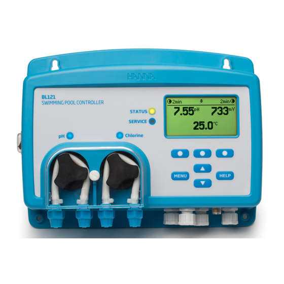
5.2. FUNCTIONAL & DISPLAY DESCRIPTION Front Panel The front panel includes a custom display and keypad with tactile feedback. Normally the first line displays measurement readings and the second line dispays temperature. Two LEDs indicate alarm status and service conditions. A red LED indicates fault condition. - Page 12 Rear Sub Panel Ethernet connector Note: The analog outputs – AO1, AO2, AO3 – are available only for BL121 & BL123. The Ethernet connector is available only for BL122 & BL123. Warning! Always disconnect the Pool Controller from power when making electrical connections. Do not access the larger rear panel.
-
Page 13: Wiring
5.3. WIRING 4 - 20 mA OUT – ANALOG OUTPUTS 4 - 20 mA OUT – (BL121 & BL123) 4 - 20 mA OUT – ETHERNET RJ-45 connector (BL122 & BL123) Ethernet connector DIGITAL INPUTS ALARM RELAY Line POWER INPUT Protective Earth Neutral Note: The analog outputs –... -
Page 14: Ethernet Cable Wiring (Bl122 & Bl123 Only)
5.4. ETHERNET CABLE WIRING (BL122 & BL123 ONLY) 1. Insert the ethernet cable through the knurled nut and the slotted rubber seal. 2. Insert the ethernet cable through the casing into the housing. 3. Insert the analog output connection cable through the same knurled nut and slotted rubber seal. Use a 6 conductor wire cable. -
Page 15: Installation
6. INSTALLATION There are two available configurations: • In-line, with the probe placed in saddle, mounted on pipe after the pool filter. • Flow cell, with the probe mounted in the flow cell, close to the controller. The water sample is directed to the flow cell via a small diameter sample line with appropriate connections (provided). - Page 16 In-Line Installation Overview & Components Table Below is an illustrated reference of a generic, in-line installation scheme with the relevant components. BL123 SWIMMING POOL CONTROLLER STATUS SERVICE Chlorine MENU HELP Position Component description Pool controller pH/ORP/temperature electrode Electrode fitting Flexible tubing for pump input Rigid tubing for pump output Aspiration filter Injector, ½”...
- Page 17 Flow Cell Installation Overview & Components Table Below is an illustrated reference of a generic, flow cell installation scheme with the relevant components. The maximum pressure of the flow cell system is 3 atm (44 psi). BL123 SWIMMING POOL CONTROLLER STATUS SERVICE Chlorine...
-
Page 18: Mounting Recommendations For Saddle
• With all the screws (7) in place, use a wrench to carefully tighten. • Place the O-ring (8) provided into the upper saddle. Probe Saddle (In-line Configuration) Thread Size Drill Size BL120-550 Ø 50 mm pipe 1 ¼”thread 29 mm - 32 mm / 1.14” - 1.26” BL120-563 Ø... -
Page 19: Connecting The Probe To The Pump Controller
6.4. CONNECTING THE PROBE TO THE PUMP CONTROLLER Ensure the probe is connected and calibrated before installation. 1. Remove protective cap and verify the O-ring is in place. 2. Insert the nut onto the probe. O-ring Nut adapter Protective cap 3. -
Page 20: Installing The Aspiration Filter
6.5. INSTALLING THE ASPIRATION FILTER The aspiration filter is used in the reagent tank to filter and prevent debris from entering the tubing. • Cut the required length of aspiration tubing (flexible) to reach between peristaltic pump inlet and aspiration filter. •... -
Page 21: Flow Cell Installation
6.7. FLOW CELL INSTALLATION In a flow cell configuration the water flows from the inlet valve to the flow cell and returns in the line via the outlet valve. PART A Preparing the inlet and outlet valve assemblies • Mount the saddle for flow cell inlet and outlet valve (follow mounting recommendations for saddle). -
Page 22: Cloud Connectivity (Bl122 & Bl123)
6.8. CLOUD CONNECTIVITY (BL122 & BL123) Hanna Cloud is a web based application that connects users to measurement devices such as the BL122 and BL123. Measurements and data storage are accessible from a PC, tablet or phone with an internet connection. Multiple registered devices may be connected. -
Page 23: Setup
• Acid (or base) pump control • Cl pump control • pH options (CAL, Setup, GLP) • ORP options (CAL, Setup, GLP) • Temperature options (Setup) • Hanna Cloud options (BL122 & BL123) • General options BL120 & BL121 OVERVIEW... - Page 24 BL122 & BL123 OVERVIEW HANNA CLOUD SETUP...
-
Page 25: General Setup Overview
7.2. GENERAL SETUP OVERVIEW General Options Parameter Range / Options Default settings Description Time Current set times Modifies current time hh:mm:ss 24h Time Format hh:mm:ss 24h Modifies current time format hh:mm:ss 12h Date Current set date Modifies current date yyyy-mm-dd, dd-mm-yyyy, Date Format mm-dd-yyyy, yyyy/mm/dd, yyyy-mm-dd... -
Page 26: Parameters Setup Overview
Parameter Range / Options Default settings Description Controller Password Enable Disabled Protects against unauthorized use Disable Controller ID 0 to 9999 / 1 1234 Identifies the controller Hold Input* Enable Disabled Enables or disables HOLD input for the recirculation ... - Page 27 Parameter Range / Options Default settings Description Enable Alarm High Disabled Enables / Disables the pH high alarm Disable Maximum pH value that triggers the low alarm if 0.0 to (pH High-0.1) pH continuous for more than 5 seconds** Alarm Low 6.0 pH Acid / 0.1 pH...
- Page 28 Parameter Range / Options Default settings Description Enable Alarm Low Disabled Enables / Disables the ORP low alarm Disable Enable Enables / Disables warnings and errors related to Warnings and Errors Disabled Disable ORP events Enable ...
-
Page 29: Hanna Cloud Setup (Bl122 & Bl123)
7.4. HANNA CLOUD SETUP (BL122 & BL123) Hanna Cloud Options These setting are required to permit cloud monitoring of your pool. IP addressing: An Internet Protocol address (IP address) is a numerical label assigned to each device connected to a network that uses the IP for communication. -
Page 30: Security Feature
Note: After five failed login attempts, the controller will require a master password. The master password can only be obtained from Hanna Instruments Service. To issue the master password, Hanna Service will request the user code displayed at the top of the screen. -
Page 31: Analog Outputs (Bl121 & Bl123)
7.6. ANALOG OUTPUTS (BL121 & BL123) The three 4-20 mA isolated current outputs are factory calibrated and can be configured through the Setup menu as pH / ORP or Temperature outputs. Each output can be disabled or configured to a parameter and can be connected to a chart recorder or data logger. The current signal is proportional to the assigned scale of the assigned parameter (e.g. -
Page 32: Operational Guide
8. OPERATIONAL GUIDE 8.1. CALIBRATION pH Calibration The pH electrode can be calibrated on the controller using an automatic, two-point calibration. The electrode should be calibrated: • Before in-line or flow cell installation • Whenever the pH electrode is replaced •... - Page 33 To delete a calibration, press CLR. Press YES to confirm or NO to exit and return to calibration screen. If the temperature sensor detects extreme values during calibration, or is broken, a blinking 25.0 °C is displayed, indicating controller compensation for this temperature variation. pH Calibration Error Messages Wrong Buffer Displayed when the difference between the pH reading and the value of the selected buffer is too high.
- Page 34 pH Process Calibration Prior to performing a process calibration, use a hand held meter and probe to determine the pH of the process. Write the value down. A process calibration allows the user to adjust the measured pH value so that it matches the value determined with the hand held meter and without removing the probe from the saddle.
- Page 35 ORP Calibration If both pH and ORP calibrations are required, calibrate the pH value first. A pH calibration can give inaccurate readings if the probe was used in ORP standard first. Preparation Pour small quantities of the ORP standard into clean beakers. If possible, use plastic beakers to minimize any EMC interferences. For accurate calibration and to minimize cross-contamination, use two beakers;...
-
Page 36: Measurement
8.2. MEASUREMENT Start the recirculation pump. Verify flow cell fills correctly (BL12X-20 only). After setting up the pump controller, probe and required accessories the controller is ready. Turn on the controller by switching ON/OFF button. After initialization has been completed, the controller displays the measurement screen. -
Page 37: Controller Functioning Modes (Overview)
In measurement mode the status bar displays the pumps status. BL120 & BL121 BL122 & BL123 Status Description The pumps are on Manual status. The pumps are on Manual status. The ORP is waiting for the pH to reach Set Point. - Page 38 Control Mode The Control Mode is the normal operational mode during which the controller: • Measures the HI1036-18XX probes signal, converts it to a measurement unit (pH temperature corrected), and displays the measurements on the display along with temperature. • Provides proportional feed with an adjustable band for acid and chlorine additions. •...
- Page 39 An overwiev of pH and ORP proportional control is presented in the graph below. THRESHOLD LEDs status STATUS SERVICE pH/Chlorine (controlling and pump off) (controlling and pump run) The alarm relay is energized (no alarms). Analog outputs follow the assigned parameters based on settings (BL121, BL123). Reagent pumps are disabled: •...
-
Page 40: Logging
8.4. LOGGING The controller logging system offers an automatic save mode for all parameters (pH, ORP, Temperature) and the following events: • High and Low alarms • Overtime errors • Hold Input • Remote Hold • Low tank level for acid or chlorine tanks •... - Page 41 Three screens display record details. • Press 1 / 3, 2 / 3 or 3 /3 to view more details. The Plot can be activated by pressing Plot. • If in the Log Recall summary screen the Option key is selected, the following screen is displayed. •...
-
Page 42: Event Management
9. EVENT MANAGEMENT BL12X controllers have an intuitive, user-friendly events management system that allows for a quick identification of event sources. The signalizing is done by using STATUS and SERVICE LEDs located on the front panel. The STATUS LED is a multicolor, red-yellow-green LED that indicates the controller status based on traffic light concept (... -
Page 43: Process Errors
Note: The logging period is higher than the measure period. Any alarm condition that occurred between logging moments is captured and logged even if the alarm conditions are no longer active on first log (event) after the alarm. Any alarm condition will inactivate the dosing pumps. During an alarm condition: •... -
Page 44: System Errors
Example: “Menu\pH options\Alarm Activates Relay ” for pH related errors • A beep is generated each time an error is triggered if Alarms and Errors Beep is enabled. • All errors are logged and visible in log RCL. • Any error condition will inactivate the dosing pumps. After an error has been signaled: •... - Page 45 The table describes LEDs status, dosing pumps, measurement and logging processes for different controller modes. LEDs Dosing pumps Modes Events With dosing delay at start-up Auto-Off Auto-Off No dosing Dosing Acid Auto-On Auto-Off Dosing Chlorine Auto-Off Auto-On High or Low alarms Auto-Wait Manual Off/On active...
-
Page 46: Maintenance
10. MAINTENANCE 10.1. ELECTRODE CONDITIONING & MAINTENANCE Preparation Remove the electrode protective cap. Do not be alarmed if any salt deposits are present. This is normal with electrodes and they will disappear when rinsed with water. During transport tiny bubbles of air may have formed inside the glass bulb. The electrode cannot function properly under these conditions. - Page 47 6. Fix the plastic holder in its place on the right and left side. 7. Place the plastic cover. Reattach the tubings to the pumps.
-
Page 48: Accessories
11. ACCESSORIES HI1036-1802 HI1036-1805 HI1036-1810 HI1036-1815 BL120-150 HI1036-1820 Fittings kit for Ø 50 mm pipe Industrial pH / ORP / Temperature / Matching Pin combined probes with 2 / 5 / 10 / 15 / 20 m cable BL120-163 BL120-175 Fittings kit for Ø... - Page 49 BL120-401 BL120-402 Flow cell valve Flow cell tubing (10 m) BL120-410 BL120-411 Flow cell for BL120, BL121, Flow cell panel spare part BL122, BL123 BL120-463 BL120-450 Flow cell kit for Ø 63 mm Flow cell kit for Ø 50 mm pipe...
- Page 50 Plastic nipple 2 x 1/2” with Metal nipple 12 x 1/2” O-rings (2 pcs.) BL120-603 BL120-604 Elbow for glass flow cell O-ring for glass flow cell BL120-901 BL120-902 Simulator for BL120, BL121, USB protective cap BL122, BL123 BL120-903 Cable gland protective kit (6 pcs.)
- Page 51 HI740036P Plastic beaker set, 100 mL (10 pcs.) ELECTRODE STORAGE SOLUTIONS HI70300L Storage solution, 500 mL BUFFER SOLUTIONS HI70004P pH 4.01 buffer sachets, 20 mL (25 pcs.) HI70007P pH 7.01 buffer sachets, 20 mL (25 pcs.) HI70010P pH 10.01 buffer sachets, 20 mL (25 pcs.) HI7004L pH 4.01 buffer solution, 500 mL HI7007L...
-
Page 52: Certification
(engraved on the bottom of the meter) and the nature of the problem. If the repair is not covered by the warranty, you will be notified of the charges incurred. If the instrument is to be returned to Hanna Instruments, first obtain a Returned Goods Authorization (RGA) number from the Technical Service department and then send it with shipping costs prepaid. - Page 53 Hanna Instruments reserves the right to modify the design, construction or appearance of its products without advance notice.
- Page 54 World Headquarters Hanna Instruments Inc. Highland Industrial Park 584 Park East Drive Woonsocket, RI 02895 USA www.hannainst.com MANBL12X Printed in ROMANIA...