Table of Contents
Advertisement
Quick Links
Advertisement
Table of Contents

Related Manuals for Hanna Instruments BL100


Summary of Contents for Hanna Instruments BL100
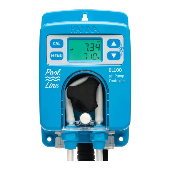
- Page 1 BL100 • BL101 pH & ORP Pump Controllers...
- Page 2 If you need additional technical information, do not hesitate to e‑mail us at tech@hannainst.com or view our contact list at www.hannainst.com. All rights are reserved. Reproduction in whole or in part is prohibited without the written consent of the copyright owner, Hanna Instruments Inc., Woonsocket, Rhode Island, 02895, USA.
-
Page 3: Table Of Contents
9.1. ALARMS ......................... 33 9.2. WARNINGS ......................34 9.3. SUMMARY OF GENERAL BEHAVIOR ................34 10. CALIBRATION ......................... 35 10.1. pH CALIBRATION (BL100 ONLY) ................35 10.2. PROCESS pH & ORP CALIBRATION ................37 10.3. CLEAR CALIBRATION ....................39 11. MEASUREMENT ......................40 12. -
Page 4: Preliminary Examination
1. PRELIMINARY EXAMINATION Remove the instrument and accessories from the packaging and examine it carefully. For further assistance, please contact your local Hanna Instruments Office or email us at tech@hannainst.com. Each instrument is delivered in a cardboard box and supplied with:... - Page 5 • Quick tubing fitting 1/2" to 12 mm (2 pcs.) • HI20083 ORP/temperature probe • Flow cell for BL100/BL101 • Flow cell valve (2 pcs.) • Mounting panel assembly for BL100/BL101 • PVC aspiration tubing (flexible) • Pool controller aspiration filter length: 5 m •...
-
Page 6: Safety Measures
2. SAFETY MEASURES • Do not use chlorine tablets, granular chlorine or other non-liquid chlorine applications. • Do not use the pump controller in a pool utilizing electrolytic chlorine generation (salt electrolysis). • Do not add stabilizer (e.g. cyanuric acid) to the swimming pool while using the pump controller. -
Page 7: Specifications
4. SPECIFICATIONS 4.1. BL100 pH CONTROLLER 0.00 to 14.00 pH * –5.0 to 105.0 °C (23.0 to 221.0 °F)* Range * The range may be limited by the probe’s limits. 0.01 pH Resolution 0.1 °C (0.1 °F) Accuracy ±0.10 pH @ 25 °C / 77 °F... -
Page 8: Bl101 Orp Controller
Power Supply 100 - 240 Vac, 50/60 Hz Power Consumption 15 VA Environment 0 to 50 °C (32 to 122 °F), max. 95% RH non-condensing Dimensions 90 x 142 x 80 mm (3.5 x 5.6 x 1.8") Weight 910 g (32 oz) Casing Wall mounted, built-in pump, IP65 rated 4.2. -
Page 9: Ph & Orp Probe Specifications
90 x 142 x 80 mm (3.5 x 5.6 x 1.8") Weight 910 g (32 oz) Casing Wall mounted, built-in pump, IP65 rated 4.3. pH & ORP PROBE SPECIFICATIONS Specifications HI10053 (BL100) HI20083 (BL101) Range 0 to 12 pH ±2000 mV Reference Double junction... -
Page 10: Description
5. DESCRIPTION 5.1. GENERAL DESCRIPTION & INTENDED USE BL100 & BL101 pump controllers are part of Hanna Instruments pool-line family and feature a single peristaltic dosing pump and a process electrode. BL100 accepts HI10053 pH probes. The BL101 accepts HI20083 ORP probes. - Page 11 Typically, 650-750 mV at 7.2 pH indicates proper water treatment. Based on individual requirements, users can define the ideal set point for pH (e.g. 7.2 pH for BL100) and ORP (e.g. 700 mV for BL101).
-
Page 12: Functional & Display Description
– When in menu mode, adjust settings. – When in menu mode, in Control screen, press the arrow keys together and a 10 seconds pump test will start. BL100 Liquid Crystal Display (LCD) 1. Stability indicator 5. Measurement unit 2. Mode tags 6. - Page 13 BL101 Front Panel MENU BL101 BL101 ORP Pump Contr oller 1. Keypad area 2. CAL key – Press calibration key to enter calibration mode. 3. MENU key – Press menu key to enter setup mode and move through the menu. –...
- Page 14 Rear Panel & Internal View Electrical hazard. Disconect power supply No user serviceable prior to cover removal. parts inside. Refer to quali ed personel. Warranty void if cover is removed. ALARM Surface. RELAY LEVEL SENSOR Electrical Rating: 100 - 240 VAC; 15 VA; 50 / 60 Hz Use a Phillips head screwdriver and remove the four screws, pull back the cover and remove it.
- Page 15 Alarm Relay, Power & Level Input No user serviceable parts inside. Warranty void if cover is removed. ALARM Surface. RELAY LEVEL SENSOR Normally Open ALARM RELAY OUTPUT Common SPDT 2.5 A / 230 Vac Normally Closed Pump controller not powered Alarm condition Working condition with no alarm Line –...
- Page 16 Tubing fittings Sensor input Cable gland for level sensor Drainage opening Cable gland for alarm cable Cable gland for power cable Enclosure cap Cabling safety measures. Qualified personnel should perform wiring only. • A disconnect switch must be installed to break all current carrying conductors. Turn off power before working on conductors.
-
Page 17: Installation
• The probes are easily installed using 1/2" NPT threads for in-line or flow cell installation. • Ensure all tubing, cables, saddles and fittings are properly connected. Note: BL100 BL101 pump controllers are shipped with two types of tubing, for both flow... - Page 18 Installation Schemes We are proposing a few typical installation schemes: in-line and flow cell. In-Line Installation, Overview & Parts Table A detailed representation of an in-line installation with relevant components is found below. The maximum pressure entering the flow cell system is 3 atm (44 psi). INJECTOR TANK FLOW...
- Page 19 Flow Cell Installation, Overview & Parts Table Below is an illustrated reference of a generic flow-cell installation scheme with the relevant components. The maximum pressure entering the flow cell system (P1) is 3 atm (44 psi) and decreases when it exits the flow-cell (P2).
- Page 20 Mounting Recommendations for Saddle • Select required drill size. See table for dimension details. Drill Pipe • Place the upper part of the saddle (3) on top of the pipe (5) with the seal (4) placed over the hole. • Take the lower part of the saddle (6), together with inserted nuts (7) and align it under the upper part.
- Page 21 Installing Aspiration Filter The aspiration filter is used in the reagent tank to filter and prevent debris from entering the tubing. • Cut required length of aspiration tubing (flexible) to reach between peristaltic pump inlet and aspiration filter. • Place the end of tubing on the filter. •...
- Page 22 Flow Cell Installation In a flow cell configuration, the water flows from the inlet valve to the flow cell and returns in the line via the outlet valve. To prepare the inlet and outlet valve assemblies, as illustrated in the drawing: •...
- Page 23 Connecting the Probe to the Pump Controller (Flow Cell Configuration) • Remove the protective cap and verify the O-ring (2) is in place. Note: The probe should be connected to the controller and calibrated before installation. • To avoid twisting the cable, unplug probe from socket temporarily while installing in flow cell. •...
-
Page 24: Setup
• Long press MENU key to exit. • Press arrow keys to change the values. • Short press MENU key to automatically save modified values. Table below presents an overview of BL100 menu with ranges and factory set defaults. Parameter Range / Option... - Page 25 Table below presents an overview of BL101 menu with ranges and factory set defaults. Parameter Range / Option Default Settings (Scrolled message) Control Auto or oFF Auto Control type on/oFF or Proportional on/oFF Control mode Hi or Lo Set point 200 to 900 mV 700 mV Hysteresis (on/oFF only)
- Page 26 Control Option: Auto or Off (oFF) to enable or disable the control With disabled option oFF, the control is off. Press one of the arrow keys for the controller settings to change from Auto to oFF and vice versa. To run a ten-seconds pump test, long press the arrow keys together until the pump starts to run. ”CONTROL”...
- Page 27 With a Hi control mode, the measurement approaches the set point from a lower measurement value. With a Lo control mode, the measurement approaches the set point from a higher measurement value than the set point. Option: user selectable Press the arrow keys to assign the set point value. ”SET POINT”...
- Page 28 Startup Delay (Automatic Control Only) Option: user selectable (0 to 600s) Startup delay represents the delay to start dosing at power-on. Press the arrow keys to change the time values. ”STARTUP DELAY SEC” message is scrolled on the bottom of the LCD screen. Note: To enter Startup Delay screen, pump control mode must be set as Auto.
- Page 29 Level Alarm Option: Enabled (En) or disabled (diS) Press the arrow keys to switch between the options. ”LEVEL ALARM” message is scrolled on the bottom of the LCD screen. Note: Option can only be used with properly wired level sensor. High Alarm Option: Enabled (En) or disabled (diS) Press the arrow keys to switch between the options.
- Page 30 Low Alarm Value Option: user selectable The range is influenced by the high-alarm value set (e.g. if high-alarm value is set as 8 pH, low-alarm value can be set from 0.00 pH and incremented up to 7.90 pH). ”LOW ALARM VALUE” message is scrolled on the bottom of the LCD screen. Note: The user can set the low-alarm value with low-alarm option enabled only.
-
Page 31: Priming The Pump
8. PRIMING THE PUMP Pump control can be enabled (automatic control) or disabled (off; manual control). See SETUP section for further details on how to enable or disable pump control. LCD backlight color indicates the pump control status: • green - automatic control or in View menu mode •... -
Page 32: Priming The Pump
On/O Control Hi control mode on the BL100 Lo control mode on the BL100 Pump running continuously Pump running continuously Pump status Pump status at the con gured ow rate at the con gured ow rate RUNNING RUNNING Hysteresis Hysteresis... -
Page 33: Events Management
9. EVENTS MANAGEMENT 9.1. ALARMS Alarms can be independently enabled or disabled in SETUP. Any event that activates the alarm turns automatic control Off, the alarm relay is deactivated and the LCD backlight is blinking red. The table below illustrates the conditions that will activate the alarm and deactivate the control pump. Alarm Description Alarm condition... -
Page 34: Warnings
9.2. WARNINGS Two types of warnings can be independently enabled or disabled in SETUP. If any of the warnings is active, the LCD backlight turns light green. Screenshot for Warnings Description Solution warning solution Press the up / down arrows at same time to restart pump. -
Page 35: Calibration
10. CALIBRATION 10.1. pH CALIBRATION (BL100 ONLY) The BL100 provides a digital calibration at the push of a button. Calibrate the probe frequently for improved accuracy. Also: • before in-line or flow cell installation • whenever the probe is replaced •... - Page 36 • If the buffer is not recognized (either because the pH electrode has not been placed in solution or the reading is outside accepted range), ”---- WRONG” message is displayed along with CAL tag blinking. • After pH 4.01 or 10.01 buffer is accepted, the ”SAVE” message is displayed and the controller returns to measurement mode.
-
Page 37: Process Ph & Orp Calibration
• The ”CAL” tag will be displayed in measurement mode after the calibration. • If the buffer is not recognized, ”---- WRONG” message is displayed. It is recommended to change the solution and / or clean the electrode. • Press CAL key to exit calibration. Note: If high accuracy is required, a two-point calibration is recommended. - Page 38 • Press CAL key to confirm the value (the ”SAVE” message appears for a few seconds). • Press MENU key to exit without saving and return to measurement mode (the ”ESC” message is displayed for a few seconds). Process ORP Calibration (BL101 only) ORP calibration is a single point process calibration.
-
Page 39: Clear Calibration
10.3. CLEAR CALIBRATION • Press CAL key and the controller enters calibration mode. • Long press MENU key and the ”CLEAR” message is displayed. • No “CAL” tag in measurement mode, indicates the probe is no longer calibrated. LONG LONG... -
Page 40: Measurement
• If control mode is enabled (Auto), the pump tag will be displayed. If control is disabled (oFF), the pump tag will be crossed out. BL100, control enabled BL101, control disabled First LCD line displays measured pH / ORP value, the second LCD line displays the temperature. -
Page 41: Error Messages
Wrong probe is connected. Unplug the controller and connect the correct probe. Broken temperature sensor. Replace the probe. Temperature is out of range (BL100). Measured value is out of range. pH (BL100) or ORP (BL101). Stepper motor error: over temperature or overcurrent is detected. -
Page 42: Maintenance
13. MAINTENANCE 13.1. ELECTRODE CONDITIONING & MAINTENANCE Preparation • Remove the electrode protective cap. Do not be alarmed if any salt deposits are present, this is normal. Rinse the probe with water. • Shake the electrode down as you would do with a clinical thermometer to eliminate any air bubbles inside the glass bulb (pH electrode only). - Page 43 (4B), until the tubing is removed (4C). 5. Grease the new peristaltic pump tubing with silicone oil supplied in the peristaltic pump tubing kit (BL100-300). 6. Place the greased new peristaltic tube on the left side of the pump (6A) and rotate the pump rotor manually to the right (6B) until the tubing is on the pump.
-
Page 44: Accessories
14. ACCESSORIES HI10053 pH/temp. HI20083 ORP/temp. probe with 2 m cable, probe with 2 m cable, DIN Quick connect DIN Quick connect BL100-302 BL120-410 Pump cover Flow cell for with screw BL100/BL101 BL100-400 Probe adapter kit BL100-421 (contains adapter, Flow cell panel fixing nut, O-ring) ×2... - Page 45 Injector saddle for Injector saddle for Ø 50 mm pipe, Ø 63 mm pipe, 1/2" NPT thread 1/2" NPT thread BL120-275 BL100-300 Injector saddle for Peristaltic pump Ø 75 mm pipe, tubing kit (2 pcs.) 1/2" NPT thread BL120-301 BL120-401...
-
Page 46: Certification
If service is required, contact your local Hanna Instruments Office. If under warranty, report the model number, date of purchase, serial number (engraved on the bottom of the meter) and the nature of the problem. - Page 47 Hanna Instruments reserves the right to modify the design, construction or appearance of its products without advance notice.
- Page 48 World Headquarters Hanna Instruments Inc. Highland Industrial Park 584 Park East Drive Woonsocket, RI 02895 USA www.hannainst.com MANBL10X Printed in ROMANIA...