
Related Manuals for Agilent Technologies Intuvo 9000


Summary of Contents for Agilent Technologies Intuvo 9000
- Page 1 Agilent Intuvo 9000 Gas Chromatograph Installation and First Startup Agilent Technologies...
- Page 2 C A U T I O N without prior agreement and written by applicable law, Agilent disclaims all consent from Agilent Technologies, Inc. as warranties, either express or implied, with A CAUTION notice denotes a hazard. It governed by United States and...
-
Page 3: Table Of Contents
Power consumption Power cords available Grounding If purchased, install the ALS tray support brackets. Intuvo 9000 7693A Tray Support Assembly kit contents Install the pivot block and stop bracket Connect the power cord and LAN cable. Turn on the GC. - Page 4 Condition the column and bake out the detector. Transfer the checkout sample to a screw-top sample vial. Enter the checkout method. Run one injection. Evaluate Results. Prepare for the next analysis. If appropriate, update firmware. GC firmware Agilent Intuvo 9000 GC Installation...
- Page 5 Remote start/stop cable, general use, 35900-60670 Agilent APG remote start/stop cable, 03396-61010 Agilent APG remote start/stop cable, G1530-60930 Agilent remote start/stop Y-cable, G1530-61200 BCD cable, G1530-60590 BCD cable, G1530-61100 External event cable, G1530-60590 External valve cable, G1580-60710 Agilent Intuvo 9000 GC Installation...
- Page 6 Agilent Intuvo 9000 GC Installation...
-
Page 7: Installing The Gc
Installation and First Startup Installing the GC This section contains installation procedures for the Agilent Intuvo 9000 GC. Some of the steps in this procedure are optional based on your installed components, such as plumbing cryogenic cooling or valve actuator air. -
Page 8: Overview Of Installation
Refer to the Agilent Intuvo 9000 GC, GC/MS, and ALS Site Preparation Guide. If Agilent is delivering installation and familiarization services, users of the instrument should be present throughout these services;... -
Page 9: Tools And Additional Parts Required
LAN (not included in Agilent installation services). The Agilent Intuvo 9000 GC, GC/MS, and ALS Site Preparation Guide contains a listing of Agilent installation kits and a description of parts included with each. These kits contain filters, fittings, tubing, tools (wrenches, tubing cutter, drivers, and so on), and other required parts for installing a GC.) -
Page 10: System Installation
LAN cable Intuvo Torque Driver handle and extension Torx keys, T10 and T20 Gas line ID labels Agilent Intuvo 9000 Gas Chromatograph Safety Information manual MSD Cover insert assembly Intuvo inlet chip, G4581-60031 Bus front door assembly, G4581-60207 Compression bolts (2), G4581-60260... -
Page 11: The Intuvo 9000 Gc
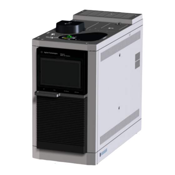
Inlet Cooling intakes Touch screen display Front door handle Power on and status Cooling intake indicators Figure 1 Front of the Intuvo 9000 GC Inlet gas connection Detector gas connections Exhaust vents Signal and communications connections Power switch Power receptacle... -
Page 12: Unpacking
Check the items received against the packing lists. If there are discrepancies, notify your local Agilent sales office immediately. Keep the shipping containers until you have checked their contents for completeness and verified instrument performance. Agilent Intuvo 9000 GC Installation... -
Page 13: Place The Gc On The Bench
Place the GC on the bench top. Make sure gas and power supplies are accessible. Place related equipment near the GC. If space is limited behind the GC, attach the optional oven exhaust deflector to the back of the GC as shown below. Agilent Intuvo 9000 GC Installation... - Page 14 7.6 cm to the depth of the GC, but this additional depth does not increase the depth required for proper ventilation. You will only need 20.3 cm (8 in) from the GC back panel. Agilent Intuvo 9000 GC Installation...
-
Page 15: Verify Line Voltage And Power Cord
Power line conditioners should not be used with the GC. Power cords available Table 2 lists the power cords available for the GC. If your power cord is incorrect, order the cord appropriate for the country. Agilent Intuvo 9000 GC Installation... - Page 16 Australia AS 3112 China GB 1002 Europe, Korea 220 / 230 / CEE 7/7 Type F Switzerland SEC Type 12 India, South Africa 220 / 230 / IEC 83-B1 Israel Israeli SI32 Japan NEMA 5-15P Agilent Intuvo 9000 GC Installation...
- Page 17 NEMA L6-20P United Kingdom, Hong BS89/13 Kong, Singapore, Malaysia United States NEMA 5-15P Europe 220 / 230 / CEE 7/7 Type F Denmark / Greenland SR 107-2-D1 DK2-5A Argentina Type I Chile CEI 23-16 Type L Agilent Intuvo 9000 GC Installation...
-
Page 18: Grounding
Make sure the GC is connected to a dedicated receptacle (outlet). Appliance Coupler (mains input power cord) is the power WA RNING disconnect device. Do not position the instrument such that access to the coupler is impaired. Agilent Intuvo 9000 GC Installation... -
Page 19: If Purchased, Install The Als Tray Support Brackets
Installing the GC If purchased, install the ALS tray support brackets. If installing a 7693A ALS tray with this Intuvo 9000 GC, install the pivot bracket, support bracket, and support truss now. (Refer to the Intuvo 9000 7693A Tray Support Assembly, accessory G7390A). - Page 20 Installing the GC Install pivot block Remove the GC top cover. Remove the GC right side panel. Remove left side panel. Agilent Intuvo 9000 GC Installation...
- Page 21 (0515-2113), then attach three screws (0515-2113) to the bottom three holes of the pivot block. If not using a D2 or MSD, remove the two captive screws in the left-side panel. Install the left side panel onto the GC Agilent Intuvo 9000 GC Installation...
- Page 22 If not using a D2 or MSD, install the MSD cover insert, then attach the support truss (G4580-60517) to left side of GC. If using a D2 configuration or MSD, you will not have a support truss. Skip this step. Agilent Intuvo 9000 GC Installation...
- Page 23 Installing the GC Match the slots on the left side of the GC. Secure the support truss with two thumbscrews (0515-6137). Agilent Intuvo 9000 GC Installation...
- Page 24 Installing the GC Install the stop bracket on the right side of the GC Install the stop bracket with four screws (0515-2113). The label “ONE DEGREE TILT” should face outward. “ONE DEGREE TILT” Install the right-side cover. Agilent Intuvo 9000 GC Installation...
- Page 25 Installing the GC Reinstall the GC covers. Agilent Intuvo 9000 GC Installation...
-
Page 26: Connect The Power Cord And Lan Cable
Installing the GC Connect the power cord and LAN cable. Agilent Intuvo 9000 GC Installation... -
Page 27: Turn On The Gc
Installing the GC Turn on the GC. Agilent Intuvo 9000 GC Installation... -
Page 28: View The Feature Tour
To skip displaying the Feature Tour each time the GC is turned on, select Don’t show again. The Feature Tour can be viewed from the help at any time. Touch ? > Help and Information > Familiarization > Feature Tour. Agilent Intuvo 9000 GC Installation... - Page 29 Installing the GC Agilent Intuvo 9000 GC Installation...
-
Page 30: View The System Setup Wizard
After exiting the system setup wizard, you can re-launch it at any time. On the GC touch screen, navigate to Settings > System Setup and touch Run System Setup. Agilent Intuvo 9000 GC Installation... -
Page 31: Set The System Time Zone, Date, Time, And Pressure Units
(such as maintenance tasks and errors). The GC time also controls resource conservation for connected samplers. Touch Settings > Configuration > Misc and select the desired pressure units to use in methods. Agilent Intuvo 9000 GC Installation... -
Page 32: Configure The Gc Ip Address
Configure the GC IP address. Touch Settings > System Settings > Network. Enter the GC Host Name or IP address, Gateway, and Net Mask (subnet mask). For an isolated LAN installation, see Table 3 for typical IP Agilent Intuvo 9000 GC Installation... - Page 33 Remote, 9-pin male/6-pin connector G1530-60930 G1289B/G1290B Headspace Sampler Remote, 9-pin male/6-pin connector G1530-60930 PAL automatic sampler Cable, 4 conductor, remote start G6500-82013 Mass Spectrometers and MS systems Mass Selective Detector Remote, 2-m, 9-pin male/9-pin male G1530-60930 Integrators Agilent Intuvo 9000 GC Installation...
-
Page 34: Configure The 5977B Ms
Scroll to the MSD Network Configuration settings to enter the MSD IP address and related settings. The MSD IP address entered here must exactly match the IP address entered in the data system. The GC already knows most details about the MSD, however, Agilent Intuvo 9000 GC Installation... -
Page 35: Configure Another Ms Type
Touch Settings > Configuration > Detectors, then select the tab for the MSD. The MSD IP address entered here must exactly match the IP address entered in the data system and at the MSD keyboard. Agilent Intuvo 9000 GC Installation... -
Page 36: Prepare The Gc
On the top of the GC, remove any tape used to secure covers, and remove any protective caps placed on detector exhaust port. Back panel caps Tape and detector exhaust cap Door clamp Cryo coolant fitting cap (if present) Agilent Intuvo 9000 GC Installation... - Page 37 MSD frame cover after installing the tray mounting hardware. • If installing an MSD or D2 assembly, skip this step. Assemble the Intuvo Torque Driver and attach it to the GC front door. The calibrated torque driver handle (8710-2790) Agilent Intuvo 9000 GC Installation...
- Page 38 (G4581-20522) can be found in the 9000 GC System Ship kit, G3950-68000. Intuvo Torque Driver Remove protective packaging. 7 mm Open the oven door. Loosen any ties that secure the oven packing in place, and remove the oven packing. Agilent Intuvo 9000 GC Installation...
- Page 39 Install the bus door, G4581-60207. The door rests on two hinge pins in the GC. Bus door Front view If you are not installing a tray, MSD, or D2, install the MSD cover insert assembly. Agilent Intuvo 9000 GC Installation...
-
Page 40: Configure Gases And Detector-Specific Settings
Touch Settings > Configuration > Inlet to set the inlet carrier gas type and, for a multimode inlet, to select the cryo gas type. Touch Settings > Configuration > Detectors to set the detector gas type or types. Agilent Intuvo 9000 GC Installation... -
Page 41: Connect To The Gc And View The Complete Installation Guide
GC connect to the same LAN. No Internet connection is required. (A direct connection using a LAN cable between the GC and a PC will also work.) http:// 10.1.1.101 /install Intuvo 9000 GC http://10.1.1.101/install Agilent Intuvo 9000 GC Installation... -
Page 42: Prepare Gas Supplies
Install the gas regulators Select the appropriate CGA regulator for each gas type. (In other countries, refer to local standards. See the Agilent Intuvo 9000 GC, GC/MS, and ALS Site Preparation Guide for requirements.) Table 5 Gas regulators, 1/8-inch, U.S. only... - Page 43 Install the regulator onto the compressed gas cylinder main fitting. • Check the thread type. Some regulators use left-hand thread fittings. For left-handed threads, the nut will have a groove in it. Groove indicates left-hand thread Agilent Intuvo 9000 GC Installation...
- Page 44 In the example shown below, which uses an optional shutoff valve, open the shutoff valve and leave open during purging. Secondary gauge Primary gauge Shutoff valve (optional) Main tank valve Regulator knob Swagelok adapter Agilent Intuvo 9000 GC Installation...
-
Page 45: Connect Tubing To Gas Supplies And Purge
Typical tubing cutter Connect the tubing to the gas source with a Swagelok fitting. Appendix A, “Making Swagelok Connections. Purge the supply lines for a few minutes before connecting them to the GC flow modules. Agilent Intuvo 9000 GC Installation... -
Page 46: Install Filters And Traps, Then Purge
Connect the traps and tubing. On/Off valves are not essential, but are very useful when a tank or trap must be changed. (If purchasing Agilent compliance services, install an on/off valve for the inlet gas supply.) Agilent Intuvo 9000 GC Installation... -
Page 47: Connect Gases To The Gc
Tee fitting that includes shutoff valves for performing leak tests. 60 mm = ~ 2 1/4 inches 33 mm = ~ 1 5/16 inches 33 mm = ~ 1 5/16 inches Figure 7 Example Tee with shutoff valves Agilent Intuvo 9000 GC Installation... - Page 48 When two detectors use the same gases, we recommend using a Tee fitting. Shutoff valves are not required. TCD connections The carrier gas and reference gas must come from the same source. Use a Tee fitting. Agilent Intuvo 9000 GC Installation...
-
Page 49: Leak Test All Connections And Set Source Pressures
Swagelok fittings and copper tubing are more than adequate for the highest pressures used in gas chromatography. We recommend a maximum continuous operating pressure of 1170 kPa (170 psi) to avoid excessive wear and leaks. Agilent Intuvo 9000 GC Installation... - Page 50 Air for FID, FPD Detectors 550 kPa (80 psi) Hydrogen Detectors 410 kPa (60 psi) Makeup gas Detectors 410 kPa (60 psi) TCD Reference 410 kPa (60 psi) Air for valve actuators Valves 345 kPa (50 psi) Agilent Intuvo 9000 GC Installation...
-
Page 51: Vent Hazardous Gases To A Fume Hood
FID vent chimney. If FID combustion will create corrosive gases, such as the HCl produced during the combustion of methylene chloride solvent, install the FID vent chimney. Connect the exhaust to a fume hood as needed. Agilent Intuvo 9000 GC Installation... - Page 52 Installing the GC Detector cover Vent chimney Screw O-Ring Agilent Intuvo 9000 GC Installation...
-
Page 53: Connect Cryogenic Cooling (If Present)
Consult your local supplier for recommended safety precautions and delivery system design. See the Intuvo 9000 GC, GC/MS, and ALS Site Preparation Guide for important requirements for tubing. Do not use padded tanks for CO supplies. -
Page 54: Connecting Liquid Nitrogen
Liquid nitrogen can present an asphyxiation hazard if vaporizing nitrogen displaces oxygen in the air. Consult local suppliers for safety precautions and design information. See the Intuvo 9000 GC, GC/MS, and ALS Site Preparation Guide for important requirements for tubing. Agilent Intuvo 9000 GC Installation... - Page 55 Connect the supply tubing to the liquid N2 tank outlet with the fitting recommended by the supplier. Use a Swagelok fitting to connect the supply tubing to the cryogenic valve inlet. Agilent Intuvo 9000 GC Installation...
-
Page 56: Connecting Air To The Multimode Inlet
Installation of a compressed air line to the inlet cryo coolant valve requires the hardware (and appropriate fittings) noted below: • Use 1/4-inch copper or stainless steel tubing for supply tubing to the N2 valve. Agilent Intuvo 9000 GC Installation... - Page 57 GC. Prepare enough tubing to reach from the supply to this outlet. Connect the supply tubing to the air supply outlet with the fitting recommended by the supplier. Use a Swagelok fitting to connect the supply tubing to the cryogenic valve input fitting. Agilent Intuvo 9000 GC Installation...
-
Page 58: Connect Valve Actuator Air (If Present)
Turn off the air supply at the source. If needed, shorten the supplied plastic tubing using a sharp knife. Connect the tubing to the air source using a 1/4-inch Swagelok nut and ferrules. Agilent Intuvo 9000 GC Installation... -
Page 59: Connect The External Cables
If using an ALS, connect it to the GC using the following connectors: ALS 1 Optional. An injector or 150-position sample tray. ALS 2 Optional. An injector or 150-position sample tray. The SIG (analog output) connectors Optional. Use SIG1 and SIG2 for analog output signals. Agilent Intuvo 9000 GC Installation... - Page 60 C A U T I O N non-BCD cable into the BCD connector can damage the GC. LAN connector Standard Local Area Network (LAN) connector, for communication with data systems and other devices via TCP/IP. Agilent Intuvo 9000 GC Installation...
-
Page 61: Connecting Cables
• G1580-60730, Pulser Module Power Supply Cable • G1580-61100, BCD Cable Assembly For other cables, apply an Event or BCD label to the cable: • G1580-87100, Caution label, BCD cable, purple • G1580-87200, Caution label, Events cable, green G1580-87100 G1580-87200 Agilent Intuvo 9000 GC Installation... -
Page 62: Gc / Ms / Agilent Data System / Als
8121-0940, Cable, LAN, 25 foot The communications cable used to connect a 5977B to the 9000 GC is included with the MS. Additional cabling configurations For additional cabling configurations, see Appendix B, “Cabling Diagrams and Remote Start/Stop." Agilent Intuvo 9000 GC Installation... -
Page 63: Install Als, If Available
Install tray bracket onto the tray (7693A only) If a tray is not available, skip this section. Gently park the gantry. If new, remove all of the shipping clamps from the tray. (Refer to the ALS documentation.) Agilent Intuvo 9000 GC Installation... - Page 64 Installing the GC Place the bracket on the tray. Tighten the captive screws. Figure 8 Assembling the tray bracket to the tray Figure 9 Bracket and tray (assembled) Agilent Intuvo 9000 GC Installation...
-
Page 65: Install The Tray On The Gc (7693A Only)
If a tray is not available, skip this section. Place tray on the GC, inserting the tray bracket into the stop bracket. Lock the tray in place. Connect the tray to the GC (the ALS 2 connector). Agilent Intuvo 9000 GC Installation... -
Page 66: Install The Injector
Installing the GC Install the injector To install an injector: Install mounting post. Mount the injector. Connect the cable to the GC (ALS 1 connector). Agilent Intuvo 9000 GC Installation... -
Page 67: Configure The Als
Installing the GC Configure the ALS Configure the injector and tray (if installed). Select the syringe size and wash mode as applicable. (The syringe supplied by Agilent with an injector is typically 10 μL.) Agilent Intuvo 9000 GC Installation... -
Page 68: Calibrate The Tray, If Installed
Installing the GC Calibrate the tray, if installed If installed, calibrate the tray before first use. Agilent Intuvo 9000 GC Installation... -
Page 69: Prepare The Als For Checkout
Prepare fresh solvent solutions as needed for the checkout sample for your detector type. Place the solvent vials into the injector turret. For details on the solvent needed, see the Agilent Intuvo 9000 GC Operation Manual. Agilent Intuvo 9000 GC Installation... -
Page 70: Install The Intuvo Chips And Column
Inlet sealing screw Inlet chip Smart ID key connector Clips Detector chip Smart ID key Gasket connector Inlet chip Detector chip Gasket Compression bolt Figure 10 Intuvo GC bus components (split/splitless inlet with D1 chip shown) Agilent Intuvo 9000 GC Installation... -
Page 71: Remove The Packing Materials
Open the oven door. Remove the column plug and gasket. Remove the compression bolts using the torque driver. Remove the plug and discard. Remove and discard the gasket. Gasket Plug Compression bolts Figure 11 Remove the column plug Agilent Intuvo 9000 GC Installation... - Page 72 Loosen inlet sealing screw Guard chip heater assembly (shown lowered) Split/Splitless inlet Remove plug Use two wrenches to loosen inlet sealing screw Guard chip heater assembly (shown lowered) Multimode inlet Figure 12 Remove the inlet base plug Agilent Intuvo 9000 GC Installation...
-
Page 73: Install The Intuvo Inlet Chip And Guard Chip
Slide open the Guard chip cover to expose the Guard chip compression bolt. Using the Intuvo torque driver, loosen the Guard chip compression bolt until there is a clear space between the bottom of the bolt and the little bus. (Access the Guard Agilent Intuvo 9000 GC Installation... - Page 74 C A U T I O N little bus. Seat the chip's column connector into the column fitting. Check your work. Both click and run connectors should be centered in their fittings, the chip's connector in the Agilent Intuvo 9000 GC Installation...
- Page 75 Inlet chip routes under wire from detector chip Figure 15 Place the inlet chip – check your work Insert the inlet chip Smart ID key into the lower socket to the right of the bus. See Figure Agilent Intuvo 9000 GC Installation...
- Page 76 Rotate the body of the Guard chip into the GC, lifting the Guard chip right end over the little bus and into the pocket. The little bus can move a bit if needed to help seat the Guard chip. Agilent Intuvo 9000 GC Installation...
- Page 77 Guard chip compression bolt. Gently raise the Guard chip heater. Finger-tighten the inlet sealing screw. Tighten the inlet sealing screw. For MMI, use two wrenches. (See the figure below.) Agilent Intuvo 9000 GC Installation...
-
Page 78: Install A New Column Gasket
(Note that the gasket is double-sided.) Locate the hole in the gasket, align it over the pin on the bus fitting, and press the gasket body flat against the bus so the pin fits through the alignment hole. Agilent Intuvo 9000 GC Installation... - Page 79 Gasket lobes centered in pocket Check that the gasket’s round lobes remain flat, with no wrinkles, and are centered on top of the mating flow chip sealing surfaces. See the figure below. Agilent Intuvo 9000 GC Installation...
-
Page 80: Install The Checkout Column
The column connectors should rest flat on top of both gasket lobes, so that the flow chip, gasket, and column connector lobes all align concentrically. See the figures below. Agilent Intuvo 9000 GC Installation... - Page 81 Installing the GC Check column placement. The center hub of the column connector heater should fit in the slot in the column neck as shown below. Install the compression bolts finger-tight. Agilent Intuvo 9000 GC Installation...
- Page 82 1 thread, the column may not be properly seated. Remove the bolts and repeat step Check column placement and tighten the compression bolts. Tighten the compression bolts until you hear one click (typically less than a 1/4-turn). Agilent Intuvo 9000 GC Installation...
- Page 83 Insert the column’s Intuvo Smart ID Key into the lower USB connection along the right side of the oven. Close the oven door. Install the bus door. Install the bus door. Place the torque wrench back in the front door of the instrument. Agilent Intuvo 9000 GC Installation...
- Page 84 Installing the GC Close the GC front door. Agilent Intuvo 9000 GC Installation...
-
Page 85: Condition The Column And Bake Out The Detector
Light the flame, if appropriate. Condition for the time given in the column’s instructions. Cool the oven. Leave the carrier gas on. If using a flammable carrier gas (hydrogen), continue to vent the exhausts to a fume hood. Agilent Intuvo 9000 GC Installation... -
Page 86: Transfer The Checkout Sample To A Screw-Top Sample Vial
Use a pipette to transfer the sample to a 2-mL screw-top vial. (If using an ALS, use a vial suitable for the ALS turret or tray.) Agilent Intuvo 9000 GC Installation... -
Page 87: Enter The Checkout Method
Enter the parameters for the checkout procedure. • If using an Agilent data system, use it to create a checkout method. • If not using a data system, enter the setpoints using the touch screen. Agilent Intuvo 9000 GC Installation... -
Page 88: Run One Injection
• For an ALS injection, press on the GC or start the run from the data system, as appropriate. • For a manual injection, inject the sample and press Agilent Intuvo 9000 GC Installation... -
Page 89: Evaluate Results
Installing the GC Evaluate Results. Compare the chromatogram you generated with the one in the checkout procedure. There should be a close resemblance. Agilent Intuvo 9000 GC Installation... -
Page 90: Prepare For The Next Analysis
If installing a second column, remove the bus door air shield from the bottom of the bus door so the door will accommodate the second column. (See the Maintaining Your GC manual.) Agilent Intuvo 9000 GC Installation... -
Page 91: If Appropriate, Update Firmware
Click the GC Firmware Update Tool icon. (If your browser does not start the installer, browse to the DVD and run file <DVD drive letter>:\tools\GCFWUpdate\setup.exe.) Read the instructions, then install the utility as described. Check the GC firmware version. Touch Settings > About. Agilent Intuvo 9000 GC Installation... - Page 92 If the new firmware is not compatible or acceptable for any reason, skip to the next section. If available, install any available firmware updates. Agilent Intuvo 9000 GC Installation...
- Page 93 Agilent Intuvo 9000 Gas Chromatograph Installation and First Startup Making Swagelok Connections Making Swagelok Connections Using a Swagelok Tee The gas supply tubing is attached with Swagelok fittings. If you are not familiar with Swagelok connections, review the following procedures.
-
Page 94: Making Swagelok Connections
Do not use an inlet or detector fitting. Strong forces are required to properly set the ferrules, and damage to an inlet or Do not detector fitting is very costly to repair. Agilent Intuvo 9000 GC Installation... - Page 95 Push the tube fully into the plug, then withdraw it approximately 1 to 2 mm (see Figure 19). Front ferrule Insert tubing fully Back ferrule Withdraw tubing 1-2 mm Tighten nut Figure 19 Insert the tubing Finger-tighten the nut. Agilent Intuvo 9000 GC Installation...
- Page 96 Both correctly- and incorrectly-swaged connections are shown in Figure 22. Note that the end of the tubing in a correctly-swaged fitting is not crushed and does not interfere with the action of the ferrules. Figure 22 Completed fitting Agilent Intuvo 9000 GC Installation...
-
Page 97: Using A Swagelok Tee
• 1/8-inch Swagelok cap (optional) Procedure: Cut the tubing where you want to install the Tee. Connect the tubing and Tee with a Swagelok fitting. See Figure Tee fitting Nut and ferrules Figure 23 Swagelok tee Agilent Intuvo 9000 GC Installation... - Page 98 Making Swagelok Connections Measure the distance from the Tee to the instrument fittings. Attach copper tubing to the open Tee ends with Swagelok fittings. Agilent Intuvo 9000 GC Installation...
- Page 99 Agilent Intuvo 9000 Gas Chromatograph Installation and First Startup Cabling Diagrams and Remote Start/Stop Using the Remote Start/Stop Cable Multi-instrument Cabling Examples Cable Diagrams This section lists cabling requirements and connection diagrams that apply to less common or specialized GC installations.
-
Page 100: B Cabling Diagrams And Remote Start/Stop
2.2 V. Higher leakage current may cause the state to be interpreted as a low. Over-voltage protection: APG Remote connections are clamped by a Zener diode to 5.6 V. Exceeding this voltage will damage the circuit (GC logic board). Agilent Intuvo 9000 GC Installation... - Page 101 Gas Saver. This function is not needed by Agilent autosampler systems. Ready (High True) If the Ready line is high (> 2.2 VDC) then the system is ready for next analysis. Receiver is any sequence controller. Agilent Intuvo 9000 GC Installation...
- Page 102 Receiver is any module performing runtime-controlled activities. Normally this line is not connected, if the GC oven program is used to control the method Stop time. APG Remote timing diagram Prepare H Start Stop Ready Agilent Intuvo 9000 GC Installation...
-
Page 103: Multi-Instrument Cabling Examples
24 V Out 2 Start Ground Shut down Green White Ground Reserved Brown Orange Contact 1 Power on Blue Green Contact 1 Ready Orange Brown Contact 2 Stop Yellow Blue Contact 2 Start Request Violet Agilent Intuvo 9000 GC Installation... -
Page 104: Using A Y-Cable In A Setup (Gc/Msd/Data System/Headspace Sampler)
2. APG Remote Y-Cable, G1530-61200 Number Part number and description G1530-61200, 2-m Y-cable, remote start/stop 8121-0940, Cable, LAN, 25 foot GC / External Events (unspecified, non-Agilent instrument) 1. External event cable, 8 pin/spade lugs, G1530-60590 GC/ALS Agilent Intuvo 9000 GC Installation... - Page 105 Ground Ground White Relay contact closures (normally open) Contact closure 1 48V AC/DC, 250 mA Orange Contact closure 1 Green Contact closure 2 48 V AC/DC, 250 mA Brown or violet Contact closure 2 Blue Agilent Intuvo 9000 GC Installation...
-
Page 106: Cable Diagrams
Agilent analog signal cable, G1530-60570 This cable connects an Analog out port to an external data system. Both 0 to 1 volt and 0 to 10 volts are provided. Connects both GC signal outputs to Agilent 3395B/3396C integrators, and Agilent Intuvo 9000 GC Installation... -
Page 107: Remote Start/Stop Cable, General Use, 35900-60670
Connector 1, 9-pin male Connector 2, wire color Signal Black Digital ground White Prepare (low tone) Start (low tone) Green Start relay (closed during start) Brown Start relay (closed during start) Blue Open circuit Orange Ready (high true input) Agilent Intuvo 9000 GC Installation... -
Page 108: Agilent Apg Remote Start/Stop Cable, 03396-61010
Agilent APG remote start/stop cable, G1530-60930 Synchronizes the GC with another Agilent instrument. Additional cables may be used to add more instruments (up to 10 total). G1530-60930 Figure 26 Remote start/stop cable, GC to Agilent instrument Agilent Intuvo 9000 GC Installation... -
Page 109: Agilent Remote Start/Stop Y-Cable, G1530-61200
Table Table 11 BCD input connections Function Maximum rating Relay 48 V AC/DC, 250 mA Relay 48 V AC/DC, 250 mA LS digit 0 LS digit 1 LS digit 2 LS digit 3 Agilent Intuvo 9000 GC Installation... -
Page 110: Bcd Cable, G1530-61100
The BCD cable connector has eight passive inputs that sense total binary-coded decimal levels. The pin assignments for this connector are listed in Table Table 12 BCD cable connections Connector 1 Pin Connector 2 Pin Ribbon Cable Wire Color Brown Orange Yellow Agilent Intuvo 9000 GC Installation... - Page 111 Table 12 BCD cable connections (continued) Connector 1 Pin Connector 2 Pin Ribbon Cable Wire Color Green Blue Violet Gray White 2, 8 Black Brown Orange Yellow Green Blue Violet Gray White Black Brown Orange Yellow Green Blue Agilent Intuvo 9000 GC Installation...
-
Page 112: External Event Cable, G1530-60590
24 volts output 24 V output 1 150 mA Yellow 24 V output 1 150 mA Black Ground Ground White Relay contact closures (normally open) Closure 1 48 V AC/DC, 250 mA Orange Closure 1 Green Agilent Intuvo 9000 GC Installation... -
Page 113: External Valve Cable, G1580-60710
Connector 1 pin Wire color Connector and pin Function Yellow V5 pin 1 24 V, 150 mA max. Black V6 pin 1 24 V, 150 mA max. V5 pin 2 Ground White V6 pin 2 Ground Agilent Intuvo 9000 GC Installation... - Page 114 Agilent Technologies...