Advertisement
Quick Links
CC-Link IE Field Communication Unit for HG Series
SC-HG1-CEF
Thank you very much for purchasing SUNX products.
Please read this Instruction Manual carefully and thoroughly for the correct and optimum
use of this product.
Kindly keep this manual in a convenient place for quick reference.
● For communication commands and other detailed information about the CC-Link
IE Field communication unit for HG series SC-HG1-CEF, refer to the
"SC-HG1-CEF User's Manual".
● CC-Link IE Field is a registered trademark of Mitsubishi Electric Corporation, and
is controlled by the CC-Link Partner Association.
● Ethernet is a registered trademark of Fuji Xerox Co., Ltd.
● Never use this product as a device for personnel protection.
● For personnel protection, use only products that meet the laws and standards for
personnel protection that apply in each region or country, such as OSHA, ANSI
and IEC.
1
STANDARDS / REGULATIONS
● This product complies with the standards / regulations below.
<European Directives>
EMC Directive
2
CONTENTS OF PACKAGE
Main unit:
Instruction Manual (English / Japanese, Chinese / Korean):
General Information for Safety, Compliance, and Instructions (23 languages)
3
SYSTEM CONFIGURATION
● This product is a communication unit for monitoring of sensor ON / OFF output and
detected quantities using CC-Link IE Field communication between a controller and
CC-Link IE Field host device.
● This product can be connected to a maximum of 15 controllers (one master controller,
14 slave controllers).
● The power that drives this product is supplied from the connected controller /
master controller.
To CC-Link IE Field host device
SC-HG1-CEF
End plate MS-DIN-E (Option)
INSTRUCTION MANUAL
CMJE-SCHG1CEF No.0058-67V
WARNING
To power supply
Controller - master (Option)
To power supply
Controllers - slave (Option)
(Maximum 14 units connectable)
Compatible controllers
HG-SC□
4
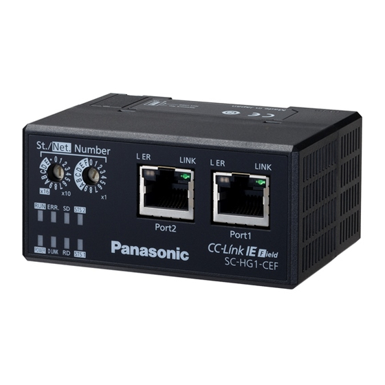
DESCRIPTION OF PARTS
16
15
14
13
Name
Station No. / Network No.
1
setting switch
2
Port2 L ER indicator (Yellow)
3
Port2 LINK indicator (Green)
4
Port1 L ER indicator (Yellow)
5
Port1 LINK indicator (Green)
6
Port1
7
Port2
8
Male connector
9
STS2 indicator (Red)
10
STS1 indicator (Green)
11
RD indicator (Green)
12
D LINK indicator (Green)
13
Power indicator (Green)
14
ERR. indicator (Red)
15
RUN indicator (Green)
16
SD indicator (Green)
1 pc.
1 pc. each
17
Mode setting switch (Note 1)
1 pc.
Notes: 1) For the operation mode settings, refer to "
2) Unless otherwise specified, all functions are used in normal mode.
5
MOUNTING AND CONNECTIONS
Mounting procedure
1. Hook the rear of the mounting part onto
the 35mm width DIN rail.
2. While pressing the rear of the mounting
part down on the 35mm width DIN rail,
fit the front of the mounting part onto
the DIN rail.
Removal procedure
1. Grasp the product and push forward.
2. Lift the front to remove.
Note: If you attempt to lift the front without pushing the product forward, you may bend the hook on the back of the
mounting part.
Connection procedure
● This product must be connected to a controller.
● Up to 15 controllers (one master controller and 14 slave controllers) can be connected
to the product.
● Always shut OFF the power before connecting the product to or disconnecting
the product from a controller. Risk of damage to the product and controller if con-
nected with the power ON.
● I nsert the male connector firmly into the female connector. Risk of damage to the
product and controller if not connected completely.
● To connect the product to a controller, the units must be mounted on a DIN rail.
Attach end plates MS-DIN-E (optional) or commercially available fittings so as to
enclose the connected units at the ends.
● For cautions on using controllers, refer to the manual for the controller.
1. Mount the product on a 35mm width DIN rail.
2. Remove the connector cover from the
controller. (Note)
3. Slide the product so that it directly contacts
the controller.
1
2
3
4
5
6
7
12
11
10
9
8
Rotary switch for setting a station number or network number.
[Factory setting: Station No.1, Network No.1]
Functions are changed by means of the operation mode set with the mode
switch. (Note 1)
Lights up when abnormal data is received.
Lights up during link-up.
Lights up when abnormal data is received.
Lights up during link-up.
RJ45 connector for CC-Link IE Field connection. Connect an Ethernet cable.
There are no restrictions on the order of Port1 and Port2 wiring.
Connect to a master controller or slave controller. Power is supplied from a master
controller or slave controller through this connector.
• Normal mode (Note 1)
Lights up when a command to the master controller or slave controller results
in an error.
• Network No. setting mode (Note 1)
Lights up when the network number setting is outside the range.
• Normal mode (Note 1)
Lights up during communication with the master controller or slave controller.
• Network No. setting mode (Note 1)
Blinks when network number setting preparation is completed.
Lights up when setting and saving of the network number are completed.
Lights up during data reception.
Lights up during execution of data link (during cyclic transmission).
Blinks during execution of data link (while cyclic transmission is stopped).
Lights up when power is supplied.
Lights up when a communication unit error occurs. Blinks when the station number
is changed after the power is turned ON.
Lights up during normal operation.
Lights up during data transmission.
Sets the operation mode. [Factory setting: Normal mode]
SW No.
Normal mode
Network No. setting mode
6
COMMUNICATION SETTINGS".
2. Press down
17
<Switch cover removed>
Function
1
2
3
4
Not used
OFF
(keep in OFF position)
Not used
ON
(keep in OFF position)
1. Insert
35mm width DIN rail
1. Push forward
2. Lift
Controller - master (Option)
Controllers - slave (Option)
This product
Connector cover
Slide
Advertisement

Related Manuals for Panasonic SUNX SC-HG1-CEF


Summary of Contents for Panasonic SUNX SC-HG1-CEF
- Page 1 DESCRIPTION OF PARTS INSTRUCTION MANUAL CC-Link IE Field Communication Unit for HG Series SC-HG1-CEF CMJE-SCHG1CEF No.0058-67V Thank you very much for purchasing SUNX products. <Switch cover removed> Please read this Instruction Manual carefully and thoroughly for the correct and optimum Name Function use of this product.
- Page 2 2. Insert the connector until you hear a "click" http://panasonic.net/id/pidsx/global sound. Overseas Sales Division (Head Office) 2431-1 Ushiyama-cho, Kasugai-shi, Aichi, 486-0901, Japan Phone: +81-568-33-7861 FAX: +81-568-33-8591 For sales network, please visit our website. PRINTED IN JAPAN © Panasonic Industrial Devices SUNX Co., Ltd. 2017...