
Related Manuals for Panasonic SC-HG1-ETC


Summary of Contents for Panasonic SC-HG1-ETC
- Page 1 EtherCAT-compatible Communication Unit for HG Series SC-HG1-ETC User’s Manual WUME-SCHG1ETC-2 2019.12 panasonic.net/id/pidsx/global...
- Page 2 (MEMO) WUME-SCHG1ETC-2...
-
Page 3: Type Of Manual
Keep this manual in a safe location for reference whenever necessary. Type of Manual The following user’s manuals are available for the SC-HG1-ETC series. Refer to the appropriate manual according to your need. The user’s manuals are also available for download from our website (https://panasonic.net/id/ pidsx/global). -
Page 4: Manual Configuration
Manual Configuration This chapter explains precautions for safe use, terminolo- 1 Before Using This Product gy, package contents, and the name and function of each component. This chapter explains the types and conditions of devices 2 System Configuration that can be connected to this product. This chapter explains the procedures for installation, con- 3 Installation and Setup nection to external devices, and communication setup. -
Page 5: Table Of Contents
3.1 Preparation for Operation ··························································· 3-2 3.2 Installation ··············································································· 3-3 3.2.1 Installing and Removing the SC-HG1-ETC ································ 3-3 3.2.2 Installing and Removing the SC-HG1-ETC and Compatible Devices ··· 3-4 3.2.3 Connecting and Disconnecting the Ethernet Cable ····················· 3-6 3.3 Setup······················································································ 3-8 3.3.1 Station Aliases ·····································································... - Page 6 5 EtherCAT Operating Procedure ······················································ 5-1 5.1 Network Configuration Setup Method ············································ 5-2 5.2 Example of Operating Procedure after Power ON ···························· 5-7 5.2.1 Operation Flow ···································································· 5-7 5.3 Reading Judgment Output ·························································· 5-8 5.4 External Inputs ········································································· 5-8 5.5 Checking Error Information ························································· 5-9 6 Specification and Dimensions ························································...
-
Page 7: Before Using This Product
1 Before Using This Product 1.1 Safety Precautions ···································································· 1-2 1.2 Handling Precautions ································································· 1-3 1.3 Terminology ············································································· 1-5 1.4 Contents of Package ································································· 1-6 1.5 Name and Function of Each Component ········································ 1-7... -
Page 8: Safety Precautions
1.1 Safety Precautions 1.1 Safety Precautions Always observe This section explains important rules that must be observed to prevent personal injury and prop- erty damage. ■ The hazards that may occur if the product is used incorrectly are described and classified by level of harm. -
Page 9: Handling Precautions
1.2 Handling Precautions 1.2 Handling Precautions ■The following symbols are used to indicate safety information that must be observed. Indicates an action that is prohibited. Indicates an action that must be taken. Indicates a matter that requires caution. Information Indicates supplemental information. Reference Indicates reference to details about the subject in question. - Page 10 1.2 Handling Precautions Wiring ● Before wiring or connection work, always make sure that the power is OFF. Failure to do so may result in electric shock or damage. ● When noise generating devices (such as switching regulators and inverter motors) are used around this product, always ground the frame ground (F.G.) terminal of each device sepa- rately.
-
Page 11: Terminology
1.3 Terminology 1.3 Terminology Term Description A master-slave open network communication system using Real-Time EtherCAT Ethernet Cyclic communication A function that transmits data bidirectionally in specified certain cycles Mailbox communica- A handshake communication function that is used to exchange aperiod- System tion (CoE) ic data... -
Page 12: Contents Of Package
1.4 Contents of Package 1.4 Contents of Package The following items are included in the product package. Before using the product, make sure that no items are missing. ● Controller: 1 pc. ● Instruction manual (English / Japanese, Chinese / Korean): 2 pcs. -
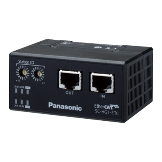
Page 13: Name And Function Of Each Component
1.5 Name and Function of Each Component 1.5 Name and Function of Each Component Name Function Station ID (x16) Rotary switch for setting a station alias. (Note 1) [Station aliases can be set between 00 and FF] Station ID (x1) RJ45 connector for EtherCAT connection. - Page 14 (MEMO) WUME-SCHG1ETC-2...
-
Page 15: System Configuration
2 System Configuration 2.1 System Configuration of This Product ············································ 2-2 2.2 Compatible Devices ·································································· 2-4... -
Page 16: System Configuration Of This Product
Electric power required for this product is supplied from the master controller connected to it. To power supply Controller - Master unit (Option) Connection between slave units To power supply Connect to EtherCAT master device SC-HG1-ETC Controller - Slave unit (Option) (Maximum 14 units connectable) End plate MS-DIN-E (option) WUME-SCHG1ETC-2... - Page 17 HG-SC□ Controller - Slave unit HG-SC□ Controller - Slave unit HG-TC□ SC-HG1-ETC ● If HG-TC series and HG-SC series controllers are used in combination, there are limitations on the functions below. Item Description of limitation Calculation is only performed when the slave unit is the same series as the master unit.
-
Page 18: Compatible Devices
2.2 Compatible Devices 2.2 Compatible Devices This product Product name Appearance Model EtherCAT-compatible SC-HG1-ETC Communication Unit for HG Series Controller ● HG-SC series Type Appearance Model Output High-performance HG-SC101 NPN open-collector transistor type Analog current output HG-SC101-P PNP open-collector transistor... - Page 19 2.2 Compatible Devices ● HG-TC series Type Appearance Model Output High-performance HG-TC101 NPN open-collector transistor type Analog output HG-TC101-P PNP open-collector transistor High-performance HG-TC111 NPN open-collector transistor type Analog output HG-TC111-P PNP open-collector transistor Wire-saving type HG-TC113 ― ● When connecting slave units to the master unit, connect only NPN output type units or only PNP output type units.
- Page 20 (MEMO) WUME-SCHG1ETC-2...
-
Page 21: Installation And Setup
3.1 Preparation for Operation ··························································· 3-2 3.2 Installation ··············································································· 3-3 3.2.1 Installing and Removing the SC-HG1-ETC ································ 3-3 3.2.2 Installing and Removing the SC-HG1-ETC and Compatible Devices ·· 3-4 3.2.3 Connecting and Disconnecting the Ethernet Cable ····················· 3-6 3.3 Setup······················································································ 3-8... -
Page 22: Preparation For Operation
SC-HG1-ETC" Mount and connect this product and controllers on "3.2.2 Installing and Removing the a DIN rail according to the system configuration. Do SC-HG1-ETC and Compatible Devic- not mount end plates. es" Connecting to the power supply Connect the power supply for the master controller. -
Page 23: Installation
3.2 Installation 3.2 Installation 3.2.1 Installing and Removing the SC-HG1-ETC ■ Mounting on a DIN rail Hook the rear of the mounting part onto the 35-mm-wide DIN rail. While pressing down on the rear of the mounting part, insert the front of the mounting part into the DIN rail. -
Page 24: Installing And Removing The Sc-Hg1-Etc And Compatible Devices
3.2 Installation 3.2.2 Installing and Removing the SC-HG1-ETC and Compatible Devices ● Do not pull the connector or cable forcefully. Doing so may damage the connector or break the wires. ● Do not use any tools (such as pliers) to pull out the connector. - Page 25 3.2 Installation Attach end plates MS-DIN-E (optional) with the flat side facing in so as to enclose the con- nected units at the ends. End plate MS-DIN-E (Option) End plate MS-DIN-E (Option) Secure the MS-DIN-E end plates by tightening the screws. Tighten the screws to a torque of 0.3 N·m or less.
-
Page 26: Connecting And Disconnecting The Ethernet Cable
IN or OUT. Insert the connector until it snaps in. Ethernet cable Lock release lever Groove SC-HG1-ETC ■ Disconnecting the Ethernet cable Press on the lock release lever on the Ethernet cable and pull it out. Lock release lever Note ●... - Page 27 3.2 Installation ■ Network connection configuration for EtherCAT The network connection configuration for EtherCAT is classified into line, star, tree, and ring types. Networks can also be configured by mixing the line and star types. <Line type> EtherCAT master device ID:1 ID:2 ID:3...
-
Page 28: Setup
3.3 Setup 3.3 Setup 3.3.1 Station Aliases This product uses the following three methods to set station aliases that enable the master to identify each slave during EtherCAT communications. (1) Configured Station Alias (SII read) This setup method is selected when 0x2001(Station Alias Select) in the object dictionary is set to 1. - Page 29 3.3 Setup ■ Setting station aliases with the station ID switches Station aliases for SC-HG1-ETC communication units can be set within the range between 00 and FFFF (hexadecimal number) by setting the last two digits with the station ID switches and adding the first two digits in 0x2000 in the object dictionary.
- Page 30 (MEMO) 3-10 WUME-SCHG1ETC-2...
-
Page 31: Ethercat Network Communication
4 EtherCAT Network Communication 4.1 Communication Overview ··························································· 4-2 4.1.1 Communication with Master Device·········································· 4-2 4.1.2 Communication between SC-HG1-ETC and Controller ················· 4-3 4.2 Memory Allocation ····································································· 4-4 4.2.1 Object Dictionary ·································································· 4-4 4.2.2 PDO Mapping ······································································ 4-6 4.3 Command Transmission Procedure ·············································· 4-11 4.3.1 Read Command ···································································... -
Page 32: Communication Overview
4.1 Communication Overview 4.1 Communication Overview 4.1.1 Communication with Master Device Data exchange between this product and the master device is performed using process data objects (PDOs). PDO is classified into two types: RxPDO and TxPDO. RxPDO is used to send data from the master to a slave, while TxPDO is used to send data from a slave to the master. -
Page 33: Communication Between Sc-Hg1-Etc And Controller
4.1 Communication Overview 4.1.2 Communication between SC-HG1-ETC and Controller This product automatically converts EtherCAT network communication data to communicate with the controller connected to it. I/O data and settings for the connected controller can be read and written via EtherCAT network communications. - Page 34 4.2 Memory Allocation 4.2 Memory Allocation 4.2.1 Object Dictionary INDEX Subindex Name Type Access Description (HEX) (HEX) 1000 Device type 1001 Error register Stores an AL Status Code error 1008 Manufacturer device name Product name 1009 Manufacturer hardware version VS Hardware version 100A Manufacturer software version VS...
- Page 35 4.2 Memory Allocation INDEX Subindex Name Type Access Description (HEX) (HEX) 1600 Number of entries Receive 0 to 254 PDO mapping 1 1st receive PDO mapped Refer to “4.2.2 PDO Mapping” 1A00 Number of entries Transmit 0 to 254 PDO mapping 1 1st transmit PDO mapped Refer to “4.2.2 PDO Mapping”...
- Page 36 4.2 Memory Allocation 4.2.2 PDO Mapping <Input data - TxPDO (SC-HG1-ETC → Master)> Mapping object Application object INDEX Name INDEX Type Description 1A00:01 Send Complete 6000:01 BOOL Command response: Transmission complete 1A00:02 Command Err Flag 6000:02 BOOL Command response: Error flag...
- Page 37 4.2 Memory Allocation Mapping object Application object INDEX Name INDEX Type Description 1A00:2B Output2 Unit11 6003:0B BOOL Judgment output 2: Slave unit 10 1A00:2C Output2 Unit12 6003:0C BOOL Judgment output 2: Slave unit 11 1A00:2D Output2 Unit13 6003:0D BOOL Judgment output 2: Slave unit 12 1A00:2E Output2 Unit14 6003:0E...
- Page 38 4.2 Memory Allocation Mapping object Application object INDEX Name INDEX Type Description 1A00:5E Output Err Unit14 6006:0E BOOL Error output: Slave unit 13 1A00:5F Output Err Unit15 6006:0F BOOL Error output: Slave unit 14 1A00:60 Output Err CommunicationUnit 6006:10 BOOL Error output: Communication unit 1A00:61 Response Unit1 6007:01...
- Page 39 4.2 Memory Allocation <Output data - RxPDO (Master → SC-HG1-ETC)> Mapping object Application object INDEX Name INDEX Type Description 1600:01 Send Command 7000:01 BOOL Command request: Transmission request 1600:02 Write Flag 7000:02 BOOL Command request: Write flag 1600:03 Non use...
- Page 40 4.2 Memory Allocation Mapping object Application object INDEX Name INDEX Type Description 1600:2F Non use 7003:10 BOOL Unused 1600:30 External Input3 Unit1 7004:01 BOOL External input 3: Master unit 1600:31 External Input3 Unit2 7004:02 BOOL External input 3: Slave unit 1 1600:32 External Input3 Unit3 7004:03...
-
Page 41: Command Transmission Procedure
4.3 Command Transmission Procedure 4.3 Command Transmission Procedure You must send commands when checking controller operating statuses or changing settings. 4.3.1 Read Command If the read command is sent, operating statuses or settings will be returned from each unit (con- troller). - Page 42 4.3 Command Transmission Procedure RxPDO Name Description 1600:40 Command Request Unit1 Command request sensor: Master unit 1600:41 Command Request Unit2 Command request sensor: Slave unit 1 1600:42 Command Request Unit3 Command request sensor: Slave unit 2 1600:43 Command Request Unit4 Command request sensor: Slave unit 3 1600:44 Command Request Unit5...
- Page 43 4.3 Command Transmission Procedure TxPDO Name Description Check that the command has 1A00:01 Send Complete Command response: Transmission complete been completed 1A00:02 Command Err Flag Command response: Error flag successfully. 1A00:03 Non use Unused If a communication 1A00:08 Non use Unused error flag is set, 1A00:09...
- Page 44 4.3 Command Transmission Procedure TxPDO Name Description 1A00:72 Response Data Unit1 Response data: Master unit 1A00:73 Response Data Unit2 Response data: Slave unit 1 1A00:74 Response Data Unit3 Response data: Slave unit 2 1A00:75 Response Data Unit4 Response data: Slave unit 3 1A00:76 Response Data Unit5 Response data: Slave unit 4...
-
Page 45: Write Command
4.3 Command Transmission Procedure 4.3.2 Write Command The transmission procedure for the write command is the same as that described in “4.3.1 Read Command”. Set the command data (parameter settings) to be sent in 1600:51 to 1600:5F and then set the write flag in 1600:02. - Page 46 4.3 Command Transmission Procedure RxPDO Name Description 1600:51 Command Data Unit1 Command data: Master unit 1600:52 Command Data Unit2 Command data: Slave unit 1 1600:53 Command Data Unit3 Command data: Slave unit 2 1600:54 Command Data Unit4 Command data: Slave unit 3 1600:55 Command Data Unit5 Command data: Slave unit 4...
-
Page 47: Command List
4.4 Command List 4.4 Command List 4.4.1 HG-S Series Command List The following table shows the command parameters that are used to read and write controller settings and statuses and to send operation commands to controllers. For details, refer to the “HG-S User’s Manual”. Attributes R: Read, W: Write, R/W: Read/Write Command Attribute... - Page 48 4.4 Command List Command Attribute Name Response/Setting parameter Integer indicating minimum resolution units of controller. Minimum value during P-P 0x0023 If the measurement mode is not P-P or P-P/2, a measurement judgment value is output. -1999999 to 1999999 0x0024 to 0x003F System reserved Do not use.
- Page 49 4.4 Command List Command Attribute Name Response/Setting parameter 2nd point calibration execution Acquire the 2nd point measurement value. 0x0054 (CL.SET2) Specify "0". Integer indicating minimum resolution units of 1-point teaching tolerance 0x0055 controller. setting (TOL<±>) -1999999 to 1999999 1st point teaching execution Execute 1st point of teaching.
- Page 50 4.4 Command List Command Attribute Name Response/Setting parameter Integer indicating minimum resolution units of 0x0105 R/W Self trigger level (SLF.LV) controller. -1999999 to 1999999 Integer indicating minimum resolution units of 0x0106 R/W Static width (DLY.WD) controller. -1999999 to 1999999 Self trigger delay timer 0x0107 Delay time: 0 to 9999ms (DLY.TIM)
- Page 51 4.4 Command List Notes: 1) Usable ASCII character codes (0x20 is a “space”) 1st digit F E D C B A 9 8 7 6 5 4 3 2 1 0 > < 9 8 7 6 5 4 3 2 1 0 4 O N M L K J I H G F E D C B A Z Y X W V U T S R Q P 2) This function can be used on HG-SC series controllers manufactured in February 2019 and later.
-
Page 52: Hg-T Series Command List
4.4 Command List 4.4.2 HG-T Series Command List The following table shows the command parameters that are used to read and write controller settings and statuses and to send operation commands to controllers. For details, refer to the “HG-T User’s Manual”. Attributes R: Read, W: Write, R/W: Read/Write Command Attribute... - Page 53 4.4 Command List Command Attribute Name Response/Setting parameter Integer indicating minimum resolution units of controller. Maximum value during P-P 0x0022 If the measurement mode is not P-P, a judgment measurement value is output. -1999999 to 1999999 Integer indicating minimum resolution units of controller.
- Page 54 4.4 Command List Command Attribute Name Response/Setting parameter Integer indicating minimum resolution units of Scaling lower limit value 0x004F controller. (ANA.LO) -1999999 to 1999999 1: 0.001 Number of digits displayed 0x0050 2: 0.01 (DIGIT) 3: 0.1 0: Default Calibration selection 0x0051 1: User setting (CAL.SEL)
- Page 55 4.4 Command List Command Attribute Name Response/Setting parameter 0x00A3 to 0x00FF ‒ System reserved Do not use. 0x0100 to 0x0112 ‒ Other model command area Do not use. 0x0113 to 0x02FF ‒ System reserved Do not use. 0: Auto edge detection mode 1: Edge detection mode 0x0300 R/W Operation mode (OP.MODE)
- Page 56 4.4 Command List Command Attribute Name Response/Setting parameter Alarm state selection 0: HOLD (hold previous value) 0x0309 (ALM.CND) 1: ALARM (alarm output) 0x030A to 0x030B System reserved Do not use. 0: Stain check OFF (OFF) 1: Low sensitivity setting ON (LOW) 0x030C R/W Stain check (STA.CHK) 2: High sensitivity setting ON (HIGH)
- Page 57 4.4 Command List Command Attribute Name Response/Setting parameter 0: Normal measured value 1: Calculated value (during calculation) 2: Label 0x031C R/W Display switching mode 3: LOW set value 4: HIGH set value 5: Sensor head measured value 6: Work insertion direction (Note 2) Controller cumulative run time 0x031D Units of 1 hour...
- Page 58 4.4 Command List Command Attribute Name Response/Setting parameter End beam axis adjustment. 0x0364 Beam axis adjustment end Specify "0". 0x0365 to 0x036F System reserved Do not use. bit0 to bit7 : Select a waveform type. 0x00 : Reference waveform 0x10 : Waveform during beam axis adjust- ment 0x11 : Measured waveform bit8...
- Page 59 4.4 Command List Command Attribute Name Response/Setting parameter Obtains four bytes of received light waveform 0x037B Waveform read data 11 data (“Received light intensity 40” to “Received light intensity 43”) Obtains four bytes of received light waveform 0x037C Waveform read data 12 data (“Received light intensity 44”...
- Page 60 4.4 Command List Command Attribute Name Response/Setting parameter Obtains four bytes of received light waveform 0x038E Waveform read data 30 data (“Received light intensity 116” to “Received light intensity 119”) Obtains four bytes of received light waveform 0x038F Waveform read data 31 data (“Received light intensity 120”...
- Page 61 4.4 Command List Command Attribute Name Response/Setting parameter Obtains four bytes of received light waveform 0x03A1 Waveform read data 49 data (“Received light intensity 192” to “Received light intensity 195”) Obtains four bytes of received light waveform 0x03A2 Waveform read data 50 data (“Received light intensity 196”...
- Page 62 4.4 Command List Command Attribute Name Response/Setting parameter Integer indicating minimum resolution units of Measured value at the time of 0x03B2 controller. waveform reading (HEAD.V) -1999999 to 1999999 • Edge position 0 Edge position at the time of bit8 to bit15: 0x00 to 0xFF 0x03B3 waveform reading •...
-
Page 63: Reading Received Light Waveforms
4.5 Reading Received Light Waveforms 4.5 Reading Received Light Waveforms This function is used only for the HG-T series controllers. When reading received light waveforms, select measured waveforms, reference waveforms, or waveforms during beam axis adjustment (Note), so that you can read waveform data and other information. - Page 64 4.5 Reading Received Light Waveforms Received light intensity Judgment level TOP side BOTTOM side Edge position 0 Edge information 1: Rising edge Edge information 2: Only one edge enabled Received light intensity Judgment level TOP side BOTTOM side Edge position 0 Edge position 1 Edge information 1: Falling edge...
-
Page 65: Reading Measured Waveforms
4.5 Reading Received Light Waveforms 4.5.2 Reading Measured Waveforms The following procedure is used to read waveforms. ■ Flowchart of measured waveform reading 1. "Waveform read setting" (WRITE) Select a waveform type (measured waveform). 2. "Waveform read setting" (READ) The command saves the current waveform information into the controller. 3. - Page 66 4.5 Reading Received Light Waveforms ■ Examples of sent / received commands Send the “Waveform read setting” command (WRITE) to set the waveform type. (Command code: 0x0370) Send this command only for the first time after starting the communication unit or when switching the type of the waveform to be read.
- Page 67 4.5 Reading Received Light Waveforms To read the measured value associated with the saved waveform, send the “Measured value at the time of waveform reading[HEAD.V]” command (READ). (Command code: 0x03B2) If the response is normal, the following response data will be returned. Read data Measured value: Measured value:...
-
Page 68: Reading Reference Waveforms
4.5 Reading Received Light Waveforms 4.5.3 Reading Reference Waveforms The following procedure is used to read waveforms. ■ Flowchart of reference waveform reading 1. Waveform read setting (WRITE) Select a waveform type (reference waveform). 2. "Waveform read setting" (READ) The command saves the current reference waveform information into the controller. 3. - Page 69 4.5 Reading Received Light Waveforms ■ Examples of sent / received commands Send the “Waveform read setting” command (WRITE) to set the waveform type. (Command code: 0x0370) Send this command only for the first time after starting the communication unit or when switching the type of the waveform to be read.
- Page 70 4.5 Reading Received Light Waveforms To obtain the measurement range (between the measurement start point and measurement end point), send the “Measurement range acquisition” command (READ) (command code: 0x03B1). If the response is normal, the following response data will be returned. Read data Measurement end point Measurement start point...
-
Page 71: Registering Reference Waveforms
4.6 Registering Reference Waveforms 4.6 Registering Reference Waveforms The following flowchart shows the procedure for reading and registering waveforms to register the reference waveform. To register the reference waveform, you must invoke beam axis adjust- ment mode. ■ Flowchart of reference waveform registration 1. - Page 72 4.6 Registering Reference Waveforms Do not register Register the the reference reference waveform waveform (Note 1) 6. "Reference waveform registration 8. "Beam axis adjustment execution" (WRITE) end" (WRITE) (Note 2) 7. "Reference waveform registration status" (READ) Notes: 1) The inside of the frame indicated by the red dotted lines represents beam axis adjustment mode. 2) Beam axis adjustment mode can be terminated at any procedure step by using “8.
- Page 73 4.6 Registering Reference Waveforms ■ Examples of sent / received commands Send the “Beam axis adjustment startup” command (WRITE). (Command code: 0x0360) Write data “0”. To adjust the beam axis without checking waveforms, go to Step 5-2. Send the “Waveform read setting” command (WRITE) to set the waveform type. (Command code: 0x0370) Send this command only for the first time after starting the communication unit or when switching the type of the waveform to be read.
- Page 74 4.6 Registering Reference Waveforms ● Reading waveforms continuously When continuously reading waveforms with the same waveform ID, repeatedly send the commands described in and subsequent steps. The update interval of compressed waveform information is 64 ms. Leave an interval of at least 1 ms when sending each com- mand.
- Page 75 4.6 Registering Reference Waveforms To check whether the reference waveform has been registered after registering it, send the “Reference waveform registration status” command (READ). (Command code: 0x363) If the response is normal, the following response data will be returned. Read data High Bit15 Bit14...
-
Page 76: Self-Monitoring Function
Communication unit Status information from HG-S series, SC-HG1-ETC HG-T series sensors is transmitted to PLC or PC Sensor Status information is transmit- HG-S series ted to SC-HG1-ETC accord- HG-T series ing to the judgment made by the self-monitoring function 4-46 WUME-SCHG1ETC-2... -
Page 77: Statuses And Measures
4.7 Self-monitoring Function 4.7.2 Statuses and Measures The statuses judged by the self-monitoring function are classified into the following four categories. When the status is “notification”, “caution”, or “fault”, you must check the installation state or maintain or replace the product. Status Description Remarks... - Page 78 4.7 Self-monitoring Function ● HG-TC series For details on Response Parameter adress, refer to “4.4.2 HG-T Series Command List”. measurement alarm Response parameter Measures Error code (Note 1) (Note 1) Sensor head unconnected Status check E200 – Connected sensor head incompati- Status check E230 –...
-
Page 79: Other Precautions
4.8 Other Precautions 4.8 Other Precautions • For the HG-T series controllers, measured values will be temporarily reset during measurement if the following commands are written. Command code Name Remarks 0x001E BANK LOAD execution (LOAD) ― 0x0046 Average count (SPEED) ―... - Page 80 (MEMO) 4-50 WUME-SCHG1ETC-2...
-
Page 81: Ethercat Operating Procedure
5 EtherCAT Operating Procedure 5.1 Network Configuration Setup Method ············································ 5-2 5.2 Example of Operating Procedure after Power ON ···························· 5-7 5.2.1 Operation Flow ···································································· 5-7 5.3 Reading Judgment Output ·························································· 5-8 5.4 External Inputs ········································································· 5-8 5.5 Checking Error Information ························································· 5-9... -
Page 82: Network Configuration Setup Method
5.1 Network Configuration Setup Method This section explains how to set up the parameters for this product. The parameter setting method differs according to the master unit. This section explains a system configuration example that uses Panasonic PLC FP7. ■ System configuration example AFP7CPS41E... - Page 83 5.1 Network Configuration Setup Method ■ EtherCAT communication setup method for the AFP7MC16EC Motion Control Unit Use the motion control unit configuration tool (Control Motion Integrator) to set up EtherCAT communication. From the "Parameter” menu, select "EtherCAT Communication Settings". From Project Explorer, select "16-Axis type FP7 Motion Control Unit” and then right-click. Select "Append Slave"...
- Page 84 5.1 Network Configuration Setup Method In the dialog box, select "Panasonic Corporation, Appliances Company", "AC Servo Driver", and then "MADHT1105BA1” and click the OK button. From Project Explorer, select "Slave_001[MADHT1105BA1]” and then right-click. Select "Append Slave" from the context menu.
- Page 85 Unit", and then "SC-HG1-ETC” and click the OK button. If the ESI file for the SC-HG1-ETC has not been installed in the configuration tool, SC-HG1- ETC will not appear in the list when "Add Slave” is selected. Install the ESI file in advance.
- Page 86 5.1 Network Configuration Setup Method From Project Explorer, select "Salve_002[SC-HG1-ETC]” and then check that "Axis No.” in the "General” tab of "Device Editor” is "Unused". In "UM Address" in the "Variables” tab of "Device Editor", check which UM address of the FP7 CPU unit the PDO object has been assigned to.
-
Page 87: Example Of Operating Procedure After Power On
5.2 Example of Operating Procedure after Power ON 5.2 Example of Operating Procedure after Power ON 5.2.1 Operation Flow This section explains the operating procedure that is used after EtherCAT communications are set up using Control Motion Integrator. To configure axes or register slaves, complete setup beforehand. Turn OFF the FP7 MC unit and servo amplifier Turn ON the servo amplifier... -
Page 88: Reading Judgment Output
External input behaves differently according to the controller settings. For details, refer to the user’s manual of the controller that you use. If either of the external inputs turns ON, the controller will perform ON operations. Controller - Master unit SC-HG1-ETC WUME-SCHG1ETC-2... -
Page 89: Checking Error Information
5.5 Checking Error Information 5.5 Checking Error Information If an error occurs on this product, Bit 10 of 1A00:82 is set. Even if the error state is cleared, this flag is held. To reset the flag, set Bit 10 of 2003:01. Error states can be continuously checked via cyclic communication. - Page 90 (MEMO) 5-10 WUME-SCLG2CEFP-2...
-
Page 91: Specification And Dimensions
6 Specification and Dimensions 6.1. Specifications ·········································································· 6-2 6.2. Dimensions ············································································· 6-3... -
Page 92: Specifications
Maximum number of sensor units Up to 15 controllers (1 master controller and 14 slave controllers) can be that can be connected connected to a single SC-HG1-ETC communication unit. Process data object communication (cyclic communication) Mailbox communication (message communication) CoE... -
Page 93: Dimensions
6.2. Dimensions 6.2. Dimensions Units: mm 43.1 21.2 21.1 10.6 16.6 16.6 21.5 Compatible with 35-mm-wide DIN rail WUME-SCHG1ETC-2... - Page 94 (MEMO) WUME-SCHG1ETC-2...
-
Page 95: Warranty
7 Warranty 7.1 Important Information about Order and Use of This Product ··············· 7-2... -
Page 96: Important Information About Order And Use Of This Product
(1) year from the date of shipment under normal usage in environments commonly found in manufacturing industry. (2) Any Products found to be defective must be shipped to Panasonic Industrial Devices SUNX with all shipping costs paid by Purchaser or offered to Panasonic Industrial Devices SUNX for inspection and examination. - Page 97 When such a use is made by Purchaser, such Purchaser shall indemnify and hold harmless Panasonic Industrial Devices SUNX from any liability or damage whatsoever arising out of or in relation to such use.
- Page 98 (MEMO) WUME-SCHG1ETC-2...
-
Page 99: Maintenance
8 Maintenance 8.1 Maintenance and Inspection ························································ 8-2 8.1.1 Maintenance Precautions ······················································· 8-2 8.1.2 Main Inspection Items ··························································· 8-2... -
Page 100: Maintenance And Inspection
8.1 Maintenance and Inspection 8.1 Maintenance and Inspection 8.1.1 Maintenance Precautions • Before cleaning, always turn the power OFF. • Never use thinner, benzene, or other organic solvents to wipe off dirt or dust. • Use a clean, soft cloth to wipe off any dirt that adheres to the controller. 8.1.2 Main Inspection Items Inspect the product regularly to maintain performance and enable optimum use. -
Page 101: Troubleshooting
9 Troubleshooting 9.1 Error Codes and Solutions ·························································· 9-2 9.2 Solutions to Problems ································································ 9-4... -
Page 102: Error Codes And Solutions
Data failed to be written to internal troller. memory. If the controller does not recover even after the above action is taken, consult your Panasonic representative. Before receiving a response to a re- Resend the command after waiting for a certain time 4095 quest, the user sent a next request. - Page 103 9.1 Error Codes and Solutions Notifica- Code Description Action method tion source A command was received from the host during recovery from a lateral connection error (timeout). 2400 Switch OFF the power, make sure the controllers are connected correctly, and then switch ON the power again.
-
Page 104: Solutions To Problems
In such a case, replace this product. • An error has occurred in Panasonic-specific inter-sensor com- munications. Review the communication method by referring to the error code list. (For example, the sensor specification in the command transmission destination may be incorrect. -
Page 105: Sample Programs
10 Sample Programs 10.1 Assumed System Configuration for the Sample Program ················· 10-3 10.2 Sample Program ····································································· 10-4 10.3 Sample Program Overview ························································ 10-5 10-1... - Page 106 This sample program is used to check the measured values of the HG-S and HG-T sensor heads via the SC-HG1-ETC communication unit when the FP7 series PLC is connected as the host device. Measured values can also be displayed on the Web screen via the FP7 series CPU unit.
-
Page 107: Assumed System Configuration For The Sample Program
Motion control unit AFP7MC16EC is connected to FP7 series CPU unit AFP7CPS41E. This combination of the CPU unit and motion control unit is used as the master. The master unit performs cyclic communications with the SC-HG1-ETC communication unit used as a slave unit via Panasonic’s servo motor amplifier MINAS A6B. -
Page 108: Sample Program
10.2 Sample Program 10.2 Sample Program 10-4 WUME-SCHG1ETC-2... -
Page 109: Sample Program Overview
When a network link with motion control unit AFP7MC16EC is established, device X100 is set. All the values sent by the SC-HG1-ETC communication unit via cyclic communications are simultaneously transferred to the area whose leading device is WL40 and subsequent areas from the specified areas in devices UM7D487 to UM7D4B2. - Page 110 The measured value of the HG-T sensor head that is stored in device DT62 can also be displayed as output waveforms on the PC screen by using the Web server function of the FP7 series CPU unit. For details, refer to the Web Server Function Manual (our website: https://panasonic.net/id/ pidsx/global).
- Page 111 ● The measured value of the HG-S sensor head that is stored in device DT1500 can also be dis- played as output waveforms on the PC screen by using the Web server function of the FP7 series CPU unit. For details, refer to the Web Server Function Manual (our Website: https://panasonic. net/id/pidsx/global).
- Page 112 10.3 Sample Program Overview After 500 ms, device R40 that was set by transferring the measured value of the HG-S sen- sor head to device DT1500 is reset by timer settings. ■ Devices used Device Description Function Web graph refresh timing Internal relay 10-8 WUME-SCHG1ETC-2...
- Page 113 Revision history Revision date Revision item First edition 7/01/2019 ― Commands related to the self-monitoring function were added, Second edition 12/01/2019 “4.7 Self-monitoring Function” added WUME-SCHG1ETC-2...
- Page 114 (MEMO)
- Page 115 (MEMO)
- Page 116 ■ Overseas Sales Division (Head Office): 2431-1 Ushiyama-cho, Kasugai-shi, Aichi, 486-0901, Japan ■ Telephone: +81-568-33-7861 ■ Facsimile: +81-568-33-8591 panasonic.net/id/pidsx/global For sales network, please visit our website. © Panasonic Industrial Devices SUNX Co., Ltd. 2019 December, 2019 PRINTED IN JAPAN WUME-SCHG1ETC-2...