Advertisement
Quick Links
Note:
Lifting the machine in an awkward position or
transporting it in a poorly balanced position could
result in personal injury. When transporting the
machine, assign an adequate number of persons
to the job and ensure that each person can take a
good position of not being excessively loaded.
(mass: approx. 10.5 kg (23-1/4 lb))
I. Accessory parts
No.
Name
1. Post inserter
2. Cover
3. Connector
cover
4. Screw cover
5. Positioning
screw
6. Screw A
(4 x 6 mm)
7. Screw B
(4 x 6 mm)
8. Screw C
(4 x 8 mm)
9. Label A
PI-505
INSTALLATION MANUAL
Shape
Q'ty
1
A07VIXC001DA
1
A10AIXC012DA
1
A07VIXC002DA
4
A10AIXC022DA
2
A07VIXC004DA
3
A07UIXC067DA
1
A092IXC012DA
2
9J08IXC080DA
1
set
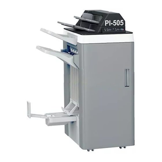
Post Inserter
No.
Name
10. Label B
11. Installation
manual
After unpacking, be sure to get rid of the
packaging materials and keep them out of
the reach of children.
Putting the head in the plastic bag
involves danger of suffocation.
Note:
If the finisher has the punch kit installed, prepare a
short screwdriver that is used in installing the post
inserter.
E-1
Applied Machine: FS-526
Shape
Q'ty
1
1
set
4980IXC019DA
A10A-9550-00
Advertisement

Related Manuals for Konica Minolta PI-505


Summary of Contents for Konica Minolta PI-505
- Page 1 PI-505 Post Inserter INSTALLATION MANUAL Applied Machine: FS-526 Note: Name Shape Q’ty Lifting the machine in an awkward position or 10. Label B transporting it in a poorly balanced position could result in personal injury. When transporting the machine, assign an adequate number of persons to the job and ensure that each person can take a 11.
-
Page 2: Installation Procedures
II. Installation Procedures 3. Remove two screw covers and two screws, and remove the upper cover (small). Note: • When mounting the post inserter, mount it before mounting the finisher to the machine. • When mounting the punch kit at the same time, mount the post inserter first. - Page 3 6. Remove the upper cover (large). 9. Install two positioning screws furnished with the post inserter at the locations as shown in the illus- tration. A10AIXC004DA 7. Install two of the screws that were removed at step 4 at the locations as shown in the illustration. A10AIXC008DA Note: Do not use the screw ➂.
- Page 4 12. Secure the post inserter (three screw A’s fur- 14. Attach four screw covers furnished with the post nished with the post inserter). inserter. A07VIXC015DA A10AIXC016DA 15. Mount the finisher to the machine. Note: For the finisher mounting procedures, see installa- tion manual for finisher.
-
Page 5: Label Attachment
III. Label Attachment 2. Open the finisher front door and affix the label B furnished with the post inserter as shown in the 1. Affix the label A furnished with the post inserter to illustration. the post inserter operation section as shown in the illustration. -
Page 6: Paper Size Detection
IV. Paper size detection 1. Plug the power cord into the power outlet and turn on the machine. 2. Display the Service Mode screen. (For details of how to display the Service Mode screen, see the service manual.) 3. Touch “Finisher.” 4.