Siemens FC2005 Programming Manual
Fire alarm
Hide thumbs
Also See for FC2005:
- Installation, operation and maintenance manual (101 pages) ,
- Programming manual (50 pages) ,
- Installation instruction (3 pages)

Related Manuals for Siemens FC2005


Summary of Contents for Siemens FC2005
- Page 1 Fire Alarm Control Panel Model FC2005/FC901 Programming Manual Smart Infrastructure A6V10333724_b_en_-- 2019-12-02...
-
Page 2: Table Of Contents
Programming Manual of FC2005/FC901 TABLE OF CONTENTS INTRODUCTION ····························································································································· 2 INTERFACE ·························································································································· 5 1.1 Communication Port Connector ·································································································· 6 1.2 LEDS, Buzzer and Dedicated Push Buttons ··················································································· 6 1.3 LCD display ···························································································································· 8 USER LEVEL ······················································································································· 11 Login ······························································································································· 13 Logout ·····························································································································... -
Page 3: Introduction
Programming Manual of FC2005/FC901 INTRODUCTION The FC2005/FC901 Fire Alarm Control Panel can be configured on site. In FC2005/FC901 system, all system information is organized with the concept of the hardware tree, detection tree, control tree and dialer group. And the whole workflow of the system configuration and commissioning are also based on that. - Page 4 CityTie/LeaseLine · CTLL is one optional module which can be mounted onto the mainboard of FC2005/FC901. if the module is installed and enabled in the hardware tree, the work mode of this output can be configured to City Tie or Lease Line.
- Page 5 Programming Manual of FC2005/FC901 The dialer group is only used for sending information through DACT. Dialer group groups events of the zones which assigned to it and report events as it self’s. This means if multiple children report the same kind of events, dialer group will only report it once.
-
Page 6: Interface
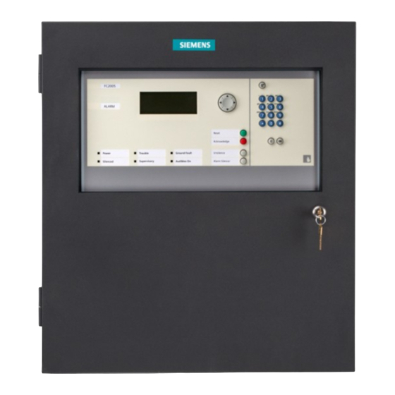
Programming Manual of FC2005/FC901 1. INTERFACE The FC2005 has a buzzer, 7 LEDs, 4 navigational push buttons, 4 push buttons, alphanumeric keypad, 3 menu control buttons (menu, cancel and ok) and a communication port connector. Panel in US Panel in Canada... -
Page 7: Communication Port Connector
Programming Manual of FC2005/FC901 1.1 Communication Port Connector The communication port is connected to the USB port of the computer that has the FXS901-U2 programming tool. This is used to upload and/or download panel configuration if this method of programming is used. - Page 8 Programming Manual of FC2005/FC901 The buzzer operates as follows: Normally OFF – indicates that the system is in normal condition or all events in the system have been acknowledged. ON (200 pulse per minute) – indicates that at least ONE unacknowledged alarm is present in the system.
-
Page 9: Lcd Display
Programming Manual of FC2005/FC901 1.3 LCD display A 160 by 64 dot LCD display is used to display information such as event types, event amount, event location, user level, releasing timer, etc. A back light is included in the display to assure visibility in dim light. To save power, the back light is only activated during a reported event or on operation of a display control button. - Page 10 Programming Manual of FC2005/FC901 1.3.2 LCD display in Canada The text displays in the below graphic and table is just an example. The actual display corresponds to the actual situation. Line Current text Description Alarm Current event type 01/03 Current event/total events...
- Page 11 Programming Manual of FC2005/FC901 1.3.3 Event displaying rules Events are displayed according to the following rules: 1. Events priority: Unacknowledged Alarm > Unacknowledged Supervisory > Unacknowledged Trouble > Acknowledged Alarm > Acknowledged Supervisory > Acknowledged Trouble > Status > Test 2.
-
Page 12: User Level
Programming Manual of FC2005/FC901 2. USER LEVEL The following levels of security protect the system from unauthorized use: L1 (User) – Locked Door L2 (Maintenance) – Locked Door and 4-digit Maintenance Password L3 (Technician) – Locked Door and 4-digit Technician Password... - Page 13 Programming Manual of FC2005/FC901 Table 2-2 Functionality user level list for Canadian panel Items (User) (Maintenance) (Technician) Trouble Signal Silence √ √ √ Acknowledge Switches √ √ √ Automatic Alarm Signal Silence Timer √ Adjust Alarm Signal Silence Operation √...
-
Page 14: Login
Programming Manual of FC2005/FC901 2.1 Login Press “Menu” to display the main menu (Fig. 2-1). Press “↓” to select “Login” and press “OK”, the password entry screen is displayed (Fig. 2-2). Fig. 2-1 Enter the password of maintenance level or technician level and press “OK”, login successfully if the password is correct. -
Page 15: Alphanumeric Character Entry
Programming Manual of FC2005/FC901 3. ALPHANUMERIC CHARACTER ENTRY Numerals entry: Press numeral key, then the numeral is entered. Letters entry: Letters are entered using numerals key. Press down the numeral key which includes the letter (shown at the upper left corner of key), all included letters (upper case and lower case) and the numeral will be orderly and repeatedly displayed. -
Page 16: Operation
Programming Manual of FC2005/FC901 OPERATION HOW TO VIEW PROPERTY Function: This feature allows user to view device property. Steps: Select an element by navigating hardware tree or detection tree (i.e., NAC) (Fig. 4-1). Fig.4-1 Press “OK” to pop out a menu (Fig. 4-2). -
Page 17: How To View History
Programming Manual of FC2005/FC901 HOW TO VIEW HISTORY Function: A panel includes a non-volatile memory recording 1000 system events. Identified alarm, trouble, supervisory, status and other significant events will be recorded along with the date and time of occurrence. This feature allows user to view these events. -
Page 18: How To Disable/Enable
Programming Manual of FC2005/FC901 HOW TO DISABLE/ENABLE Function: This feature allows devices to be disabled for service. A trouble condition is annunciated whenever the disable feature is used and cleared when enabled. Note: Disabled device cannot send any message to controller. -
Page 19: How To Activate/Deactivate
Programming Manual of FC2005/FC901 HOW TO ACTIVATE/DEACTIVATE Function: Any output (i.e., control module, NAC devices etc.) can be activated/deactivated through controller manually. Steps to activate (i.e., NAC activate): Select a device (NAC) by navigating hardware tree (Fig. 7-1). Fig.7-1 Press “Menu” to display the main menu (Fig. 7-2). -
Page 20: How To Do Quick Test
Programming Manual of FC2005/FC901 HOW TO DO QUICK TEST Function: To test installation quickly and easily. The installed device can be activated and NACs can be activated for a short period of time. The quick test menu allows user to configure quick test parameters. User can stop the quick test manually. - Page 21 Programming Manual of FC2005/FC901 Steps: Press “Menu” to display the main menu (Fig. 8-1). Press “→” to select “Oper” submenu, press “↓” to select “Quicktest” (Fig. 8-2) and press “OK”, then the quick test Fig. 8-1 configure screen is displayed (Fig. 8-3).
-
Page 22: How To Do Device Test
Programming Manual of FC2005/FC901 HOW TO DO DEVICE TEST Function: Before doing device test on site, set device as test mode so that alarm will be released faster. Steps for device test: Select a device by navigating hardware tree (Fig. 9-1). -
Page 23: How To Do Short Recovery/ Re-Startup
Programming Manual of FC2005/FC901 HOW TO DO SHORT RECOVERY/ RE-STARTUP Function: short recovery is to recover SLC line short trouble; Re-startup can be clear all events on P2 line and start up P2 line. Steps for short recovery: Short trouble is displayed (Fig. 10-1). -
Page 24: How To Switch On/Off Buzzer
Programming Manual of FC2005/FC901 HOW TO SWITCH ON/OFF BUZZER Function: To turn on/off buzzer. Only user level 3 can do it. Steps: Press “Menu” to display the main menu (Fig. 11-1). Press “→” to select “Oper” submenu (Fig. 11-2), press "↓" to Fig.11-1... -
Page 25: How To Set Time
Programming Manual of FC2005/FC901 HOW TO SET TIME Function: To configure the date and time of the system and the display format. Steps: Press “Menu” to display the main menu (Fig.12-1). Press “→” to select “Oper” submenu (Fig.12-2), press "↓" to Fig.12-1... -
Page 26: How To Change Password
Programming Manual of FC2005/FC901 10. HOW TO CHANGE PASSWORD Function: To change the maintenance and technician password for security. Steps: Press “Menu” to display the main menu (Fig.13-1). Press “→” to select “Oper” submenu (Fig.13-2), press"↓" to Fig.13-1 select "Parameter" and press “OK”, then the edit parameter screen is displayed (Fig.13-3). -
Page 27: How To Do Lamp Test
Programming Manual of FC2005/FC901 11. HOW TO DO LAMP TEST Function: Use lamp test to check whether the LCD, LEDs and the buzzer work. When the lamp test is activated, the LCD, LEDs and the buzzer are all turned on. Lamp test quits automatically when it finishes. -
Page 28: How To Save Configure
Programming Manual of FC2005/FC901 12. HOW TO SAVE CONFIGURE Function: To save changes permanently, otherwise the changes will be lost when the system is restarted. Steps: Press “Menu” to display the main menu (Fig.15-1). Fig.15-1 Press “→” to select "Conf" submenu (Fig.15-2), press “OK” to display the configuration saving window (Fig.15-3). -
Page 29: How To Edit Parameter
Programming Manual of FC2005/FC901 13. HOW TO EDIT PARAMETER Function: To modify parameters of device and panels. See Appendix table 1 for parameters details. Steps: To Select an element (i.e., NAC1) by navigating hardware tree or detection tree (Fig.16-1). Press “OK” to pop out a menu (Fig.16-2). -
Page 30: How To Create/Delete Logic Control
Programming Manual of FC2005/FC901 14. HOW TO CREATE/DELETE LOGIC CONTROL Function: To create/delete logic control among detection group, supervision group and control output group. Steps of creating: Press “Menu” to display the main menu (Fig.17-1). Press “↓” to select “Control” item and press “OK” (Fig.17-2), logic expression screen is displayed (Fig.17-3). - Page 31 Programming Manual of FC2005/FC901 Steps of deleting: Select a logic control which needs to be deleted, then press “Menu” and press “→” to select “Conf” submenu. Press “↓”to select “Delete” and press “OK” (Fig. 17-11), then the deleting confirming screen is displayed (Fig. 17-12). Press “OK” to confirm deleting the logic control or press ”C”...
- Page 32 Programming Manual of FC2005/FC901 Fig.17-11 Fig.17-12 A6V10333724_b_en_-- 31|63...
-
Page 33: How To Edit Logic Control
Programming Manual of FC2005/FC901 15. HOW TO EDIT LOGIC CONTROL Function: To edit logic control. Steps: Press “Menu” to dispaly the main menu (Fig.18-1). Press “↓” to select “Control” item (Fig.18-2) and press “OK”, all Fig.18-1 logic expressions are listed (Fig.18-3) . - Page 34 Programming Manual of FC2005/FC901 Fig.18-6 Fig.18-7 Fig.18-8 Fig.18-9 A6V10333724_b_en_-- 33|63...
-
Page 35: How To Create/Delete Dialer Group
Programming Manual of FC2005/FC901 16. HOW TO CREATE/DELETE DIALER GROUP Function: Dialer Group is used to reduce the number of messages reported to supervising station. For example: if two zones both detect alarm condition but they are close to each other, sending one piece of alarm message will be enough to inform the supervising station, meanwhile, this behavior can reduce costs. - Page 36 Programming Manual of FC2005/FC901 Steps of deleting: To select a dialer group which need to be deleted, press” Menu” Fig.19-6 and press “→” to select “Conf” submenu, to select “Delete” and press “OK” (Fig.19-10), deleting confirming screen is displayed (Fig.19-11). Press “OK” to confirm to delete the dialer group or press”C”...
-
Page 37: How To Assign
Programming Manual of FC2005/FC901 17. HOW TO ASSIGN Function: To assign a channel to a zone for logic control; To assign a zone to cause (OR) for logic control. Steps to assign a zone to cause (OR): Press “Menu” to display the main menu (Fig. 20-1). -
Page 38: How To Get System Version
Programming Manual of FC2005/FC901 18. HOW TO GET SYSTEM VERSION Function: To show system edition, download time of configuration file and modification time. Steps: Press “Menu” to display the main menu, press “↓” to select “About” item (Fig. 21-1). Fig.21-1 Press "OK"... -
Page 39: How To Set System Timer
Programming Manual of FC2005/FC901 19. HOW TO SET SYSTEM TIMER Function: This option allows the user to set the following system timer parameters: Timer Description Value Scope Default Min. Step Reset Inhibit Sets the time the user is prevented form {min:0;max:6;}... - Page 40 Programming Manual of FC2005/FC901 or not. Set if the status events can be removed from event list after it disappears. If it is set as False, Status Self a Status Restoral event will be created and {True;False;} True Restoring appended in event list on the event disappears.
-
Page 41: How To Configure A New System
Programming Manual of FC2005/FC901 20. HOW TO CONFIGURE A NEW SYSTEM After all of the devices, notification appliances and option modules have been installed, check all wiring for grounds, shorts and opens. Confirm all wirings are security and switch power on. Panel will recognized all connected devices and show them under hardware tree. -
Page 42: Appendix 1 Parameter List
Programming Manual of FC2005/FC901 APPENDIX 1 PARAMETER LIST Equipment type Editable item Parameter description Panel Name Name of the panel - FC2005/FC90 Name addition Addition description of the device; max. 20 characters Buzzer on L3 Bool: True (default) / False... - Page 43 Programming Manual of FC2005/FC901 Disable Output Bool: True (default) / False Disable Audiblebase Bool: True (default) / False Annunciator Off Bool: True / False(default) LED Annunciator Off Bool: True / False(default) Printer Off Bool: True / False(default) History Off Bool: True / False(default)
- Page 44 Programming Manual of FC2005/FC901 Line 1 Wire Style Option 1: Class A Option 2: Class B (default) Name Name of the device Name Addition Addition description of the device; max. 20 characters Address Range: 1...50; System assigns one address automatically once a device is added.
- Page 45 Programming Manual of FC2005/FC901 HoldThroughReset Device won’t be reset when press Reset button on the panel. (output channel) Bool: True / False (default) HFPO-11 Name Name of the device Name Addition Addition description of the device; max. 20 characters Address Range: 1...50.
- Page 46 Programming Manual of FC2005/FC901 Silenceable On Available when “Silenceable” (output channel) is set as True. Waterflow Bool: True (default) / False (output channel) HoldThroughReset Device won’t be reset when press Reset button on the panel. (output channel) Bool: True / False (default)
- Page 47 Programming Manual of FC2005/FC901 Isolator Support When set as True, the device should be wired according to the rules for isolator supported. Otherwise, the panel reports trouble. When set as False (default), the device should be wired as polar non-sensitive. Otherwise, the panel reports trouble as well.
- Page 48 Programming Manual of FC2005/FC901 Buzzer Base Powering Available when “ABHW-4B” is selected for “Audible Base Type”: Detection Line Powered NAC Powered AUX/DC Powered (default) Speaker Base Available when “ABHW-4S” is selected for “Audible Base Type”: Powering NAC Powered AUX/DC Powered (default)
- Page 49 Programming Manual of FC2005/FC901 Address Range: 1...50; System assigns one address automatically once a device is added. LED Normal Off Bool: True/ False (default) LED Activation Input Only (default) Input or Output Wire Style Option 1: Class A Option 2: Class B (default)
- Page 50 Programming Manual of FC2005/FC901 ABHW-4B ABHW-4S Buzzer Base Powering Available when “ABHW-4B” is selected for “Audible Base Type”: Detection Line Powered NAC Powered AUX/DC Powered (default) Speaker Base Available when “ABHW-4S” is selected for “Audible Base Type”: Powering NAC Powered...
- Page 51 Programming Manual of FC2005/FC901 Multi Critieria Setting Option 1: Sensitive 1.40%/ft (SmokeHeatSensor) Option 2: Standard 1.80%/ft Option 3: Robust 2.30%/ft (default) Available when “Multi Criteria Usage” is set to “Multi-criteria”. Alarm Verification Bool: True/ False (default) (SmokeHeatSensor) Available when “Multi Criteria Usage” is set to “Multi-criteria”.
- Page 52 Programming Manual of FC2005/FC901 Detection Line Powered NAC Powered AUX/DC Powered (default) Speaker Base Available when “ABHW-4S” is selected for “Audible Base Type”: Powering NAC Powered AUX/DC Powered (default) Turn Off Bool: True/ False (default) Isolator Support When set as True, the device should be wired according to the rules for isolator supported.
- Page 53 Programming Manual of FC2005/FC901 a device is added. LED Normal Off Bool: True/ False (default) LED Activation Input Only (default) Input or Output Audible Base Type Unknown (default) ABHW-4B ABHW-4S Buzzer Base Powering Available when “ABHW-4B” is selected for “Audible Base Type”:...
- Page 54 Programming Manual of FC2005/FC901 XTRI-M a device is added. LED Normal Off Bool: True / False (default) Turn Off Bool: True / False (default) When set as True, the device should be wired according to the rules for isolator supported. Otherwise, the panel reports Isolator Support trouble.
- Page 55 Programming Manual of FC2005/FC901 well. ILED-XC Name Name of the device ILED-XW: Name Addition Addition description of the device; max. 20 characters ILED Channel Silenceable Bool: True (default) / False Silenceable On Bool: True (default) / False Waterflow Device won’t be reset when press Reset button on the panel.
- Page 56 Programming Manual of FC2005/FC901 (Only available for Name Addition Addition description of the device; max. 20 characters UL type panel) Address Range: 1...50; System assigns one address automatically once a device is added. Turn Off Bool: True / False (default)
- Page 57 Programming Manual of FC2005/FC901 (SmokeSensor) Silenceable Bool: True (default) / False (output channel) Silenceable On Available when “Silenceable” (output channel) is set as True. Waterflow Bool: True (default) / False (output channel) HoldThroughReset Device won’t be reset when press Reset button on the panel.
- Page 58 Programming Manual of FC2005/FC901 Turn Off Bool: True / False (default) Silenceable Bool: True (default) / False (ILED Channel) Silenceable On Waterflow Bool: True (default) / False (ILED Channel) HoldThroughReset Device won’t be reset when press Reset button on the panel.
- Page 59 Programming Manual of FC2005/FC901 (Only available for Enable RateOfRise Bool: True / False (default) ULC type panel) STRI-D Name Name of the device STRI-S Name Addition Addition description of the device; max. 20 characters (Only available for Address Range: 1...50; System assigns one address automatically once ULC type panel) a device is added.
- Page 60 Programming Manual of FC2005/FC901 Charger Disable True: use external charger False (default): use onboard charging circuit GFault Disable Ground fault supervisory Bool: True / False (default) Turn Off Bool: True / False (default) DACT connection Option 1: Pulse Dialing Mode...
- Page 61 Programming Manual of FC2005/FC901 user selects Stub A in the tool, the device must connect to Stub A (primary port) as well on the panel, otherwise, error occurs. It doesn’t matter if the wiring style is Class A. FT2007: Name...
- Page 62 Programming Manual of FC2005/FC901 on the Stub A (primary port) on the panel, otherwise, the UFP device will not be detected by the panel. It doesn’t matter if the wiring style is Class A. CTLL Option 1: CityTie (default) Work Mode...
- Page 63 Programming Manual of FC2005/FC901 Option 3: Supervisory Option 4: Waterflow Option 5: Any User Control Name Name of the control Access level L1, L2, L3 Latching (default) Control Mode Momentary Momentary Duration Range: 1…180 s (sec) Only available when Control Mode is set to “Momentary”.
- Page 64 Programming Manual of FC2005/FC901 OR (default) CauseCalculation Dialer group Name Name of the dialer group Range: 1…500. System assigns one address automatically Address once a group is added. "generic fire alarm", "smoke detector alarm", "water flow alarm", Contact Id Alarm Code "heat detector alarm", "manual station alarm", "duct alarm", “co...
-
Page 65: Appendix 2 Trouble-Shooting
Status: FXS901-U2/U3 reports Version Mismatch when user performs download Firmware or Configuration or upload Configuration. Possible Causes: The sales channel of FXS901-U2/U3 and FC2005/FC901 is incompatible. You can not use FXS901-U2 to communicate with FC901 and vice versa. Handling: Find a compatible version FXS901-U2/U3 and try again. - Page 66 © 2011 Copyright by Beijing Siemens Cerberus Electronics Limited No.1, Fengzhidonglu, Xibeiwang, HaiDian District, Beijing Siemens Cerberus Electronics Ltd. Beijing, 100094, China Data and design subject to change without notice. Tel: +10 6476 8806 Fax: +10 6476 8899 Doc. No.