
Related Manuals for Siemens FC10


Summary of Contents for Siemens FC10
-
Page 1: Operating Instructions
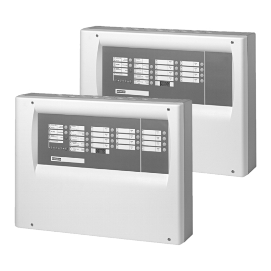
FC10 Fire detection control unit Operating instructions Fire & Security Products Siemens Building Technologies... - Page 2 Sous réserve de modifications techniques et de la disponibilité. © 2004 Copyright by Siemens Building Technologies AG Wir behalten uns alle Rechte an diesem Dokument und an dem in ihm dargestellten Gegenstand vor. Der Empfänger anerkennt diese Rechte und wird dieses Dokument nicht ohne unsere vorgängige schriftliche Ermächtigung ganz oder teilweise Dritten zugänglich machen oder außerhalb des Zweckes verwenden, zu dem es ihm übergeben worden ist.
-
Page 3: Table Of Contents
Temporarily blocking remote transmission of alarms & faults ....24 Polling event memory ................25 Setting date and time ................26 Maintenance ..................27 Important notes ..................27 Check detector network ................27 Check control unit ...................28 Simulate alarm ..................28 Simulate fault ..................29 Troubleshooting..................30 Siemens Building Technologies 007995_a_en_--.doc Fire & Security Products 04.2004... -
Page 5: About This Document
Disregard of the safety regulations Before they are delivered, products are tested to ensure they function correctly when used properly. Siemens disclaims all liability for damage or injuries caused by the incorrect application of the instructions or disregard of warnings of danger contained in the documentation. -
Page 6: Safety Regulations
Disconnect the module from the power supply. 2.1.3 Classification and meaning of additional symbols Tips and information. Refers to extremely important or critical decisions to be taken into account before continuing the work. Siemens Building Technologies 007995_a_en_--.doc Fire & Security Products 04.2004... -
Page 7: Safety-Relevant Working Instructions
Inform the alarm and fault receiving stations connected to the system (e.g. fire brigade) before carrying out the tests. Activate fire control installations for test purposes only when you are sure that no damage will be caused. Siemens Building Technologies 007995_a_en_--.doc Fire & Security Products 04.2004... -
Page 8: System Overview
(e.g. fire brigade) via a remote transmission device (RT). In case of fault, it is also possible to inform an external receiving station. Siemens Building Technologies 007995_a_en_--.doc Fire & Security Products 04.2004... -
Page 9: System Configuration
Maximum operating time without mains ______ h supply Building plan handed over on: __________ by: _________ System configuration Tab. 1 Siemens Building Technologies 007995_a_en_--.doc Fire & Security Products 04.2004... -
Page 10: Structure And Function
General entries, e.g. Acknowledge Zone keys Allocate selected functions to the zone; one key is allocated to each zone Numeric keys Entry of numeric values Function of the keys Tab. 3 Siemens Building Technologies 007995_a_en_--.doc Fire & Security Products 04.2004... -
Page 11: Function
The service technician has handed over a building plan to you, in which the alloca- tion of the detectors to the detector zones is indicated. Siemens Building Technologies 007995_a_en_--.doc Fire & Security Products... -
Page 12: Operating Modes
At maximum two switchover times may be defined. Automatic switchover between summer time and winter time With fire detection systems with an indicator module, switching over between summer time and winter time can be effected automatically. Siemens Building Technologies 007995_a_en_--.doc Fire & Security Products 04.2004... -
Page 13: Alarms
During V1 the staff may acknowledge the alarm. During V2 the staff may check whether it is a real fire or false alarm. Process: Zone type internal Alarm is only indicated on the control unit, it is not transmitted to the fire brigade. Siemens Building Technologies 007995_a_en_--.doc Fire & Security Products 04.2004... -
Page 14: Faults
When the fault is not acknowledged within V1, the remote transmission function is activated. Faults are possibly always immediately transmitted to the receiving station (see section 'Configura- tion'. Siemens Building Technologies 007995_a_en_--.doc Fire & Security Products 04.2004... -
Page 15: Indicator Module (On Option)
For this reason, regularly perform the following maintenance work: Test LED on the control unit Test detectors Test fire alarm devices such as horns or flash-lights Test remote transmission Check alarm organization Siemens Building Technologies 007995_a_en_--.doc Fire & Security Products 04.2004... -
Page 16: Operation
The LED 'Operating access' lights up and the operation is enabled. 2. To block operating level 2 again, take the key from the lock. The LED 'Operating access' no longer lights up. Siemens Building Technologies 007995_a_en_--.doc Fire & Security Products... -
Page 17: Set Operating Mode 'Manned'/'Unmanned
When switching from 'Unmanned' to 'Manned', it is possible to have the next switchover time from 'Manned' to 'Unmanned' indicated (e.g. 18:00; see table 'Configuration'). Siemens Building Technologies 007995_a_en_--.doc Fire & Security Products 04.2004... -
Page 18: Operation In Case Of Alarm With Alarm Organization ('Manned')
The control unit is in normal operation again. Note on control units with an indicator module The remaining delay periods V1 and V2 are indicated on the display. All other indications are overwritten during the alarm. Siemens Building Technologies 007995_a_en_--.doc Fire & Security Products 04.2004... - Page 19 Alarm (red LEDs are flashing rapidly) Press red key Read off fire location Go to the fire location Decide! No fire Fire Back to the Activate next control unit manual call point Press green Siemens Building Technologies 007995_a_en_--.doc Fire & Security Products 04.2004...
-
Page 20: Activating An Evacuation
3. To cancel the evacuation, press the key 'Evacuation' again. The LED 'Evacuation' no longer lights up. The fire alarm devices (e.g. horns) are deactivated The control unit is in normal operating condition again. Siemens Building Technologies 007995_a_en_--.doc Fire & Security Products 04.2004... -
Page 21: Switching Off System Parts
3. To switch the zone on again, press the desired detector zone key twice. The yellow zone LED no longer lights up. The zone is switched on again. Siemens Building Technologies 007995_a_en_--.doc Fire & Security Products 04.2004... -
Page 22: Temporarily Switching Off Alarm Devices
3. To switch the fire control installations on again, press the key 'Control Dis- able/Enable' twice. The yellow LED 'Controls' no longer lights up. All fire control installations are switched on again. Siemens Building Technologies 007995_a_en_--.doc Fire & Security Products 04.2004... -
Page 23: Switching Fire Control Installations And Alarm Devices Temporarily Off
3. To enable the remote transmission of faults again, press the key 'RT-FAULT Disable/Enable'' three times. The yellow LED 'RT-FAULT' no longer lights up. The remote transmission of faults is enabled again. Siemens Building Technologies 007995_a_en_--.doc Fire & Security Products 04.2004... -
Page 24: Temporarily Blocking Remote Transmission Of Alarms
3. To switch the remote transmission on again, press the key 'RT-ALARM Dis- able/Enable' once. The yellow LED 'RT-FAULT' and 'RT-ALARM' no longer light up. The remote transmission of alarms and faults is enabled again. Siemens Building Technologies 007995_a_en_--.doc Fire & Security Products 04.2004... -
Page 25: Polling Event Memory
'Part of system OFF' System part has been out of service 'Fault' A fault has occurred in the system 'Evacuation' Evacuation has been activated Meaning of the LED display Tab. 4 Siemens Building Technologies 007995_a_en_--.doc Fire & Security Products 04.2004... -
Page 26: Setting Date And Time
7. Repeat the steps 4 to 6, thus setting the day, the hours and the minutes. 8. Exit the settings with the numerical key '4'. The settings have been stored. The system is in normal operating condition again. Siemens Building Technologies 007995_a_en_--.doc Fire & Security Products 04.2004... -
Page 27: Maintenance
The yellow zone LED and the LED 'Detector test' are no longer flashing. The LED 'Part of system OFF' no longer lights up. The system is in normal operating condition again. Siemens Building Technologies 007995_a_en_--.doc Fire & Security Products 04.2004... -
Page 28: Check Control Unit
5. Check whether the fire control installations have responded correctly. 6. To finish the simulation, press the key 'Acknowledge', then the key 'Reset'. 7. Repeat steps 2 to 5 for all zones. Siemens Building Technologies 007995_a_en_--.doc Fire & Security Products... -
Page 29: Simulate Fault
A fault is simulated. The yellow zone LED is flashing rapidly. The fault sequence has been activated. 4. Check whether the fault sequence is correct. 5. To finish the simulation, press the key 'Reset'. Siemens Building Technologies 007995_a_en_--.doc Fire & Security Products 04.2004... -
Page 30: Troubleshooting
5. Verify whether the mains supply is avail- (point is flashing) able. 6. Contact the service technician. Troubleshooting Tab. 6 When you cannot remedy a fault by means of these operating instructions, contact the service technician. Siemens Building Technologies 007995_a_en_--.doc Fire & Security Products 04.2004... - Page 32 Siemens Building Technologies AG Alte Landstr. 411 CH-8708 Männedorf Tel. +41 1 - 922 6111 Fax +41 1 - 922 6450 www.sbt.siemens.com Document no. 007995_a_en_-- Manual xx Edition 04.2004 Section x...