Honeywell NOTIFIER ID2000 Series Operating Manual
Hide thumbs
Also See for NOTIFIER ID2000 Series:
- Installation & commissioning manual (68 pages) ,
- Manual (147 pages)
Table of Contents
Advertisement
Advertisement
Table of Contents

Related Manuals for Honeywell NOTIFIER ID2000 Series


Summary of Contents for Honeywell NOTIFIER ID2000 Series
- Page 1 ID2000 operating manual 997-434-000-4, Issue 4 May 2010...
-
Page 2: Table Of Contents
ID2000 Series Operating Manual Contents Introduction Associated Documents The ID2000 Panels Cleaning Panel Controls and Indicators Automatic Alarms - what to do Fire Pre-alarm Fault Operator Actions at Panel Introduction 4.1.1 Top Level Display 4.1.2 Passcodes Mute Buzzer Accept Evacuate Silence (and Re-start) Sounders Reset Lamp Test and Display Control... - Page 3 ID2000 Series Operating Manual 4.10.2Print Device Data 4.10.3Display and Re-Print Event Log 4.10.4Printer Control Modes 4.11 Setting the Clock 4.12 Select Day or Night Mode 4.13 Set Language Non-latched Input Operation APPENDIX 1 Status Summary A1-1 to A1-12 997-434-000-4, Issue 4 May 2010...
-
Page 4: Introduction
ID2000 Series Operating Manual Introduction This manual contains operating instructions for the ID2000 Series of Intelligent Fire Detection Panels. Users of this manual are assumed to be working with a panel that has already been installed and configured appropriately for the area under its supervision. 1.1 Associated Documents This manual does not cover details on the installation or configuration of ID2000 Series panels. -
Page 5: Cleaning
ID2000 Series Operating Manual The range of ID2000 Series panels, as supplied by NOTIFIER, are designated as follows: a. ID2000 Basic panel - 2-loop, 16-zone Analogue Addressable Panel. Up to three 2-loop boards can be added, to give a maximum of eight loops. b. -
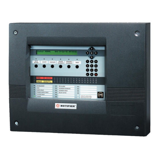
Page 6: Panel Controls And Indicators
ID2000 Series Operating Manual Panel Controls and Indicators STATUS: NORMAL STATUS: NORMAL FRI 09-JUL-04 14:48:40 FRI 09-JUL-04 14:48:40 NOTIFIER ID2000 FIRE ALARM SYSTEM NOTIFIER ID2000 FIRE ALARM SYSTEM MUTE MUTE SILENCE SILENCE RESOUND RESOUND ACCEPT EVACUATE RESET BUZZER BUZZER SOUNDERS SOUNDERS SOUNDERS SOUNDERS... -
Page 7: Automatic Alarms - What To Do
ID2000 Series Operating Manual Automatic Alarms - what to do The following assumes that access passcode 2 is active, or that a user interface door is fitted and is open (refer to Section 4.1.2). 3.1 Fire Automatic panel actions - If the system detects a fire alarm, the panel always does the following automatically: a. -
Page 8: Pre-Alarm
ID2000 Series Operating Manual 3.2 Pre-alarm This is the condition when one or more input devices has signalled a PRE-ALARM to the panel - i.e. a reading which is higher than normal but not yet at the FIRE level. Automatic panel actions: a. -
Page 9: Fault
ID2000 Series Operating Manual 3.3 Fault Automatic panel actions - If the system identifies a fault, the panel always does the following automatically: a. Operates the internal FAULT buzzer. ZONE FAULT ZONE FAULT FAULT DISABLE/TEST DISABLE/TEST b. Flashes one or more amber FAULT lamps, including numbered amber ZONE Fault lamp(s) if appropriate. -
Page 10: Operator Actions At Panel
ID2000 Series Operating Manual Operator Actions at Panel 4.1 Introduction The panel controls and LCD display allow the following actions to be carried out: a. Mute the panel buzzer. b. Accept a fire or fault condition. c. Evacuate (and override delay to outputs, if delay is active). -
Page 11: Top Level Display
ID2000 Series Operating Manual 4.1.1 Top Level Display The LCD display uses a menu structure (shown below) to access the operator functions. When no operator actions are being carried out, the display shows the Top Level display. The menus are accessed from the Top Level display as shown below. -
Page 12: Passcodes
ID2000 Series Operating Manual 4.1.2 Passcodes For some (or if so configured, all) of the actions described in this manual, a passcode is required. The passcode is a code of up to eight digits configured into the panel during commissioning (see ID2000 Series Panel Configuration Manual for details). -
Page 13: Accept
ID2000 Series Operating Manual 4.3 Accept The ACCEPT pushbutton has the following functions in FIRE or FAULT condition: Note: If the panel is in DAY mode (Section 4.12 or may be configured with time-of-day), and ACCEPT is operated during the first investigation time (while the DAY MODE LED is flashing), the delay time before the remote fire output is operated is extended. -
Page 14: Evacuate
ID2000 Series Operating Manual 4.4 Evacuate EVACUATE causes all sounders, etc., which are designated in the pre-programmed EVACUATE pattern, to operate. Note: If an alarm occurs while the panel is in DAY mode (Section 4.12 or may be configured with time-of- day), first operation of EVACUATE will override the delays to the remote fire outputs. -
Page 15: Silence (And Re-Start) Sounders
ID2000 Series Operating Manual 4.5 Silence (and Re-start) Sounders The term ‘silence’, as used throughout this manual, describes a temporary state the panel enters whenever the SILENCE SOUNDERS pushbutton is pressed. While the panel is in this state, a new fire alarm, or pressing the EVACUATE pushbutton, will re-sound all previously silenced sounders. -
Page 16: Lamp Test And Display Control
ID2000 Series Operating Manual 4.7 Lamp Test and Display Control 4.7.1 Lamps Test In Sequence To test the lamps in sequence: 1 With the Top Level menu displayed, press the ‘0’ pushbutton momentarily. The TEST menu is displayed: TEST : 0=Zone/1=Output/2=Lamps: 2 Press the ‘2’... -
Page 17: System Test
ID2000 Series Operating Manual 4.8 System Test To perform a system test press the ‘0’ pushbutton when the Top Level display is present. The TEST menu is displayed: TEST: 0=Zone/1=Output/2=Lamps: These options allow you to: a. Perform a ZONE WALK TEST. b. - Page 18 ID2000 Series Operating Manual System tests are carried out using the menus on the LCD display (see below). To carry out a walk test of sensors or MCPs, select ‘0’ and see Section 4.8.1. To carry out a Control Output test select ‘1’...
-
Page 19: Zone Walk Test
ID2000 Series Operating Manual 4.8.1 Zone Walk Test If the panel is a member of an ID2000 Series panel network, the following is displayed: TEST MODE: SLAVE no. (0=MASTER): n You will need to know the number of the panel at which you wish the test to be conducted. - Page 20 ID2000 Series Operating Manual The following checks allow certain devices to be easily checked for correct operation: a. Analogue sensors - observe that the sensor’s LED changes to steady ON status, returning to pulsing 5 SECONDS mode about 5 seconds after the test condition is removed.
-
Page 21: Control Output Test
ID2000 Series Operating Manual 4.8.2 Control Output Test This test lets you select an individual Control Output and activate it without putting the whole system into alarm or walk test mode. If it is, press the ‘0’ pushbutton as detailed in Section 4.8 above, followed by ‘1’... - Page 22 ID2000 Series Operating Manual 4 The system displays one of the prompts shown below (depending upon whether the module is currently active or not): Mod. (n) - Zone (n) - (type) Switch Module ON ( /X)? ! ! ! ! ! Mod.
-
Page 23: Sensor Automatic Test
ID2000 Series Operating Manual 4.8.3 Sensor Automatic Test Note: This is a maintenance facility only. If you initiate a zone walk test (as described in Section 4.8.1), or if a FIRE is detected elsewhere in the system, while the automatic test is in progress, that test is automatically cancelled if so configured. -
Page 24: Replace (View) Sensor
ID2000 Series Operating Manual 4.8.4 Replace (VIEW) Sensor Each Very Intelligent Early Warning (VIEW) sensor has to be calibrated on first operation with the panel. This calibration is normally carried out automatically for each sensor at one of the following times: a. - Page 25 ID2000 Series Operating Manual 4.8.4.1 Individual VIEW Sensor To recalibrate an individual VIEW sensor: 1 Press ‘0’. The panel display changes as shown below: Select replaced sensor: Choose from ZONE no.: (0=ALL)?0 2 Select the VIEW sensor in the same way as any other individual sensor.
-
Page 26: Disablement And Enablement
ID2000 Series Operating Manual 4.9 Disablement and Enablement It is possible to disable an individual device (see Section 4.9.1), a complete zone (see Section 4.9.2) or all outputs (see Section 4.9.3). [This function is also possible from a remote switch (see Time-of-Day cancellation Section 4.9.4) or configured using the time-of-day of disablements... - Page 27 ID2000 Series Operating Manual There are three modes of operation: a. Disable/Enable an individual device. b. Disable/Enable a complete zone. c. Disable/Enable outputs. These modes are described in detail in the following sections. All operations use the LCD display menu, the structure of which is shown below.
-
Page 28: Individual Device
ID2000 Series Operating Manual 4.9.1 Individual Device To disable or enable an individual device: 1 From the Top Level display, press pushbutton ‘1’. The DISABLE/ENABLEMENT menu is displayed: DISABLE/ENABLEMENT: 0=Individual/ 1=Entire Zone/2=Outputs: 2 Press the ‘0’ pushbutton. If there are already some devices disabled on the system, the panel displays the prompt shown below: Select only from devices ALREADY... -
Page 29: Complete Zone
ID2000 Series Operating Manual Note: If the device is an Output attached to a Control module (logical types CTRL or BELL - but not CDI), and you intend to disable it, you will be asked for a passcode (see Section 4.1.2). Only when this is correctly entered will the disablement be carried out. -
Page 30: Outputs
ID2000 Series Operating Manual For some Network systems (dependent on configuration), there may be a facility, available at the Master Panel only, to perform a disablement or enablement on a complete zone at a different panel on the network. If this feature is available, the procedure is as follows: 1 At the Master Panel, when you enter the DISABLE/ ENABLEMENT procedure and select the ENTIRE... -
Page 31: Complete Zone Via Remote Switch
ID2000 Series Operating Manual 4.9.3.1 Sounder Delays 1 If, and only if, the installer has programmed in one or more sounder delays in the Control Matrix, the following menu is displayed: DISABLE/ENABLEMENT: 0= Individual/ 1= Zone/2= Outputs/3= Sounder Delays: _ 2 Press the ‘3’... -
Page 32: Display, Log And Print
ID2000 Series Operating Manual 4.10 Display, Log and Print This function allows the following: a. Display and or logging of device data (see Section 4.10.1). b. Printing of device data (see Section 4.10.2) c. Display and reprint of the event log (see Section 4.10.3). d. -
Page 33: 1Display And/Or Log Device Data
ID2000 Series Operating Manual 4.10.1 Display and/or Log Device Data (This function is also available from the VDU terminal) This function is used to continuously monitor the data value returned by a sensor or module. Values are shown as a percentage, scaled so that a sensor’s nominal FIRE threshold reading is 100% (i.e. - Page 34 ID2000 Series Operating Manual 6 The display changes to that shown below: LOG/DISPLAY Device: Please select: ↑ ↓ ↑ ↓ Use ↑ ↓ ↑ ↓ ↑ ↓ to step up/down, ! ! ! ! ! to select If you already know the exact or approximate number of the device you want [in the range 1 to the maximum (depends upon the number of loops)], type in that number.
- Page 35 ID2000 Series Operating Manual 9 To return to the ‘standard’ display, press (on VDU press ctrl/X). Alternatively, you may continue to use the up and down arrows to examine other devices’ data. The following facilities are also available: a. LED pulsing option: The LED pulsing option is only available from the panel keypad.
- Page 36 ID2000 Series Operating Manual iii Key in the required recording interval: a whole number of seconds, permitted range 1 to 16383 (just over 4.5 hours), then press . The display changes to that shown below: Sens. (n) Zone (n) (type) Store Capacity (1-4000) Note: If you want to terminate logging for that sensor and release the memory allocated, just press...
-
Page 37: 2Print Device Data
ID2000 Series Operating Manual 4.10.2 Print Device Data (This function is also available from the VDU terminal) This option is the means of obtaining a complete or partial printout of all the devices on the system, including current readings and status. It only works if a printer is installed. To obtain a printout: 1 From the top level display, press pushbutton ‘2’. - Page 38 ID2000 Series Operating Manual 7 If you press just in response to the above question, one of the options shown below is displayed (which one depends upon whether the panel is a network master or not). If you select 1 for ‘YES’ then only disabled devices are printed.
-
Page 39: 3Display And Re-Print Event Log
ID2000 Series Operating Manual 4.10.3 Display and Re-Print Event Log This is a means of examining the most recent past history of events on the system, up to the maximum recording depth of 600 events (once this capacity is reached, new events replace the earliest events). -
Page 40: 4Printer Control Modes
ID2000 Series Operating Manual If a printer is installed, all events are printed out at time of occurrence unless the printer is disabled. However, it is possible to obtain a repeat printout of a selection of all recorded events (up to the maximum of 600) spanning any time period. -
Page 41: Setting The Clock
ID2000 Series Operating Manual 4.11 Setting the Clock This procedure uses the LCD menus. The menu structure is shown below: SETTING CLOCK SETTING CLOCK SET NEW DATE/TIME SET NEW DATE/TIME ADJUST CLOCK SPEED ADJUST CLOCK SPEED SET SUMMER TIME START/END SET SUMMER TIME START/END START CLOCK CANCEL CLOCK RESET... -
Page 42: Select Day Or Night Mode
ID2000 Series Operating Manual b. Set Summer Time Start/End. The following is displayed: Summer Time START Date: 0=None/1=Last Sunday March/2=Define: 0 Select the required option. If you press the ‘2’ pushbutton the following is displayed: Month : n Use the numeric pushbuttons to enter the month and press . -
Page 43: Non-Latched Input Operation
ID2000 Series Operating Manual Non-latched Input Operation This function enables the use of a remotely-placed switch to switch on, temporarily, certain outputs without the need for access to the panel. The function is only available if a remote switch is connected to a loop module which has been configured as an AUXILIARY type input, and this has been linked to specific outputs in the Control Matrix. - Page 44 ID2000 Series Operating Manual Appendix 1 STATUS SUMMARY Status Summary There are nine possible status conditions of the panel. This Appendix describes the system indications for each status condition. The default status is quiescent or NORMAL, which indicates the absence of any other condition. The other conditions are exceptions and more than one at a time may be present.
- Page 45 ID2000 Series Operating Manual PANEL STATUS: NORMAL This is the condition of the panel when it is operational, and there are no uncleared FIREs or FAULTs or PRE- ALARMs, no part of the system is disabled, and no TESTing or CONFIGURATION is being carried out. The LCD displays, indications of the panel and external equipment are as follows: LAMP indications:...
- Page 46 ID2000 Series Operating Manual PANEL STATUS: FIRE This is the condition when one or more input devices has signalled a FIRE to the panel. This condition continues to be shown until cleared by pressing the RESET pushbutton. The occurrence may have been ‘accepted’ at the panel by pressing the ACCEPT pushbutton, if so the status is still ‘FIRE’.
- Page 47 ID2000 Series Operating Manual Circuits Controlled Internally: Sounder Circuits: If not substituted by alternative devices in matrix program, sounder circuits on: STEADY After SILENCE SOUNDERS pressed; may now be: FIRE relay: FAULT relay: External Devices: depending on programmed schedule some or all control modules may be ON, either steady or pulsing.
- Page 48 ID2000 Series Operating Manual PANEL STATUS: PRE-ALARM This condition is when one or more input devices has signalled a PRE-ALARM to the panel - i.e. a reading which is higher than normal but not yet at the FIRE level. This condition continues to be shown until superseded by a higher-priority condition (i.e.
- Page 49 ID2000 Series Operating Manual PANEL STATUS: FAULT This condition occurs for a number of reasons: some arise from incorrect operation of a remote sensor or module, others from incorrect operation of the panel or system as a whole. Also included in this category are ‘POWER SUPPLY FAULT’, which indicates a failure of battery, mains supply or charger circuit, and ‘SYSTEM FAULT’...
- Page 50 ID2000 Series Operating Manual Internal buzzers: if not accepted: Fault buzzer (high-pitched): ON STEADY if accepted or buzzer silenced: Fault buzzer muted: Intermittent - one 0.5 sec pulse ON every 2 minutes Circuits Controlled Internally: Sounder Circuits: Programmed Function FIRE relay: FAULT relay: External Devices: All CONTROL MODULES should be:...
- Page 51 ID2000 Series Operating Manual PANEL STATUS: DEVICES DISABLED This is indicated when some or all of the sensors or modules of the system have been disabled by means of the disablement operation (see Section 4.9 for details). If the panel is a NETWORK MASTER panel this status is shown whenever devices are disabled on the network as a whole.
- Page 52 ID2000 Series Operating Manual PANEL STATUS: EVACUATE This is the condition when the EVACUATE pushbutton has been pressed. The condition continues to be shown until superseded by a higher-priority condition or until cleared by pressing the SILENCE SOUNDERS pushbutton). The LCD displays the message shown below: EVACUATE (date) (time)
- Page 53 ID2000 Series Operating Manual PANEL STATUS: TEST This is the condition of the panel when a Zone has been selected for a walk test, using the appropriate pushbutton sequence (see Section 4.8.1 for details). The TEST condition continues to be shown until superseded by a higher-priority condition or until Test mode is terminated using the appropriate pushbutton sequence.
- Page 54 ID2000 Series Operating Manual PANEL STATUS: ENGINEER This is functionally identical to the NORMAL status except that it indicates that a Passcode has been entered by an authorised engineer in order to program the system. See the ID2000 Series Panel Configuration Manual (997-435-XXX) for further details.
- Page 55 Charles Avenue T: +44 (0) 1444 230 300 Burgess Hill F: +44 (0) 1444 230 888 W. Sussex E: sales@notifierfiresystems.co.uk RH15 9UF www.notifierfiresystems.co.uk local distributor Quality Systems Certificate No. 154 Assessed to ISO9001 Every care has been taken in the preparation of this document but no liability can be accepted for the use of the information therein. Design features may be changed or amended without prior notice.