Table of Contents
Advertisement
Quick Links
Advertisement
Table of Contents

Related Manuals for Honeywell 800-04433V1


Summary of Contents for Honeywell 800-04433V1
- Page 1 800-04433V1 12/10 Rev. A...
-
Page 2: Table Of Contents
Contents General Information ...1 Package Contents ...1 Compatible Fire Panels ...1 Operation ...1 Installation ...1 UL Compliance...1 STEP 1 – Activate the SIM and Setup the Customer Account...2 STEP 2 – Register the Communications Module with AlarmNet ...2 STEP 3 – Determine the Signal Strength and Select a Location ...3 STEP 4 –... -
Page 3: General Information
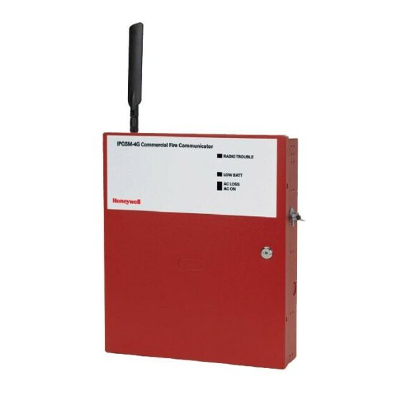
iPGSM-COM Commercial Fire Communicator – Installation and Setup Guide General Information The iPGSM-COM Commercial Fire Communicator includes everything you need to upgrade a commercial fire system that previously reported by POTS to a system that uses the Internet as its primary reporting path, and uses a GSM cellular reporting path as a backup. -
Page 4: Step 1 - Activate The Sim And Setup The Customer Account
iPGSM-COM Commercial Fire Communicator – Installation and Setup Guide STEP 1 – Activate the SIM and Setup the Customer Account The communicator requires a subscriber account (customer account) to be setup with AlarmNet Direct. This is accomplished by registering the communicator's iGSM communications module with AlarmNet. Registering, enables the fire panel to send reports. -
Page 5: Step 3 - Determine The Signal Strength And Select A Location
iPGSM-COM Commercial Fire Communicator – Installation and Setup Guide STEP 3 – Determine the Signal Strength and Select a Location IMPORTANT - Do Not mount this device outdoors. When choosing a suitable mounting location, understand that signal strength is very important for proper operation. - Page 6 iPGSM-COM Commercial Fire Communicator – Installation and Setup Guide Note: Refer to the diagram on page 5, and to the Wiring Diagram on the inside of the back cover of this manual for all wiring information. 5. Mount the Wall Outlet Box to an un-switched facility power outlet and run a conduit to the cabinet. 6.
- Page 7 iPGSM-COM Commercial Fire Communicator – Installation and Setup Guide ANTENNA 50 OHM CABLE CABINET DOOR TO FACILITY GROUND CONDUIT iGSM Comm Module Wiring for Grounds, Power, and RF TRANSFORMER (N8167) NUT, WASHER ANTENNA MOUNTING ADAPTER Display GREEN Dialer Capture Module FOR EXTERNAL ANTENNA 50 OHM MMCX ONLY 7720P PROGRAMMER PORT...
-
Page 8: Step 5 - Program The Communications Module
iPGSM-COM Commercial Fire Communicator – Installation and Setup Guide STEP 5 – Program the Communications Module You must use the 7720P Programming tool to program the iPGSM-COM. When using the 7720P Programming tool, the values given below are for most installations. Press the [#] key to accept the displayed default value (xxx) or enter the new value and press the [#] key for the next prompt. -
Page 9: Step 6 - Configure The Fire Panel
iPGSM-COM Commercial Fire Communicator – Installation and Setup Guide STEP 6 – Configure the Fire Panel 1. Ensure the Telco Fault on the panel is enabled. Then choose a setting that is no higher than 90 seconds (or as close to that) as the panel allows. 2. -
Page 10: Dialer Capture Module Information
iPGSM-COM Commercial Fire Communicator – Installation and Setup Guide Dialer Capture Module Information LED Indicator RED – Steady ON RED – Flashing GREEN – Steady ON GREEN – Blinks every 2 sec. GREEN – Blinks twice every sec. GREEN – Blinks 10 times every sec. GREEN Dialer Capture Module LED Board Information... -
Page 11: Powerboost1 Module Information
iPGSM-COM Commercial Fire Communicator – Installation and Setup Guide PowerBoost1 Module Information LED Indicator STATUS AC power available. (green) ACTIVE Cyclical flashing – normal communications. (green) Repetition of 3 flashes – loss of communications. LOW BATT (yellow) Missing or low battery. One or more trouble conditions exist, such as;... -
Page 12: Igsm Communications Module Information
iPGSM-COM Commercial Fire Communicator – Installation and Setup Guide iGSM Communications Module Information ON – NOT registered with AlarmNet. OFF – Registered with AlarmNet. FAST BLINK – Download session with Compass in progress. SLOW BLINK – In unison with yellow LED, registration in progress. -
Page 13: Ipgsm-Com Specifications
Depth = 3 inches Primary – 120VAC, 60Hz, 0.50A Secondary – 18VAC, 50VA 12V, 7Ah sealed lead acid type (not supplied) Use a Honeywell 712BNP, Yuasa NP7-12 or equivalent. maximum 1A The AC power, backup battery, IP communications, and GSM communications are monitored. - Page 14 iPGSM-COM Commercial Fire Communicator – Installation and Setup Guide NOTES – 12 –...
-
Page 15: Wiring Diagram
All circuits are power limited except the backup battery which is non-power limited. The non-power limited wiring must be separated from the power limited wiring by at least 1/4 inch. If desired, use a Honeywell 955WH Tamper Switch with the 28-2 bracket. WALL OUTLET BOX GREEN Dialer Capture Module... - Page 16 800-04433V1 12/10 Rev. A FCC STATEMENT FCC STATEMENT DOCUMENTATION AND ONLINE SUPPORT WARRANTY For the latest warranty information, please go to: Copyright 2010 Honeywell International Inc. 2 Corporate Center Drive, Suite 100, P.O. Box 9040, Melville, NY 11747 www.honeywell.com/security...