
Related Manuals for Triax CGSD 162


Summary of Contents for Triax CGSD 162
- Page 1 Assembly Instruction CGSD 162 Model Item no. CGSD 162 325033 Version Date 04/2016...
-
Page 2: Table Of Contents
o n t e n t s 1 Safety regulations ....................3 2 General information ..................3 2.1 Scope of delivery ................3 2.2 Meaning of the symbols used ............... 4 2.3 Technical data..................4 2.4 Description ..................4 3 Overview ......................5 4 Installing the SAT IF input distributor ..............6 5 Connecting the SAT IF input distributor ..............7 5.1 Connecting the HF connections ............ -
Page 3: Safety Regulations
a f e t y r e g u l a t i o n s • The standards IEC/EN/DIN EN 50083 resp. IEC/EN/DIN EN 60728 must be observed. • Do not perform installation and service work during thunderstorms. • Assembly, installation and servicing should be carried out by authorised electricians. • Switch off the operating voltage of the system before beginning with assem- bly or service work. • Avoid short circuits! • Observe the relevant standards, regulations and guidelines on the installa- tion and operation of antenna systems. -
Page 4: Meaning Of The Symbols Used
2.2 m e a n i n g t h e s ym b o l s u s e d Important note • Performing works 2.3 t e C h n i C a l data The requirements of the following are met: 2011/65/EU, 2014/30/EU, 2014/35/EU The product fulfils the guidelines and standards for CE labelling. Unless otherwise noted all values are specified as “typical”. Frequency range: ............950 … 2150 MHz SAT IF inputs: ................. -
Page 5: Overview
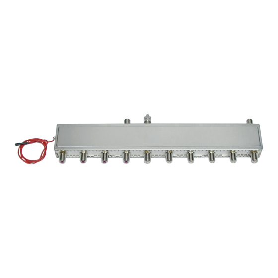
If the loop-through output is not used it must be terminated using the terminator supplied. The DC power feed (max. 800 mA ) is used for the power supply of the LNBs connected. The SAT IF distributor CGSD 162 is designed exclusively for use in the CSE 2800 head-end station. v e r v i e w 8 dB 9-12 dB 9-14 dB LNB power connection Input 1 Input 2 Outputs of input 1 Loop-through output of Outputs of input 2 input 1 with terminator - 5 - CGSD 162... -
Page 6: Installing The Sat If Input Distributor
sat if n s t a l l i n g t h e i n p u t d i s t r i b u t o r Before installing or changing a module or accessory, switch off the head- end station or unplug the power cable from the mains power socket. Installing the SAT IF input distributor take care that no cables are squeezed off or injured. • Remove the front cover and the base plate of the CSE 2800 head-end sta- tion. • Insert the SAT IF input distributor above the output collector so that the LNB power connection is facing the control panel. -
Page 7: Connecting The Sat If Input Distributor
sat if o n n eC ti n g th e i n pu t d is tr i buto r 5.1 C hf o n n e C t i n g t h e C o n n e C t i o n s • Connect the outputs and (page 5) to the appropriate inputs of the... -
Page 8: Connecting The Power Supply
5.2 C o n n e C t i n g t h e p ow e r s u p p ly • Connect plug of the cable of the LNB power connection to one of the contacts “LNB power supply” (800 mA total). LNB power supply - 8 - CGSD 162... -
Page 9: Final Procedures
i n a l pro C e d u res After installing the head-end station, retrofitting accessories or installing mod- ules it is necessary to tighten all cable connections, F terminals and cover screws in order to maintain compliance with current EMC regulations and to ensure a reliable operation. • Securely tighten the cable connections (F connector) using an open-ended spanner (spanner gap 11 mm). • Programme the modules connected and the head-end station if necessary. • Position the breakthroughs in the base plate above the fastening screws • Push the base plate in direction of the arrow and lock it with the locking screw • Tighten the fastening screws • Tighten the nuts of retrofitted F terminals if applicable. • Mount the front cover (see the assembly instructions of the head-end station). - 9 - CGSD 162... - Page 10 For further information and updated manuals go to Copyright © 2016 TRIAX. All rights reserved. The TRIAX Logo and TRIAX, TRIAX Multimedia are registered trademarks or trademarks of the TRIAX Company or its affiliates. All specifications in this guide are subject to change without further notice.