Advertisement
Quick Links
Download this manual
See also:
Mounting Instructions
Advertisement

Related Manuals for Triax TMB 10A


Summary of Contents for Triax TMB 10A
- Page 1 Programmable Multiband Amplifier TMB 10A Ref.: 324575 TMB 10B Ref.: 324576 TMB 10C Ref.: 324578 TMB 10S Ref.: 324577 GB | Mounting instruction TRIAX - your ultimate connection...
- Page 2 TMB 10C • TMB 10S Header (gælder alle engelske sider): TMB Programmable Multiband amplifier TMB 10A – TMB 10B – TMB 10C – TMB 10S General information ..........................2 Safety Instructions ..........................3 Installing the unit........................... 4 t ..........................4 Programming the unit ...........................
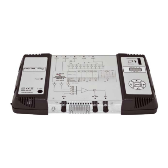
- Page 3 The processing units in the TMB10 range are used to selectively filter analogue and digital UHF channels. These units also couple and amplify VHF programmes according to the satellite band model (IF). TMB10 units have one amplified wide band coupling input; 10 UHF filters, distributed over 3 inputs with programmable bandwidth from 1 to 7 channels (8 to 56 MHz), making it suitable for most situations.
- Page 4 TMB Programmable Multiband Amplifier TMB 10A • TMB 10B • TMB 10C • TMB 10S Important: The unit should only be opened by a qualified technician. • Disconnect the unit before carrying out any work on it, as some powered components are dangerous (risk of electrical shock).
- Page 5 We recommend you install the unit in a sufficiently ventilated place. Natural ventilation must be able to occur through the ventilation grids; leave a minimum space of 15 cm around the unit to ensure maximum ventilation. When installing or cabling the unit, we recommend you disconnect the mains power cable.
- Page 6 TMB Programmable Multiband Amplifier TMB 10A • TMB 10B • TMB 10C • TMB 10S A 4-digit display and a keypad are all you need to programme the unit. Follow the procedure below for configuring the various parameters. CHAN LEVEL...
- Page 7 On powering on, the unit is in standby mode, a light segments flashes across the display: To access the configuration menus, press the menu button until the light segment is under the menu to open and press enter. To summarize: •...
- Page 8 TMB Programmable Multiband Amplifier TMB 10A • TMB 10B • TMB 10C • TMB 10S TMB units have 6 or 10 configurable UHF filters. The UHF filters are distributed over the three inputs UHF1, UHF2, UHF3 as shown below. TMB 10A...
- Page 9 Start menu – input menu Distribution of UHF filters U – Distribution of UHF filters on the inputs UHF1, UHF2 and UHF3; Po – Selection of the remote power supply: 12V or 24V √ enter Select the sub-menu … √ enter Select the distribution of UHF filters …...
- Page 10 TMB Programmable Multiband Amplifier TMB 10A • TMB 10B • TMB 10C • TMB 10S C – Channel menu Start Filter start channel. If the filter is not used, the display shows “--“. CHAN – menu menu The display dot flashes when the filter has a width >...
- Page 11 This function is used to offset the frequency of the filter concerned, to adjust the filters according to the characteristics of the signals received (offset, adjacent channels, etc.). Start The function only acts X esc on the filter selected Select the filter using the keys + and –...
-
Page 12: Setting The Levels
TMB Programmable Multiband Amplifier TMB 10A • TMB 10B • TMB 10C • TMB 10S Setting the levels. There are three types of level setting: • “Manual” setting of output levels (LEVEL menu) • automatic alignment of UHF filter output levels to a value entered by the user. (Auto menu, sub-menu LEU) •... - Page 13 Note: Setting of the levels BI-II / BIII / AUX is not automatic. Start menu AUTO – menu √ enter Select the sub-menu X esc … √ enter Display the value of the output level √ enter … √ enter min.
- Page 14 TMB Programmable Multiband Amplifier TMB 10A • TMB 10B • TMB 10C • TMB 10S TMB units have an SD/MMC interface to save or read configurations and for updating the product. This menu includes 4 sub-menus: • updating of the firmware When the card contains the update file (tm_tmb10.tlp), and the enter key is pressed;...
-
Page 15: Continued On Next Page
CARD Menu Start APL firmware update EHP data memorization InP read configuration files PIN activation and configuration of the PIN code Select the sub-menu The SD/MMC card must be formatted in FAT 16. The files should be placed in the root directory. If the SD/MMC card has no configuration file the display will show noFL during reboot. - Page 16 TMB Programmable Multiband Amplifier TMB 10A • TMB 10B • TMB 10C • TMB 10S Continued from the previous page...
- Page 17 EHP Export Menu Start Insert the SD card The dot flashes when the process begins Select the file to read When the display flashes, the file has been created on the SD card. Press “enter”, to confirm and overwrite the existing file.
- Page 18 TMB Programmable Multiband Amplifier TMB 10A • TMB 10B • TMB 10C • TMB 10S InP Import Menu Insert the SD card Start The dot flashes when the process begins Select the file to read...
- Page 19 • TMB 10S models have two IF amplification channels. The Sat menu is used to configure the remote power supply of the LNB (OFF / 13 /17 V ), to activate the 22kHz generator and the 9dB equalizer. Start menu SAT –...
- Page 20 TMB Programmable Multiband Amplifier TMB 10A • TMB 10B • TMB 10C • TMB 10S Diagram TMB-10A Unit BI-FM BIII-DAB UHF1 UHF2 Frequency range 47÷108 174÷230 47÷862 470÷862 UHF filter setting – Gain (typical) Attenuator 0…20 0…20 0…20 0…20 Noise Max.
- Page 21 Diagram TMB-10B Unit BI-FM BIII-DAB UHF1 UHF2 UHF3 Frequency range 47÷108 174÷230 47÷862 470÷862 – UHF filter setting – – – – Gain (typical) Attenuator 0…20 0…20 0…20 0…20 Noise Max. Input level dBµV Max. Output level* dBµV *DIN 45004B...
- Page 22 TMB Programmable Multiband Amplifier TMB 10A • TMB 10B • TMB 10C • TMB 10S Diagram TMB-10C *DIN 45004B...
- Page 23 Diagram TMB-10S Unit BI-FM BIII-DAB UHF1 UHF2 UHF3 Frequency range 47÷108 174÷230 47÷862 470÷862 950÷2150 – UHF filter setting – – – – Gain (typical) Attenuator 0…20 0…20 0…20 0…20 0…20 Noise Max. Input level dBµV Max. Output level* dBµV *DIN 45004B...
-
Page 24: Power Supply
TMB Programmable Multiband Amplifier TMB 10A • TMB 10B • TMB 10C • TMB 10S TMB-10C Name TMB-10A TMB-10B TMB-10S Units 324578 Reference / part number 324575 324576 324577 Number of inputs AMPLIFICATION 80/80 Max. VHF/UHF input level BI/FM input gain...