
Related Manuals for Triax GHV 500 Series


Summary of Contents for Triax GHV 500 Series
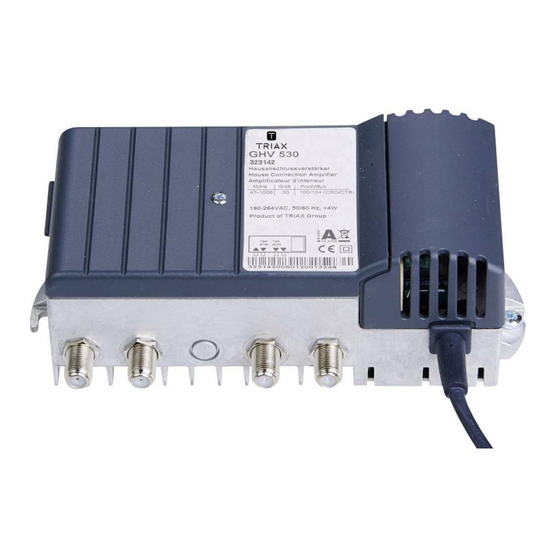
- Page 1 Bedienungsanleitung Hausanschlussverstärker Model Item no. GHV 500 Serie 892020 triax.com Version 02 - 2013...
- Page 2 Alle HF-Anschlüsse sind handmontierte F-Buchsen -20dB Testbuchsen am Ein– und Ausgang Wirksamer ESD– und Surge-Schutz Energieeffizientes Schaltnetzteil 190-264 VAC, 50/60 Hz mit Euro- Netzstecker © Copyright © Triax A/S Kopien und Vervielfältigungen nur mit Genehmigung des Urhebers Deutsch GHV 500 Serie...
-
Page 3: Table Of Contents
Inhaltsverzeichnis Inhaltsverzeichnis Seite 1. Einführung 1.1 Kurzbeschreibung 1.2 Wer diese Anleitung lesen sollte 1.3 Abkürzungen und Symbole 1.4 Gewährleistung 2 . Sicherheitshinweise 2.1 Begriffserläuterungen 2.2 Bestimmungsgemäβe und sachwidrige Verwendungen 2.3 Sicherheitsanforderungen 3. Montage 3.1 Örtliche Gegebenheiten 3.2 Montage 4. Einstellungen 4.1 Verstärker öffnen 4.2 Übersicht 4.3 Einstellmöglichkeiten... -
Page 4: Einführung
Einführung 1 Einführung Hausanschlussverstärker für kleinere Gebäudeeinheiten. 1.1 Kurz– Alle wichtigen Funktionseinheiten wie Vorverstärker und die zugehörigen Stellglieder beschreibung sind vollständig auf der Leiterplatte implementiert und können für die jeweilige Anwen- dung vor Ort konfiguriert werden. Vorverstärkereinstellungen (Dämpfung) über Drehschalter einstellbar in 1dB Stufen (GHV 520) und 1,5dB Stufen (GHV 530) 1.2 Wer diese Diese Anleitung richtet sich an Techniker, Installateure oder eingewiesene Personen, die... -
Page 5: Sicherheitsanforderungen
Montage VORSICHT: 2.3 Sicherheits- Die Sicherheitsanforderungen nach EN 60728-11 sind unbedingt zu beachten. anforderungen Schalten Sie vor Arbeiten an elektrischen Anlagen immer den Stromkreis ab. Lassen Sie einen evtl. notwendigen elektrischen Anschluss grundsätzlich vom Fachmann anbringen. Führen Sie Installationen oder Servicearbeiten nie bei Gewitter durch. ... -
Page 6: Einstellungen
Einstellungen 4. Einstellun- 4.1 Verstärker Entfernen Sie den Gehäusedeckel mittels Zentralschraube D (siehe Abb. 1) öffnen 4.2 Übersicht Abb. 2 Innenansicht Einstellelement—Dämpfung Messbuchse HF-Ausgang, -20dB Drehschalter HF-Eingang HF-Ausgang ... -
Page 7: Einstellmöglichkeiten
Einstellmöglichkeiten Konfigurieren Sie den Verstärker durch Einstellung des Drehschalters wie 4.3 Einstell- folgt: möglich- keiten Siehe Vor- Einstellelement Vorwärtsberiech Einstell-bereich Abb. 3 einstellung Brücken, Abb. Pegelsteller (Eingang) 0-15 dB (GHV520) 0 dB Drehschalter In 1 / 1,5dB-Schritten 0-22,5 dB (GHV 530) 4.4 Einstell- element anpassen... -
Page 8: Technische Daten
Schutzklasse Gewicht Reperatur innerhalb der Garantiezeit nur über Ihren Fachhändler oder über 6. Wartung / das Triax-Service-Center: Tel. 0900/100 15 55 Service (49 Cent/Minute, für Mobilfunknetze können andere Preise gelten) Dieses Produkt ist nach seiner Verwendung entsprechend den aktuellen 7. Entsorgung Entsorgungsvorschriften Ihres Landkreises/Landes/Staates als Elektro- nikschrott einer geordneten Entsorgung zuzuführen. - Page 9 User Guide House Distribution Amplifier GHV 500 Series...
- Page 10 1 x Amplifier with rotary switch 1 x User Guide The GHV 500 Series is a low noise coaxial House Distribution Amplifier, for use in smaller to medium CATV distribution networks in multi dwelling houses. The GHV 500 Distribution Amplifier Series all share a modular design with Rotary switch for readable, easy and reproducible setting of attenuation maintaining a non-breakable signal path to avoid down-time.
- Page 11 Table of Contents Table of Contents Page 1. Introduction 1.1 Description 1.2 Who should read this? 1.3 Abbriviations and Symbols 1.4 Warranty 2 . Security 2.1 Important 2.2 Requirements and wrong handling 2.3 Security precautions 3. Installation 3.1 Local Setup 3.2 Mounting 4.
-
Page 12: Introduction
Introduction 1 Introduction House Distribution Amplifier for smaller House installations. 1.1 Description All functional parts such as Pre-amplifier and its settings and adjustment components are fully integrated onto the circuitboard of the Amplifier. This allows a complete installation and setup based upon local requirements. ... -
Page 13: Security Precautions
Installation 2.3 Safety BEWARE: You must adhere to the Safety precautions of EN 60728-11 precautions Before you start working on the installation, turn off Mains Power to the circuit. Only let an authorized Electrician do the Mains power plug installation if needed. ... -
Page 14: Settings
Settings 4. Settings Remove the top cover of the Amplifier by removing screw D (see Fig. 1) 4.1 Open Amplifier 4.2 Overview Fig. 2 Inside view Setting element/Rotary switch Test connector RF-Output, -20dB ... -
Page 15: Setings
Adjustments The Amplifier is configured using a Rotary Switch as shown: 4.3 Settings See Fig. Downstream Settings Default Type of setting Input Attenuator 0-15 dB (GHV520) 0 dB Rotary Switch in 1 / 1,5dB-Steps 0-22,5 dB (GHV 530) 4.4 Setup Switch Fig. -
Page 16: Technical Specifications
Art. No.: 892020—E.02.13 triax.com/support Copyright © 2016 TRIAX. All rights reserved. The TRIAX Logo and TRIAX, TRIAX Multimedia are registered trademarks or trademarks of the TRIAX Company or its affiliates. All specifications in this guide are subject to change without further notice.