Toshiba R410A Service Manual
Toshiba air conditioner user manual
Hide thumbs
Also See for R410A:
- Service manual (228 pages) ,
- Quick reference (95 pages) ,
- Installation manual (37 pages)

Related Manuals for Toshiba R410A


Summary of Contents for Toshiba R410A
- Page 1 RAV-SM561BT-E/RAV-SM560AT-E RAV-SM801BT-E/RAV-SM800AT-E RAV-SM1101BT-E/RAV-SM1100AT-E RAV-SM1401BT-E/RAV-SM1400AT-E R410A PRINTED IN JAPAN, Feb., 2004 ToMo...
- Page 2 ADOPTION OF NEW REFRIGERANT This Air Conditioner is a new type which adopts a new refrigerant HFC (R410A) instead of the conventional refrigerant R22 in order to prevent destruction of the ozone layer. WARNING Cleaning of the air filter and other parts of the air filter involves dangerous work in high places, so be sure to have a service person do it.
-
Page 3: Table Of Contents
Outdoor Unit –––––––––––––––––––––––––––––––––––––––––––––––––––––––– INSTALLATION MANUAL PRECAUTIONS FOR SAFETY ... 4 ACCESSORY AND REFRIGERANT ... 6 SELECTION OF INSTALLATION ... 6 REFRIGERANT PIPING ... 11 Outdoor Unit –––––––––––––––––––––––––––––––––––––––––––––––––––––––– INSTALLATION MANUAL PRECAUTIONS FOR SAFETY ... 18 ACCESSORY AND REFRIGERANT ... 20 SELECTION OF INSTALLATION ... 20 REFRIGERANT PIPING ... - Page 4 Accordingly the exclusive tools are required for the new refrigerant (R410A). For connecting pipes, use new and clean piping designed for R410A, and please care so that water or dust does not enter. Moreover, do not use the existing piping because there are problems with pressure-resistance force and impurity in it.
- Page 5 15) Level vial 8) Tape measure 16) Metal saw R410A (Special requirement) 17) Gauge manifold (Charge hose : R410A special requirement) 18) Vacuum pump (Charge hose : R410A special requirement) 19) Torque wrench 1/4 (17 mm) 16 N•m (1.6 kgf•m) 3/8 (22 mm) 42 N•m (4.2 kgf•m)
- Page 6 ACCESSORY AND REFRIGERANT Accessory and Installation Parts Outdoor unit Installation manual x 1 Drain nipple Waterproof rubber cap SELECTION OF INSTALLATION Before installation Be careful to the following items before installation. Length of refrigerant pipe <SM560AT-E> Length of refrigerant pipe connected to indoor/outdoor unit Addition of refrigerant is...
-
Page 7: Outdoor Unit
Installation Place • A place which provides a specified space around the outdoor unit. • A place where the operation noise and discharged air are not given to your neighbors. • A place that is not exposed to a strong wind. •... - Page 8 SELECTION OF INSTALLATION <Obstacle also at the upper side> 1000 or more Obstacles at both front and rear sides Open the upper side and both right and left sides. The height of obstacle at both front and rear side, should be lower than the height of the outdoor unit. <Standard installation>...
-
Page 9: Refrigerant Piping
<SM560AT-E> Waterproof rubber cap Base plate Drain nipple <SM800AT-E> Knockout hole Waterproof rubber cap Drain nipple • When there is a possibility of freezing of drain at the cold district or a snowfall area, be careful for drainage ability of drain. The drainage ability increases when a knockout hole on the base plate is opened. -
Page 10: Selection Of Installation
SELECTION OF INSTALLATION Knockout of Pipe Cover <SM800AT-E> Front direction Down direction Knockout procedure • The indoor/outdoor connecting pipes can be con- nected to 4 directions. Take off the knockout part of the pipe cover in which pipes or wires pass through the base plate. •... - Page 11 90˚ Obliquity 2. Insert a flare nut into the pipe, and flare the pipe. As the flaring sizes of R410A differ from those of refrigerant R22, the flare tools newly manufactured for R410A are recommended. However, the conventional tools can be used by adjusting projection margin of the copper pipe.
- Page 12 • After the installation work, be sure to check gas leak of connecting part of the pipes with nitrogen. Flare nut • Pressure of R410A is higher than that of R22 (Approx. 1.6 times). Therefore, using a torque wrench, tighten the flare pipe connecting sections...
- Page 13 For the vacuum pump, be sure to use one with backflow preventer so that the oil in the pump does not backflow into the pipe of the air conditioner when the pump stops. (If oil in the vacuum pump is put in an air conditioner including R410A, it may cause trouble on the refrigeration cycle.) Vacuum pump As shown in the right figure, connect the charge hose after the manifold valve are closed completely.
- Page 14 EVACUATING <SM560AT-E> Compound pressure gauge Pressure gauge –101kPa (–76cmHg) Handle Lo Charge hose Charge hose (For R410A only) (For R410A only) Vacuum pump Packed valve (Gas side) Service port (Valve core (Setting pin)) Flare nut Valve unit Charge port Valve rod <SM800AT-E>...
-
Page 15: Outdoor Unit
ELECTRICAL WORK For the air conditioner that has no power cable, connect a power cable as mentioned below. Model RAV- SM560AT-E Power supply Maximum running current Installation fuse rating 25 A (D type H07 RN-F or 245 IEC 66 Power cable CAUTION •... - Page 16 The conventional leak detector for HCFC refrigerant (R22, etc.) cannot be used because its sensitivity for HFC refrigerant lowers to approx. 1/40. • Pressure of R410A is approx. 1.6 times higher than that of R22. If installation work is incompletely finished, a gas leakage may occur when pressure rises during operation.
- Page 17 Installation/Servicing Tools In the case of an air conditioner using R410A, in order to prevent any other refrigerant from being charged acciden- tally, service port diameter of the outdoor unit control valve (3 way valve) has been changed. (1/2 UNF 20 threads per inch) •...
- Page 18 Accordingly the exclusive tools are required for the new refrigerant (R410A). For connecting pipes, use new and clean piping designed for R410A, and please care so that water or dust does not enter. Moreover, do not use the existing piping because there are problems with pressure-resistance force and impurity in it.
- Page 19 15) Level vial 8) Tape measure 16) Metal saw R410A (Special requirement) 17) Gauge manifold (Charge hose : R410A special requirement) 18) Vacuum pump (Charge hose : R410A special requirement) 19) Torque wrench 1/4 (17 mm) 16 N•m (1.6 kgf•m) 3/8 (22 mm) 42 N•m (4.2 kgf•m)
- Page 20 ACCESSORY AND REFRIGERANT Accessory and Installation Parts Outdoor unit Installation manual x 1 Drain nipple Waterproof rubber cap SELECTION OF INSTALLATION Before installation Be careful to the following items before installation. Length of refrigerant pipe Length of refrigerant pipe connected to indoor/outdoor unit Addition of refrigerant is 20m or shorter...
- Page 21 Installation Place • A place which provides a specified space around the outdoor unit. • A place where the operation noise and discharged air are not given to your neighbors. • A place that is not exposed to a strong wind. •...
-
Page 22: Installation Of Outdoor Unit
SELECTION OF INSTALLATION <Obstacle also at the upper side> 1000 or more Obstacles at both front and rear sides Open the upper side and both right and left sides. The height of obstacle at both front and rear side, should be lower than the height of the outdoor unit. <Standard installation>... - Page 23 Optional Installation Parts (Local Procure) Parts name Refrigerant piping Liquid side : Ø9.5 mm Gas side : Ø15.9 mm Pipe insulating material (polyethylene foam, 6 mm thick) Putty, PVC tapes Refrigerant Piping Connection CAUTION TAKE NOTICE THESE IMPORTANT 4 POINTS BELOW FOR PIPING WORK 1.
- Page 24 90˚ Obliquity 2. Insert a flare nut into the pipe, and flare the pipe. As the flaring sizes of R410A differ from those of refrigerant R22, the flare tools newly manufactured for R410A are recommended. However, the conventional tools can be used by adjusting projection margin of the copper pipe.
- Page 25 • After the installation work, be sure to check gas leak of connecting part of the pipes with nitrogen. • Pressure of R410A is higher than that of R22 Flare nut (Approx. 1.6 times). Therefore, using a torque...
-
Page 26: Air Purge
For the vacuum pump, be sure to use one with backflow preventer so that the oil in the pump does not backflow into the pipe of the air conditioner when the pump stops. (If oil in the vacuum pump is put in an air conditioner including R410A, it may cause trouble on the refrigeration cycle.) Vacuum pump As shown in the right figure, connect the charge hose after the manifold valve are closed completely. - Page 27 Compound pressure gauge Pressure gauge –101kPa (–76cmHg) Handle Lo Charge hose (For R410A only) Charge hose (For R410A only) Service port (Valve core (Setting pin)) Vacuum pump Packed valve at gas side How to open the valve Valve unit Handle Pull out the handle and using cutting pliers, etc.
- Page 28 ELECTRICAL WORK For the air conditioner that has no power cable, connect a power cable as mentioned below. Model RAV- SM1100AT-E SM1400AT-E Power supply Single phase 50 Hz Maximum running current 22.0 A Installation fuse rating 25 A (D type H07 RN-F or 245 IEC 66 Power cable CAUTION...
-
Page 29: Indoor Unit
FINAL INSTALLATION CHECKS Check and Test Operation For R410A, use the leak detector exclusively manufactured for HFC refrigerant (R410A, R134a, etc.). The conventional leak detector for HCFC refrigerant (R22, etc.) cannot be used because its sensitivity for HFC refrigerant lowers to approx. 1/40. - Page 30 Installation/Servicing Tools In the case of an air conditioner using R410A, in order to prevent any other refrigerant from being charged acciden- tally, service port diameter of the outdoor unit control valve (3 way valve) has been changed. (1/2 UNF 20 threads per inch) •...
-
Page 31: Accessories (Sold Separately)
ACCESSORIES (SOLD SEPARATELY) Remote controller PRECAUTIONS FOR SAFETY WARNING WARNINGS ABOUT INSTALLATION • Make sure to ask the qualified installation professional in electric work to install the air conditioner. If the air conditioner is inappropriate installed by yourself, it may cause water leak, electric shock, fire, and so on. - Page 32 CAUTION CAUTIONS ABOUT INSTALLATION • Be sure to confirm the following cautions. • Certainly lay the drain hose for perfect draining. Bad drainage may cause flooding in the house and getting furniture wet. • Make sure to connect the air conditioner to an exclusive power supply of the rated voltage, otherwise the unit may break down or cause a fire.
-
Page 33: Parts Name
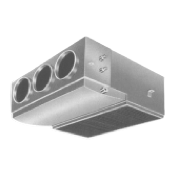
PARTS NAME Indoor unit Supply air grille Supply air chamber Outdoor unit Air inlet (Side and rear) Air outlet NOTE : Parts marked with the locally procured parts. Connecting duct Remote controller Pipes and electric wires indicate Indoor unit Duct flange Air filter Canvas Return air grille... -
Page 34: Parts Name Of Remote Controller
PARTS NAME OF REMOTE CONTROLLER Display section All display items are shown in right figure for the explanation. Only selected contents are displayed in actual operation. • When turning on the leakage breaker at the first time, [SET DATA] flashes on the display part of the remote controller. While this display is flashing, the model is being automatically confirmed. - Page 35 Operation section Push each button to select a desired operation. • The details of the operation needs to be set up once, the same states are used by pushing button. Fan mode button Selects a fan mode. Timer set button TIMER SET button is used when the timer is set up.
-
Page 36: Correct Usage
CORRECT USAGE When you use the air conditioner for the first time or when you change SET DATA value, follow the procedure below. From the next time, the operation will start as set state by pushing the Preparation Turn on the main power switch and/or the leakage breaker. •... -
Page 37: Automatic Operation (Auto Changeover)
AUTOMATIC OPERATION (Auto Changeover) When you set the air conditioner in either cooling, heating, or fan only operation depending on the indoor room temperature. Start button Push this button to start the air conditioner. Mode select button (MODE) Select Auto. Temperature button Set the desired temperature. - Page 38 TIMER OPERATION A type of timer operation can be selected from the following three types. OFF timer : The operation stops after the set time has passed. Repeat OFF timer : Every time, the operation stops after the set time has passed. ON timer : The operation starts after the set time has passed.
-
Page 39: Hints For Economical Operation
HINTS FOR ECONOMICAL OPERATION Maintain room temperature at comfortable level Clean air filters Airflow and performance are reduced if the air filters become blocked. Do not open doors and windows more often than necessary To keep cool or warm air in the room, do not open doors and windows more often than necessary. Window curtains In cooling, close the curtains to avoid direct sunlight. - Page 40 MAINTENANCE Cleaning of remote controller CAUTION • Use a dry cloth to wipe the remote controller. • A cloth dampened with cold water may be used on the indoor unit if it is very dirty. • Never use a damp cloth on the remote controller. •...
- Page 41 AIR CONDITIONER OPERATIONS AND PERFORMANCE 3 minutes protection function 3-minutes protection function prevents the air conditioner from starting for initial 3 minutes after the main power switch/circuit breaker is turned on for re-starting the air conditioner. Power failure Power failure during operation will stop the unit completely. •...
- Page 42 RE-INSTALLATION DANGER Ask the dealer or an installation professional to re-install the air conditioner to a new place or move it to another place and to observe the following items. If the air conditioner is inappropriate installed by yourself, it may cause electric shock or fire. Do not install the air conditioner in the following places •...
- Page 43 Before you ask for servicing or repairs, check the following points. Inoperative • The main power switch is turned off. • The circuit breaker is activated to cut off power supply. • The main power fuse has blown out. • Stoppage of electric current. Does not cool well or heat well •...
- Page 44 TROUBLES AND CAUSES (Concerning Remote Controller) Before you ask for servicing or repairs, check the following points: Symptoms The fan speed can not be • Check whether the MODE indi- changed. • Check whether the MODE indi- Setting Change is Impossible Causes cated on the display is “AUTO”.
-
Page 45: Accessory Parts And Parts To Be Procured Locally
Accessory parts and Parts to be procured locally r Accessory parts Part name Q’ty Pipe insulator 561BT Clamp for air 801BT filter fixing 1101BT 1401BT Washer for unit hung-up <Separate sold parts> Part name Q’ty Standard wired remote controller r Parts to be procured locally Connecting pipe (Liquid side) (6.4mm (diam.), Nominal (diam.) 1/4”... -
Page 46: Precautions For Safety
Accordingly the exclusive tools are required for the new refrigerant (R410A). For connecting pipes, use new and clean piping designed for R410A, and please care so that water or dust does not enter. Moreover, do not use the existing piping because there are problems with pressure-resistance force and impurity in it. - Page 47 • After unpacking the unit, examine it carefully if there are possible damage. • Do not install in a place that might increase the vibration of the unit. • To avoid personal injury (with sharp edges), be careful when handling parts. •...
-
Page 48: Selection Of Installation Place
SELECTION OF INSTALLATION PLACE • Install the air conditioner at enough strong place to withstand the weight of the unit. If the strength is not enough, the unit may fall down resulting in injury. • Install the air conditioner at a height 2.5m or more from the floor. If you insert your hands or others directly into the unit while the air conditioner operates, it is dangerous because you may contact with revolving fan or active electricity. -
Page 49: Installation Of Indoor Unit
INSTALLATION OF INDOOR UNIT Install the air conditioner certainly at a place to sufficiently withstand the weight. If the strength is insufficient, the unit may fall down resulting in human injury. Perform a specified installation work to guard against an earthquake. An incomplete installation can cause accidents by the units falling and dropping. -
Page 50: External View
INSTALLATION OF INDOOR UNIT External view The hanging bolt pitch on horizontal direction (B) is not halved at center with the ceiling opening size. Therefore, check the relational position in the following figure. Knock-out hole Ø125 (Air take-in port) 6-Ø4 Tapping screw undersized hole Ø160 Suction port canvas... - Page 51 1. Hanging down of indoor unit Refer to installation figures of hanging material and hanging bolt. • Adjustment of hanging bolt length and nut position Adjust hanging bolt length and nut position as shown in the figure before hanging down the indoor unit.
- Page 52 INSTALLATION OF INDOOR UNIT Concealed duct type NOTE: • Recommended supplying grille size 400 cm² each or more Ledge ceiling concealed duct type Quality of supplying grilles SM561BT SM801BT SM1101BT SM1401BT Restriction to installation 1. Installation clearance • As shown in the figure, keep clearance around the indoor unit. Inner ceiling 100mm or more Channel...
-
Page 53: Air Ducting Work
AIR DUCTING WORK Static pressure characteristics of each model Fig. 1 RAV-SM561BT (Round duct) Standard air volume 780m³/h Air volume m³/h Fig. 2 RAV-SM561BT (Square duct) Standard air volume 780m³/h Air volume m³/h Fig. 3 RAV-SM801BT (Round duct) Fig. 4 RAV-SM801BT (Square duct) Standard air volume 1140m³/h 1000 1140... - Page 54 AIR DUCTING WORK Fig. 5 RAV-SM1101BT (Round duct) Standard air volume 1620m³/h 1620 1200 Air volume m³/h Fig. 6 RAV-SM1101BT (Square duct) Standard air volume 1620m³/h 1620 1200 Air volume m³/h Fig. 7 RAV-SM1401BT (Round duct) 2000 1200 1800 Air volume m³/h Fig.
- Page 55 Installation reference The air supply ducting work is classified in two ways, one is branched by the round ducts, and the other is branched by the square ducts. (Be sure to divide the air supply duct into three or more branches.) <Round duct>...
- Page 56 AIR DUCTING WORK Connecting method of the duct 1. Supply air side <Round duct> 1. Make the round duct according to inner dimension of the flange Use a glass wool board with inside/outside finishing 25mm-thickness and 24kg/m³-density. 2. Connect the flange and each type of duct. (Fig. 1) Thermal insulator (50mm (w), 6mm (t)) Aluminum tape (50mm-width)
- Page 57 Hanging of indoor unit Lift up the unit with a lifter, etc., and set the hanging metal in the hanging bolt. • Hook nut of the hanging bolt to the groove of the hanging metal on the main unit. • Using the level, etc., install the main unit horizontally. Failure to do this will cause water leakage Mounting of filter and canvas for suction port 1.
-
Page 58: Drain Piping Work
DRAIN PIPING WORK Piping material • For laying pipes underground, use hard vinyl chloride pipe. VP25 (Inner diamater Ø32mm) Piping and cautions • Set drain side of pipe at downward slope. (1/100 or more) • Be sure to apply thermal insulation (foaming polyethylene, 10mm-thickness or more) for pipes passing through the room. - Page 59 Drain-up If down-slope cannot be set on a drain pipe, drain-up is possible. • Set the height of drain pipe 550mm or less from the bottom face of the indoor unit. • Pull out the drain pipe from connecting port of the drain pipe of the indoor unit by 100mm or shorter, and stand up it vertically.
-
Page 60: Refrigerant Piping
Outdoor unit is below 30 m Flaring Insert a flare nut into the pipe, and flare the pipe. As the flaring sizes of R410A differ from those of refrigerant R22, the flare tools newly manufactured for R410A are recommended. However, the conventional... -
Page 61: Evacuating
REQUIREMENT For a leak detector, use one manufactured exclusively for HFC refrigerant (R410A, R134a, etc.) Thermal-insulating process Perform pipe thermal-insulating process for liquid and gas sides separately. • For thermal insulator to pipes at gas side, use one with heat resisting temperature 120°C or higher. -
Page 62: Evacuating
EVACUATING <For 801, 1101, 1401AT model> • As shown in the figure, be sure to use a double spanner to loosen or tighten the flare nut of the valve at gas side. If using a single spanner, the nut cannot be tightened with necessary tightening torque. - Page 63 ELECTRICAL WORK NOTE: For selection and connection method of the power supply cords, refer to the details in the Installation Manual of the outdoor unit. • Be sure connect earth wire. Do not connect the earth wire to gas pipe, pipe of water supply, lightning conductor, and earth wire of telephone.
- Page 64 ELECTRICAL WORK Cabling 1. As shown in the figure, remove a screw then remove cover of the electric part. 2. Strip wire ends (10 mm). 3. Match wire colors with terminal numbers on indoor and outdoor units’ terminal blocks and firmly screw wires to the corresponding terminals.
-
Page 65: Test Run
TEST RUN Before test run • Before turning on the power supply, carry out the following procedure. 1) Using 500V-megger, check 1M or more exists between the terminal block 1 to 3 and the earth. If 1M or less is detected, do not run the unit. Do not apply to the remote controller circuit. 2) Check the valve of the outdoor unit being opened fully. -
Page 66: Troubleshooting
TROUBLESHOOTING Confirmation and check When a trouble occurred in the air conditioner, the check code and the indoor unit No. appear on the display part of the remote controller. The check code is only displayed during the operation. If the display disappears, operate the air conditioner according to the following “Confirmation of error history”... -
Page 67: Applicable Controls
APPLICABLE CONTROLS When using the equipment at the first time, it will take a lot of time that the remote controller accepts an operation after power was on. However, it is not a trouble. • Automatic address • While automatic addressing, the operation cannot be performed on the remote controller. •... - Page 68 APPLICABLE CONTROLS Setup of external static pressure Matching with the resistance (External static pressure) of the duct to be connected, be sure to set up the tap exchange according to the basic operation procedure • For the item code in Procedure •...
- Page 69 Change of lighting time of filter sign According to the installation condition, the lighting time of the filter sign (Notification of filter cleaning) can be changed. Follow to the basic operation procedure • For the item code in Procedure • For the set data in Procedure data of lighting time of filter sign to be changed from the table below.
-
Page 70: Installation/Servicing Tools
INSTALLATION/SERVICING TOOLS Tools Tools Applicable to R22 model Gauge manifold Charge hose ¡ Electronic balance for refrigerant charging Torque wrench (nominal diam. 1/4, 3/8, 1/2, 5/8) ¡ : Newly prepared (They are special requirements for R407C, separate from those for R22.) : Existing tools are available. - Page 71 WEEKLY TIMER FOR AIR CONDITIONER (SPLIT TYPE) <Program Weekly Timer Type> ... 72 RBC-EXW21E REMOTE CONTROLLER FOR AIR CONDITIONER <Simple Operation Type>... 78 RBC-AS21E Standard Remote Controller ... 81 RBC-AMT21E Simple Remote Controller ... 82 RBC-AS21E Program Weekly Timer ... 83 RBC-EXW21E Remote sensor ...
-
Page 72: Rbc-Exw21E
<Program Weekly Timer Type> RBC-EXW21E Thank you very much for purchasing TOSHIBA Weekly Timer for Air Conditioner. Please read this owner's manual carefully before using your Weekly Timer for Air Conditioner. • Be sure to obtain the “Owner’s manual” and “Installation manual” from constructor (or dealer). -
Page 73: Precautions For Safety
PRECAUTIONS FOR SAFETY WARNING WARNINGS ABOUT INSTALLATION • Make sure to ask the qualified installation professional in electric work to install the weekly timer for air conditioner. If the weekly timer for air conditioner is inappropriate installed by yourself, it may cause water leak, electric shock, fire, and so on. -
Page 74: How To Use The Timer Correctly
HOW TO USE THE TIMER CORRECTLY 1. Operation procedure Program weekly timer set up Power ON Setup of the present day of the week Turn on the power of the air conditioner. Setup of the program operation for a week 2. -
Page 75: Set Error
Set ON time by buttons, and then push button. When push button, the flashed ON time (8:00 in example) PROGRAM1 change, and OFF time of the PROGRAM2 program 1 flashes at the same PROGRAM3 time. WEEKLY TIMER PROGRAM PROGRAM1 HH MM PROGRAM2 PROGRAM3 Set OFF time by... -
Page 76: How To Copy The Program Operation Time
7. How to copy the program operation time When setting the program operation, already set program can be copied and set to the other day of the week. <Example: To copy the operation contents of Monday to Tuesday> 1. Push CHECK button in normal display. -
Page 77: Matters To Be Memorized
12. Matters to be memorized 1. Power failure When a power failure occurred and the power supply has been reset, the display of the right figure appears. (A colon “ ” flashes.) • Resuming of operation 1) Turn on the power (breaker) of the air condi- tioner. -
Page 78: Rbc-As21E
<Simple Operation Type> RBC-AS21E TThank you very much for purchasing TOSHIBA Remote Controller for Air Conditioner. Please read this owner's manual carefully before using your Remote Controller for Air Conditioner. • Be sure to obtain the “Owner’s manual” and “Installation manual” from constructor (or dealer). - Page 79 PRECAUTIONS FOR SAFETY WARNING WARNINGS ABOUT INSTALLATION • Make sure to ask the qualified installation professional in electric work to install the remote controller. If the remote controller is inappropriate installed by yourself, it may cause, electric shock, fire, and so on. WARNINGS ABOUT OPERATION •...
- Page 80 HOW TO OPERATE AIR CONDITIONER COOL/HEAT AUTO, HEAT, DRY, COOL, FAN Power supply Turn on the power supply of the air conditioner 12 hours before starting the operation. Push button. Push speed. When selecting AUTO, fan speed is automatically changed. (During FAN mode, the air speed is not.) Push either TEST...
-
Page 81: Rbc-Amt21E
INSTALLATION MANUAL Accessory parts NOTE 1 : Avoid to twist the remote controller cable with Part Name Q’ty Part Name Q’ty Remote controller Spacer NOTE 2 : Install the remote controller apart from the (200mm-cable attached) NOTE 3 : When noise is contained to the unit power Screw Wire joint M4 x 25... -
Page 82: Rbc-As21E
INSTALLATION MANUAL Accessory parts the remote controller switch Part Name Q’ty Part Name Q’ty Remote controller Spacer NOTE 1 : Avoid to twist the remote controller cable with the power supply cable, etc. or to store them in the Wire joint same metal pipe, otherwise it causes a malfunc- (200mm-cable attached) -
Page 83: Rbc-Exw21E
INSTALLATION MANUAL Accessory parts How to install the program weekly timer NOTE 1 : Q’ty Part Name Avoid to twist the program weekly timer cable with the power supply cable, etc. or to store Program weekly timer them in the same metal pipe, otherwise it causes a malfunction. -
Page 84: Tcb-Tc21Le
To Personnel Charged in Installation (Electric) Work and Service Accessory parts Part Name Q’ty Remote sensor Spacer (200mm-cable attached) Wire joint Small screw M4 x 25 Cable clamper Wood screw Installation Manual Requirement to install the remote sensor Installation place •... -
Page 85: Tcb-Fpc11Be/Tcb-Fpc21Be/Tcb-Fpc31Be/Tcb-Fpc41Be
Concealed Duct type Zeolite-3G Deodorant Filter Installation Manual Model: TCB-FPC11BE TCB-FPC21BE TCB-FPC31BE TCB-FPC41BE NOTES • Do not unpack the filter until you use it. (Otherwise, life of the Zeolite-3G deodorant filter is shortened.) • Keep this Manual with Owner’s Manual of the indoor unit. Safety Cautions •... -
Page 86: Safety Cautions
Concealed Duct type High-Efficiency Filter Installation Manual High-Efficiency filter (65%) Model: TCB-UFM11BE TCB-UFM21BE TCB-UFM31BE TCB-UFM41BE High-Efficiency filter (90%) Model: TCB-UFH51BE TCB-UFH61BE TCB-UFH71BE TCB-UFH81BE Safety Cautions • Before installation work, read thoroughly this “Safety Cautions” to install the air conditioner correctly. •... - Page 87 Concealed Duct type Deodorant Filter, Ammonium Filter Installation Manual Deodorant Filter Model: TCB-DF11BE TCB-DF21BE TCB-DF31BE TCB-DF41BE Ammonium Filter Model: TCB-DF11BE-AM TCB-DF21BE-AM TCB-DF31BE-AM TCB-DF41BE-AM Safety Cautions • Before installation work, read thoroughly this “Safety Cautions” to install the air conditioner correctly. •...