Table of Contents
Advertisement
Advertisement
Table of Contents

Related Manuals for Bosch NDP-7512-Z30C


Summary of Contents for Bosch NDP-7512-Z30C
- Page 1 AUTODOME IP starlight 7000i NDP‑7512‑Z30C │ NDP‑7512‑Z30CT Installation Manual...
-
Page 3: Table Of Contents
10.4 Fiber Optic Ethernet Media Converter (Optional) 10.5 Alarms and Relay Connections 10.6 Audio Connections (Optional) Troubleshooting 11.1 Rebooting the unit 11.2 Physical reset button 11.3 Customer Service and Support Maintenance Bosch Security Systems Installation Manual 2019-09 | 0.8 |... -
Page 4: Safety En
Legal Information Copyright This manual is the intellectual property of Bosch Security Systems, and is protected by copyright. All rights reserved. Trademarks All hardware and software product names used in this document are likely to be registered trademarks and must be treated accordingly. -
Page 5: Important Safety Instructions
For 24 VAC units, voltage applied to the unit's power input should not exceed ±10%, or 28 VAC. User-supplied wiring must comply with local electrical codes (Class 2 power levels). Do not ground the supply at the terminals or at the unit's power supply terminals. Bosch Security Systems Installation Manual 2019-09 | 0.8 |... - Page 6 16. Attachments, changes or modifications - Only use attachments/accessories specified by the manufacturer. Any change or modification of the equipment, not expressly approved by Bosch, could void the warranty or, in the case of an authorization agreement, authority to operate the equipment.
- Page 7 Electrical Code ® (NEC)), Canadian Electrical Code, Part I (also called CE Code or CSA C22.1), and all applicable local codes. Bosch Security Systems accepts no liability for any damages or losses caused by incorrect or improper installation. Warning! INSTALL EXTERNAL INTERCONNECTING CABLES IN ACCORDANCE TO NEC, ANSI/NFPA70 (FOR US APPLICATION) AND CANADIAN ELECTRICAL CODE, PART I, CSA C22.1 (FOR CAN...
-
Page 8: Important Notices
Camera signal - Protect the cable with a primary protector if the camera signal is beyond 140 feet, in accordance with NEC800 (CEC Section 60). Environmental statement - Bosch has a strong commitment towards the environment. This device has been designed to respect the environment as much as possible. - Page 9 Ce produit est un appareil de Classe A. Son utilisation dans une zone résidentielle risque de provoquer des interférences. Le cas échéant, l’utilisateur devra prendre les mesures nécessaires pour y remédier. Bosch Security Systems Installation Manual 2019-09 | 0.8 |...
- Page 10 Any such modifications could void the user's authority to operate the equipment. If necessary, the user should consult the dealer or an experienced radio/television technician for corrective action. 2019-09 | 0.8 | Installation Manual Bosch Security Systems...
-
Page 11: Connection In Applications
High Power-over-Ethernet (High PoE): This unit can by powered via High PoE. To power the unit this way, use only approved High PoE devices - those offered or recommended by Bosch. High PoE can be connected at the same time as a 24 VAC power supply. If auxiliary power (24 VAC to camera and to heater) and High PoE are applied simultaneously, the camera will selects auxiliary input (24 VAC) as the primary power source. -
Page 12: Customer Support And Service
| Safety EN AUTODOME IP starlight 7000i Customer Support and Service If this unit needs service, contact the nearest Bosch Security Systems Service Center for authorization to return and shipping instructions. Telephone: 800-366-2283 Fax: 800-366-1329 Email: cctv.repair@us.bosch.com Customer Service... -
Page 13: Unpacking
Verify that all the parts listed in the Parts List below are included. If any items are missing, notify your Bosch Security Systems Sales or Customer Service Representative. – Do not use this product if any component appears to be damaged. Please contact Bosch Security Systems in the event of damaged goods. –... -
Page 14: Tools Required
Appropriate tool for In-ceiling Mount cutting a hole in drywall or ceiling tile Pliers In-ceiling Mount The following table lists additional products, sold separately by Bosch or other manufacturers, necessary to install AUTODOME cameras. Quantity Product Part Number Size SD card... -
Page 15: Product Description
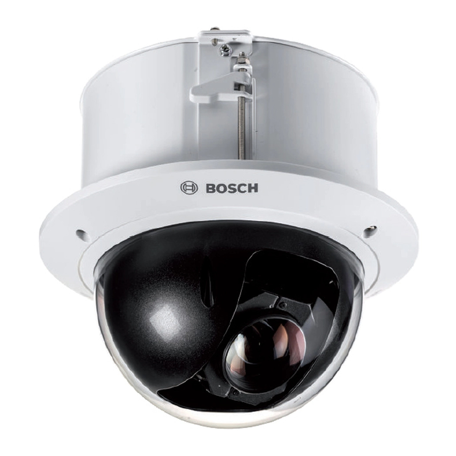
(HD) 1080p video. Easy to install, the camera is available in either a field-proven, outdoor pendant housing or an indoor, in-ceiling housing. The camera has been designed for quick and easy installation, a key feature from Bosch IP video security products. -
Page 16: Preparing The Bubble
Notice! To avoid excessive moisture saturation inside the housing, limit the amount of time that the bubble is disconnected from the housing. Bosch recommends that the bubble be removed from the housing for no more than five (5) minutes. Remove the bubble from an in-ceiling housing Loosen the lockscrew (item 1 in the illustration below) in the trim ring using a P1 or smaller Phillips screwdriver until the bubble can rotate freely. -
Page 17: Optional) Installing An Sd Card
Follow the steps in one of these sections (depending on the type of camera mount): Replace the bubble in an in-ceiling housing or Replace the bubble in a pendant housing. Bosch Security Systems Installation Manual 2019-09 | 0.8 |... -
Page 18: Replacing The Trim Ring And Bubble
Forcing the screw into the trim ring (without the screw going into the screw slot in the housing) can deform the ring. Erase the chalk or pencil mark if desired. 2019-09 | 0.8 | Installation Manual Bosch Security Systems... -
Page 19: Installing The In-Ceiling Mount
Place the Bracket Assembly over the ceiling tile, which is used to mount the camera. Snap the Bar Clips of the bracket to the ceiling rails. Bosch Security Systems Installation Manual 2019-09 | 0.8 |... -
Page 20: Wire The Interface Box
Wire the Interface Box The Interface Box can be wired through the top or side. Use the supplied rubber plug to seal the hole which will not be used to route wires. 2019-09 | 0.8 | Installation Manual Bosch Security Systems... - Page 21 Connect the plugs to their mating connectors P103 and P102 in the Interface Box. Connector Label Description Wire Color Alarm Out Connector [P102] OUT1 Alarm Out 1 White OUT2 Alarm Out 2 Brown OUT3 Alarm Out 3 Orange AGND Alarm ground Green Bosch Security Systems Installation Manual 2019-09 | 0.8 |...
-
Page 22: Interface Box Connections
Secure the lid to the Interface box by pushing the lid down until the clip on the lid catches against the box. Interface Box Connections The following figure is a detailed illustration of the In-ceiling Interface box. 2019-09 | 0.8 | Installation Manual Bosch Security Systems... -
Page 23: Installing The Ceiling (Ip54 Housing) Gasket
In addition, if you are using the optional black trim ring instead of the factory-installed white trim ring, the trim ring gasket must also be in place to provide the IP54 protection. (Refer to Replace the trim ring (optional) (In-ceiling models) for step-by-step installation instructions.) Bosch Security Systems Installation Manual 2019-09 | 0.8 |... -
Page 24: Attach Housing To The Interface Box
Carefully slide the gasket down over the housing, until it rests on the flange of the housing. Attach Housing to the Interface Box The In-Ceiling Housing is attached to the Interface Box and secured by two (2) thumbscrews. 2019-09 | 0.8 | Installation Manual Bosch Security Systems... - Page 25 The In-ceiling dome is provided with tether points on each side of the housing. To prevent injury, attach a safety wire from a secure anchor point above the ceiling to a tether point on the dome housing. See below for an illustration. Bosch Security Systems Installation Manual 2019-09 | 0.8 |...
-
Page 26: Secure Housing To Ceiling
40 mm 1.57 in. MAXIMUM CEILING 6.5 mm 0.26 in. MINIMUM CEILING inches Figure 7.7: Secure camera to ceiling Tether Point Ceiling Clamp Ceiling Clamp Rotate Clockwise to Engage Clamp Tether Point 2019-09 | 0.8 | Installation Manual Bosch Security Systems... - Page 27 Over-torquing the Ceiling Clamps can damage the clamp or ceiling. Only tighten the clamp until it contacts the ceiling and you start to feel some resistance. If using a power screwdriver, set the torque level to the lowest setting. Bosch Security Systems Installation Manual 2019-09 | 0.8 |...
-
Page 28: Finalizing Installation
| Finalizing installation AUTODOME IP starlight 7000i Finalizing installation Remove the plastic on the bubble After you complete all other installation steps, remove the plastic material that is protection for the bubble. 2019-09 | 0.8 | Installation Manual Bosch Security Systems... -
Page 29: Replacing An In-Ceiling Hd Acrylic Bubble
Forcing the screw into the trim ring (without the screw going into the screw slot in the housing) can deform the ring. Bosch Security Systems Installation Manual 2019-09 | 0.8 |... -
Page 30: Connection
IP Connection Network Switch Computer Notice! You can also use the Bosch Video Client software application to configure the network settings for an AUTODOME 7000 Series camera. Go to www.boschsecurity.com to download the Configuration Manager software and Operating Manual. 10.2... -
Page 31: Ethernet Connections
IP network using the built-in Web server. In addition, power can be supplied over the Ethernet cable using the Bosch High PoE 60W midspan (sold separately). Power can also be supplied over the Ethernet cable to in-ceiling models and indoor/outdoor pendant models used in indoor applications (where the heater is not powered) using PoE+ PSEs (midspan switches) compliant with the IEEE 802.3at, class 4 standard. -
Page 32: Fiber Optic Ethernet Media Converter (Optional)
100 m (328 ft) Bandwidth 10 Base-T/100 Base-TX High PoE (required for pendants in outdoor applications that use Use the Bosch High PoE 60W midspan heaters) (sold separately). PoE+ (only for indoor models or indoor applications for pendant model IEEE 802.3at, class 4 standard... -
Page 33: Alarms And Relay Connections
Alarm 1 or 2 only (Pin 5 or 6) Ground (Pin 7) From Configuration, select Interfaces > Alarm Inputs, select the number of the Alarm input and finally, select N.O. See the table below for contact and condition details. Bosch Security Systems Installation Manual 2019-09 | 0.8 |... - Page 34 Configuring a Normally Open Non-supervised Alarm Connect the alarm to the appropriate input (3 through 7) and ground at the camera. Figure 10.4: N.O. - Normally Open Non-supervised Connections Dry Contact Dome Connector 2019-09 | 0.8 | Installation Manual Bosch Security Systems...
- Page 35 5 and 32 V to complete the circuit, with a maximum voltage rating of 32 VDC @ 150 ma. Connect the appropriate stripped wire to the open connector (1, 2, or 3) of the transistor. Connect the appropriate stripped wire to the ground (GND) connector. Bosch Security Systems Installation Manual 2019-09 | 0.8 |...
-
Page 36: Audio Connections (Optional)
Remove the 100 Ohm termination resistor from the C+ to C- terminals. Connect the audio line level source to the Audio_In+ (C+) input terminal. Connect the audio signal ground to the Audio_In- (C-) input terminal. 2019-09 | 0.8 | Installation Manual Bosch Security Systems... - Page 37 Audio_Out+ (RXD) Audio_Out– (TXD) Signal Ground Notice! Separate the audio cables from the AC power lines to avoid noise. To configure audio on the camera, refer to Basic Mode: Audio or Audio. Bosch Security Systems Installation Manual 2019-09 | 0.8 |...
-
Page 38: Troubleshooting
If you cannot control the unit after the firmware upgrade, then cycle the power to the unit. If a power reset does not solve the problem, or if Configuration or video management software identifies the unit as “Videojet Generic,” then contact your Bosch Service Center for an RMA for the unit. -
Page 39: Physical Reset Button
Let the camera complete a self-check. When the self-check completes, the red LED will go off. Find the IP address again. Access the camera using the web browser. Set the initial service-level password for the camera. Bosch Security Systems Installation Manual 2019-09 | 0.8 |... - Page 40 | Troubleshooting AUTODOME IP starlight 7000i 2019-09 | 0.8 | Installation Manual Bosch Security Systems...
-
Page 41: Customer Service And Support
AUTODOME IP starlight 7000i Troubleshooting | en 11.3 Customer Service and Support If this unit needs service, contact the nearest Bosch Security Systems Service Center for authorization to return and shipping instructions. Telephone: 800-366-2283 Fax: 800-366-1329 Email: cctv.repair@us.bosch.com Customer Service... -
Page 42: Maintenance
Dry the bubble thoroughly with a dry nonabrasive cloth to prevent water spots. Never scrub the bubble with any abrasive material or cleaners. Bosch recommends cleaning the exterior of the bubble with NOVUS “No. 1” Plastic Clean & Shine (or equivalent), according to manufacturer’s instructions. Refer to www.novuspolish.com to order or to find a local distributor. - Page 43 AUTODOME IP starlight 7000i Maintenance | Bosch Security Systems Installation Manual 2019-09 | 0.8 |...
- Page 44 | Maintenance AUTODOME IP starlight 7000i 2019-09 | 0.8 | Installation Manual Bosch Security Systems...
- Page 46 Bosch Sicherheitssysteme GmbH Bosch Security Systems, Inc Robert-Bosch-Ring 5 1706 Hempstead Road 85630 Grasbrunn Lancaster, PA, 17601 Germany www.boschsecurity.com © Bosch Sicherheitssysteme GmbH, 2019...