Bosch MIC IP starlight 7000i Installation Manual
Hide thumbs
Also See for MIC IP starlight 7000i:
- User manual (86 pages) ,
- Installation manual (72 pages) ,
- Tech note (20 pages)
Table of Contents
Advertisement
Advertisement
Table of Contents

Related Manuals for Bosch MIC IP starlight 7000i


Summary of Contents for Bosch MIC IP starlight 7000i
- Page 1 MIC IP starlight 7000i Installation Manual...
-
Page 3: Table Of Contents
MIC IP starlight 7000i Table of contents | en Table of contents Safety About this Manual Legal Information Safety Precautions Important Safety Instructions Important Notices Important Notices - Illumination Safety Customer Support and Service Introduction Configuration with Project Assistant app... -
Page 4: Safety
Legal Information Copyright This manual is the intellectual property of Bosch Security Systems, and is protected by copyright. All rights reserved. Trademarks All hardware and software product names used in this document are likely to be registered trademarks and must be treated accordingly. -
Page 5: Safety Precautions
MIC IP starlight 7000i Safety | en Safety Precautions In this manual, the following symbols and notations are used to draw attention to special situations: Danger! High risk: This symbol indicates an imminently hazardous situation such as “Dangerous Voltage” inside the product. If not avoided, this will result in an electrical shock, serious bodily injury, or death. -
Page 6: Important Safety Instructions
– Do not point the camera at the sun. Bosch Security Systems will not be liable for any damage to cameras that have been pointed directly at the sun. 2019-11 | 2.1 |... - Page 7 Notice! Bosch recommends the use of surge/lightning protection devices (sourced locally) to protect network and power cables and the camera installation site. Refer to NFPA 780, Class 1 & 2, UL96A, or the equivalent code appropriate for your country/region, and to local building codes.
-
Page 8: Important Notices
| Safety MIC IP starlight 7000i Important Notices For use in China: CHINA ROHS DISCLOSURE TABLE Moving cameras Hazardous substance table according to SJ/T 11364-2014 Cr 6+ PBDE (Pb) (Hg) (Cd) (Cr 6+) (PBB) (PBDE) Housing & enclosures PCBA with connectors... - Page 9 MIC IP starlight 7000i Safety | en Environmental statement - Bosch has a strong commitment towards the environment. This device has been designed to respect the environment as much as possible. Electrostatic-sensitive device - Use proper ESD safety precautions when handling the camera to avoid electrostatic discharge.
- Page 10 | Safety MIC IP starlight 7000i Note: Changes or modifications not expressly approved by Bosch could void the user’s authority to operate the equipment. FCC & ICES Information (U.S.A. and Canadian Models Only) This device complies with part 15 of the FCC Rules. Operation is subject to the following conditions: –...
-
Page 11: Important Notices - Illumination Safety
MIC IP starlight 7000i Safety | en Important Notices - Illumination Safety The text in this section applies only to cameras which have the optional illuminator accessory. The IEC 62471 provides the methods to determine the risk group of any lamp or any product incorporating a lamp. -
Page 12: Customer Support And Service
| Safety MIC IP starlight 7000i Customer Support and Service If this unit needs service, contact the nearest Bosch Security Systems Service Center for authorization to return and shipping instructions. Telephone: 800-366-2283 Fax: 800-366-1329 Email: cctv.repair@us.bosch.com Customer Service Telephone: 888-289-0096 Fax: 585-223-9180 Email: security.sales@us.bosch.com... -
Page 13: Introduction
You can also use the Project Assistant app to complete the initial configuration of the camera. In order to use this device with the Project Assistant app by Bosch, you must download the app from the Bosch Download Store, from Google Play, or from the Apple Store. -
Page 14: Product Description
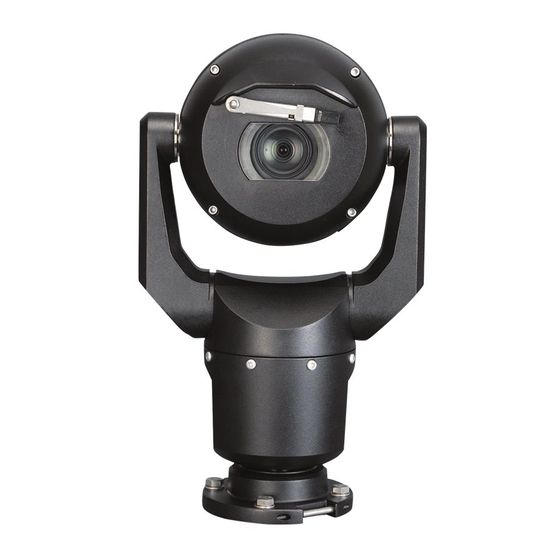
Make sure that the installation conditions comply with the specified stresses of vibration and shock as mentioned in the datasheet. The MIC IP starlight 7000i camera is an advanced PTZ surveillance platform for mission-critical applications. With starlight imaging technology and excellent low-light sensitivity, the MIC IP starlight 7000i camera is the perfect solution for robust and high-quality imaging needs. - Page 15 MIC IP starlight 7000i Product Description | en - MIC-ILB-300 Black - MIC-ILW-300 White - MIC-ILG-300 Grey Bosch Security Systems Installation Manual 2019-11 | 2.1 |...
-
Page 16: Overview Of Installation Steps
Electrical Code ® (NEC)), Canadian Electrical Code, Part I (also called CE Code or CSA C22.1), and all applicable local codes. Bosch Security Systems accepts no liability for any damages or losses caused by incorrect or improper installation. Caution! ELECTRIC SHOCK HAZARD... -
Page 17: Mounting
MIC IP starlight 7000i Mounting | en Mounting Mounting Location and Orientation Options MIC cameras are designed for easy installation in various locations such as directly onto buildings and poles suitable to support CCTV equipment. Select a secure installation location and mounting orientation for the device. Ideally, this is a location where the device cannot be interfered with either intentionally or accidentally. -
Page 18: Mounting Options
If the camera is installed in a highly exposed location where lightning strikes may occur, then Bosch recommends installing a separate lightning conductor within 0.5 m (1.6 ft) of the camera and at least 1.5 m (4.9 ft) higher than the camera. A good earth bonding connection to the camera housing itself will provide protection against damage from secondary strikes. - Page 19 MIC IP starlight 7000i Mounting | en Figure 5.1: Top view of canted MIC7000 illustrating distance of pan clearance The figure below illustrates the tilt range of the camera in upright orientation. 90° 90° 55° 55° Figure 5.2: MIC7000 Tilt Range: 145° each direction; 290° if AutoPivot enabled...
-
Page 20: Mounting Bracket Options
Bosch sells a complete series of mounting brackets that support multiple mounting configurations. Always use only Bosch-supplied mounts, which are designed for safe installation of your MIC camera. Refer to the MIC Series Mounting Brackets Installation Guide for complete installation instructions. - Page 21 MIC IP starlight 7000i Mounting | en Pole Mount The figure below identifies the three mounting accessories (each sold separately) that are necessary to mount the MIC camera on the side of a pole. Note: The figure identifies the part numbers, as well as the codes for the available colors (-BD for black, -WD for white, and -MG for grey) of each mounting accessory.
-
Page 22: Considerations For Mounting The Camera In Inverted Orientation
| Mounting MIC IP starlight 7000i Route cables through the bottom of the SCA (to prevent water from running into the side or top of the SCA along the cables). Surface Mount Figure 5.6: Direct surface mount – camera upright (MIC + base gasket) Figure 5.7: Direct surface mount –... - Page 23 MIC IP starlight 7000i Mounting | en Figure 5.8: MIC camera with camera head inverted Note: It is not necessary to remove the section for the illuminator on the sunshield because the illuminator is attached to the opposite side of the camera visor.
-
Page 24: (Optional) Configuration Programming In The Shipping Box
| (Optional) Configuration Programming in the Shipping Box MIC IP starlight 7000i (Optional) Configuration Programming in the Shipping The camera packaging allows installers to connect the camera to the network and configure the camera still in the box. Caution! Risk of damage to camera Do not change the camera orientation to “Inverted”... -
Page 25: Optional) Configuration Programming On A Temporary Table-Top Stand
MIC IP starlight 7000i (Optional) Configuration Programming on a Temporary Table-top Stand | en (Optional) Configuration Programming on a Temporary Table-top Stand Caution! Take extra care lifting or moving MIC cameras because of their weight. The camera (still in the foam) can stand temporarily on a flat, horizontal surface such as a desk or a table during initial network connection and configuration. -
Page 26: (Optional) Installing The Illuminator
| (Optional) Installing the Illuminator MIC IP starlight 7000i (Optional) Installing the Illuminator Use the correct set of tools as well as the recommended torque values given in the instructions that follow. The use of the wrong tools or torque values may cause damage to threads or seal caps, which may result in leaks or damage to paint, which then may lead to the start of corrosion. - Page 27 MIC IP starlight 7000i (Optional) Installing the Illuminator | en From the web browser, access the camera’s Settings page. Select Advanced > Camera > Installer Menu > Orientation, and then select “Inverted”. Click Set to confirm the selection. The camera head will rotate automatically into inverted position (180°).
- Page 28 | (Optional) Installing the Illuminator MIC IP starlight 7000i 2. Remove and discard the three (3) plastic screws surrounding the appropriate access port where the illuminator will be installed. 3. Remove the appropriate access plug from the camera head with the supplied spanner wrench.
- Page 29 MIC IP starlight 7000i (Optional) Installing the Illuminator | en Bosch suggests storing the access plug inside the DCA mount (or wall mount accessory) in case it becomes necessary to remove the illuminator. 4. Remove the plastic cap from the illuminator accessory. Discard.
- Page 30 | (Optional) Installing the Illuminator MIC IP starlight 7000i 5. Align the illuminator over the access port and carefully push into position on the camera head. 0 - 0.7 N m 0.7 - 1.4 N m 1.4 N m 6.
- Page 31 MIC IP starlight 7000i (Optional) Installing the Illuminator | en 7. Remove the translucent film. Bosch Security Systems Installation Manual 2019-11 | 2.1 |...
- Page 32 | (Optional) Installing the Illuminator MIC IP starlight 7000i 287.93 mm (11.34 in.) 8. Installation of the illuminator is complete. 2019-11 | 2.1 | Installation Manual Bosch Security Systems...
-
Page 33: Optional) Canting The Camera
The graphics do not depict other accessories that you may have installed already. MIC7000 / MIC IP starlight 7000i cameras have on-site canting functionality. Installers can adjust the camera from an upright position to a canted position (45º angle) if necessary. - Page 34 Bosch strongly recommends attaching the camera to a DCA and mounting the DCA before canting the camera. To cant the camera, follow these steps: 1.
- Page 35 MIC IP starlight 7000i (Optional) Canting the Camera | en Notice! Risk of damage to the device. Without the yoke arm screws in position, the camera head can fall and be damaged. Hold the head of the camera as you complete the next four (4) steps.
- Page 36 | (Optional) Canting the Camera MIC IP starlight 7000i Torque requirements for yoke arm screws SN ≥ xxxxxxx46029xxxxxx (> Dec. 2014) 5 mm Hex (T30 Torx) ≈ 7.5 N m (≈ 5.5 ft lb) ≈ 17 N m (≈ 12.5 ft lb) ≈...
- Page 37 MIC IP starlight 7000i (Optional) Canting the Camera | en 11. Change the camera orientation to “Canted.” Complete the following steps: – Access the page Configuration. – Navigate to Camera > Installer Menu > Orientation. – Select “Canted.” Bosch Security Systems Installation Manual 2019-11 | 2.1 |...
-
Page 38: Replacing A Wiper Assembly
| Replacing a wiper assembly MIC IP starlight 7000i Replacing a wiper assembly Put a piece of thin, protective material between the window glass and the wiper to prevent accidental damage. 2019-11 | 2.1 | Installation Manual Bosch Security Systems... - Page 39 MIC IP starlight 7000i Replacing a wiper assembly | en With one hand, hold the wiper arm firmly in place to restrict rotational movement. With the other hand, using a 7mm Hex socket or nut driver, rotate the acorn nut counter- clockwise until the nut is free from the wiper shaft.
- Page 40 | Replacing a wiper assembly MIC IP starlight 7000i Remove the wiper spring, hub, arm, and blade assembly from the wiper shaft. Assemble the new wiper arm on the new wiper hub. 2019-11 | 2.1 | Installation Manual Bosch Security Systems...
- Page 41 MIC IP starlight 7000i Replacing a wiper assembly | en Insert the new blade assembly into the new wiper arm. Slide the new wiper hub and the attached parts onto the wiper shaft. Bosch Security Systems Installation Manual 2019-11 | 2.1 |...
- Page 42 | Replacing a wiper assembly MIC IP starlight 7000i Slide the new wiper spring onto the wiper shaft and over the new wiper arm. 2019-11 | 2.1 | Installation Manual Bosch Security Systems...
- Page 43 MIC IP starlight 7000i Replacing a wiper assembly | en Apply Loctite 243 to the cavity of the acorn nut. 10. Lightly thread the new acorn nut onto the wiper shaft over the new wiper spring and new wiper hub.
- Page 44 | Replacing a wiper assembly MIC IP starlight 7000i 11. With one hand, hold the new wiper arm firmly in place to restrict rotational movement and to keep the wiper assembly parallel with the flat top of the glass.
-
Page 45: Connections
24 VAC. After the High PoE Midspan power source is restored, the camera switches power input again to the High PoE Midspan. Bosch recommends 24VAC power output of 24V at 100VA, 4A with a slow blow fuse. The power supply must be certified to UL/IEC 60950-1 2nd Edition, AM1+AM2 or UL/IEC 62368-1 2nd Ed, Output 24 VAC, LPS, +65 °C (+149 °F) min. -
Page 46: Ethernet Connections
For models with attached illuminators: Use the 95 W midspan sold by Bosch. For models without illuminators: Use the 60 W midspan sold by Bosch, or a midspan that is compliant to the IEEE 802.3at, class 4 standard. Note: Consult the National Electrical Code (NEC) or other regional standards for cable bundling requirements and limitations. -
Page 47: Connect The Camera To The Network
Note: If the MIC camera will be installed directly to a mounting surface, instead of onto a MIC DCA or a MIC wall mount bracket, Bosch recommends using the connector kit for your model of camera to protect the connections against moisture and dust particles. Each kit provides components for connecting as many as 5 MIC cameras. - Page 48 | Connections MIC IP starlight 7000i – If using a High PoE midspan power source: a. Connect one end of a Cat5e/Cat6 Shielded Twisted Pair (STP) Ethernet cable to the RJ45 connector of the camera. b. Connect the other end of the cable to the DATA + POWER OUT port on the midspan.
-
Page 49: Typical System Configurations
MIC IP starlight 7000i Typical System Configurations | en Typical System Configurations 12.1 Typical IP Configuration with High PoE midspan (no I/O connections) Figure 12.1: Typical IP configuration with High PoE Midspan (no I/O connections) 1 MIC camera 2 MIC Hinged DCA (MIC-DCA-Hx) -
Page 50: Typical Configuration With Mic-Alm-Was-24
| Typical System Configurations MIC IP starlight 7000i 12.2 Typical Configuration with MIC-ALM-WAS-24 Figure 12.2: Typical configuration with MIC-ALM-WAS-24 1 MIC7000 camera 6 24 VAC Power pack, 1A, 50/60 Hz (user- supplied) 2 MIC Hinged DCA (MIC-DCA-Hx) 7 Washer pump accessory... -
Page 51: Typical Ip Configuration With Vjc-7000-90
Figure 12.3: Basic configuration with VIDEOJET connect 7000 1 Ethernet (network) cable (Cat5e/Cat6 Shielded Twisted Pair (STP)) (user-supplied) between a Bosch camera and the port labeled PoE on VIDEOJET connect 7000 2 Data-only IP cable (Cat5e/Cat6 Shielded Twisted Pair (STP)) to the head-end network Note: The cable to the head-end also can be fiber optic cable from one of the two SFP slots. -
Page 52: Troubleshooting
Camera reboots frequently or Your camera has an improper network connection. intermittently Test your camera with another power supply. Check the Bosch website for a software update that might address the issue. No OSD messages appear. Bosch’s Video SDK is required. Video management software from third parties does not use the SDK. -
Page 53: Maintenance
No User-serviceable Parts Except for the external wiper blade, the device contains no user-serviceable parts. Contact your local Bosch service center for device maintenance and repair. In the event of failure, the device should be removed from site for repair. -
Page 54: Disposal
MIC IP starlight 7000i Disposal Disposal Your Bosch product has been developed and manufactured using high- quality materials and components that can be reused. This symbol means that electronic and electrical devices that have reached the end of their working life must be disposed of separately from household waste. -
Page 55: Technical Data
MIC IP starlight 7000i Technical data | en Technical data For product specifications, see the datasheet for your camera, available on the appropriate product pages of the Online Product Catalog at www.boschsecurity.com. Bosch Security Systems Installation Manual 2019-11 | 2.1 |... -
Page 56: Best Practices For Outdoor Installation
| Best Practices for Outdoor Installation MIC IP starlight 7000i Best Practices for Outdoor Installation Cameras installed outdoors are susceptible to surges and lightning. Always include surge and lightning protection when installing outdoor cameras. The following figure is an illustration of the proper configuration for installing IP PTZ cameras (AUTODOME and MIC) outdoors with surge and lightning protection. - Page 57 MIC IP starlight 7000i Best Practices for Outdoor Installation | en 1 Indoor main building 2 Network equipment 3 Connect the ground of the camera 4 Surge protection power supply to the building earth ground. 5 Connect the ground of the camera to 6 Install Cat5e/Cat6 (Shielded Twisted the ground of the surge protector.
-
Page 58: Error Codes
| Error Codes MIC IP starlight 7000i Error Codes For certain conditions, MIC cameras will display status codes on the video image. The table below identifies the status codes, their descriptions, and the recommended action to resolve the condition. - Page 59 2. Verify the integrity/tightness of the external fasteners. Tighten where necessary. 3. If obvious damage is present, stop using the camera and contact the nearest Bosch Security Systems Service Center. 4. If no damage is evident, power the camera off and then on, and then evaluate operational performance.
- Page 60 | Error Codes MIC IP starlight 7000i Status Description Recommended action Code (to be completed by a qualified Service Technician) Wiper operation has been halted 1. Remove any obvious materials that are because of an obstruction. obstructing operation of the wiper.
- Page 61 (and the window defrosters, for MIC IP fusion 9000i). If the log notes heater or defroster failure, contact the nearest Bosch Security Systems Service Center. 3. If operation is obstructed because of...
- Page 62 | Error Codes MIC IP starlight 7000i If this action does not resolve the problem, contact the nearest Bosch Security Systems Service Center. The Service Center may request information from the diagnostics log of the camera (accessible from the Service menu).
- Page 63 MIC IP starlight 7000i Error Codes | Bosch Security Systems Installation Manual 2019-11 | 2.1 |...
- Page 64 | Error Codes MIC IP starlight 7000i 2019-11 | 2.1 | Installation Manual Bosch Security Systems...
- Page 66 Bosch Security Systems B.V. Torenallee 49 5617 BA Eindhoven Netherlands www.boschsecurity.com © Bosch Security Systems B.V., 2019...