SMC Networks EX500 Series Instruction Manual
Reduced wiring system cc-link compatible gw unit
Hide thumbs
Also See for EX500 Series:
- Technical instruction manual (40 pages) ,
- Instruction manual (22 pages)

Related Manuals for SMC Networks EX500 Series


Summary of Contents for SMC Networks EX500 Series
- Page 1 Reduced wiring system CC-Link Compatible GW Unit Instruction Manual EX500-GMJ1 URL http://www.smcworld.com EX##-OMI0026...
-
Page 2: Table Of Contents
Contents Thank you for purchasing the SMC reduced wiring system EX500 series. SAFETY ......................2 Product Summary....................5 Please read this instruction manual carefully and understand the contents before EX500 use so that you can operate this unit safely and correctly. Part Names ....................6 Please keep this manual handy for future reference. -
Page 3: Safety
SAFETY The body of unit and this manual contain the essential information for the protection of users and others from possible injury and property damage and to ensure correct handling. Before performing maintenance: Turn off power supply. Please check that you fully understand the definitions of the following messages Stop air supply, exhaust compressed air in piping, and confirm the release to ( symbols ) before going on to read the body of this manual, and always follow the atmosphere. -
Page 4: Product Summary
Product Summary SAFETY ( continued ) Follow the instructions given below when handling your reduced wiring system. System configuration Otherwise a damage or failure to cause a malfunction can result. Operate the reduced wiring system at the specified voltage. BUS adapter Reserve space for maintenance. -
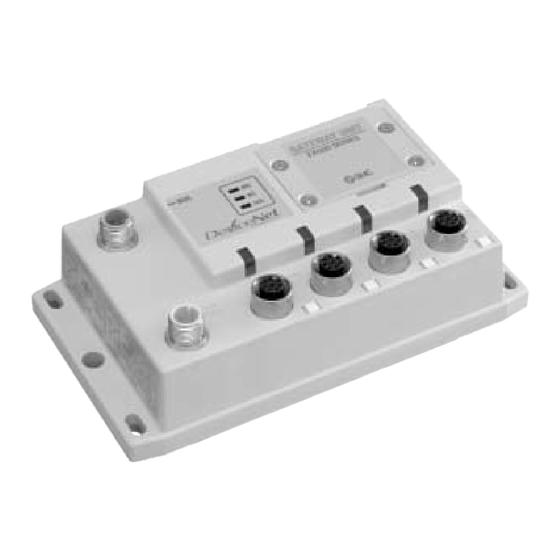
Page 5: Ex500 Part Names
EX500 Part Names Dimensions ( unit: mm ) EX500 body Accessory Name Application Bus adapter ( accessory ) Communication Connect with CC-Link line by using the accessory 18.5 connector bus adapter . ( Note1 ) Power supply connector Supply power for output devices such as solenoid unit side valve, for input devices such as sensor, and for controlling GW/SI by using power supply connector... -
Page 6: Specification
Specification Wiring Basic specifications Internal circuit Rated voltage DC24V Range of power Power supply for input and controlling GW/SI: DC24V 10% RD - supply voltage Power supply for output: DC24V+10%/-5% ( Voltage drop TD - warning at around 20V ) adapter COM A +24V... - Page 7 Wiring ( continued ) Pin layout and connection diagram of cable with CC-Link communication connectors Communication wiring Connect the communication cable with socket-type M12 connector on IN side and plug- type M12 connector on OUT side. For cable to be used, refer to "Appendix Table" ( page 41 ) in this manual. Avoid the mixing of CC-Link dedicated high-performance cable and other cables ( CC-Link dedicated cable and/or Version 1.10 compatible CC-Link dedicated cable ).
- Page 8 Wiring ( continued ) Connection of terminal resistor Power supply wiring Connect the power supply connector cable to the power supply connector of GW unit. To the units at both ends of CC-Link system, be sure to connect terminal resistors. There are two types of cables different in connector shape ---- straight type and angle Connect the terminal resistor between "DA"...
- Page 9 Wiring ( continued ) Separate wiring for power supply for solenoid valves/output and for input Branch wiring ( wiring to communication ports ) and control of GW/SI For wiring with solenoid valves or input devices, connect the branch cable with M12 connector to communication ports A - D.
- Page 10 Wiring (continued ) For GW unit – Manifold valve – Input unit manifold configuration For GW unit – Input unit manifold configuration Two communication connectors in SI unit and one communication connector in Input To the communication connector of Input unit, connect the branch cable with M12 unit are installed respectively.
-
Page 11: Display/Switch Setting
Display/Switch Setting Settings for display Switch setting Open the station number switch protective cover and set the switches with a fine-pointed watchmakers screwdriver etc. NOTE 1. Be sure to turn off the power before setting the switches. 2. Be sure to set these switches before use. The factory default settings are all "OFF"... -
Page 12: Si Unit Part Names
SI Unit Part Names Display/Switch Setting ( continued ) Transmission speed and HOLD/CLR setting ( SW3 ) The SI unit is the unit to communicate with GW unit in combination with manifold valve. It can be used with SV series valves and VQC series valves. Set transmission speed and HOLD/CLR by SW3 as shown below. -
Page 13: Mounting/Wiring
Dimensions ( unit: mm ) Mounting/Wiring The mounting and removing methods of SI unit are as shown below. 1. SI unit for SV series valves ( EX500-S 01 ) 79.4 28.6 68.5 30: 4 pcs. ( Plus-minus slot round head screw ) Supply/exhaust block assembly 2. -
Page 14: Specification
Specification Display 1. SI unit for SV series valve ( EX500-S 01 ) SI unit for SV series valves ( EX500-S 01 ) Item Specification Connected block Solenoid valve ( single, double ) Relay output module ( 1-point output, 2- point output ) Connected Max. -
Page 15: Input Unit Manifold Part Names
Input Unit Manifold Part Names Dimensions ( unit: mm ) The Input unit manifold consists of Input unit, input block (s), end block and DIN rail. When only input blocks for M8 connector are connected Up to 8 of the input blocks can be connected ( 16 points ). Any combination of input blocks ( for M8 connector, M12 connector and 8-point- DIN Rail integrated type ) is acceptable. -
Page 16: Installation
Specification Dimensions ( unit: mm ) ( continued ) When only input blocks for M12 connector are connected Specifications for Input unit DIN Rail Item Specification Connected block Current source type input block ( PNP input block ) Current sink type input block ( NPN input block ) Connected block stations Max. -
Page 17: Wiring
Wiring Correspondence between input number and input block Branch wiring For wiring method, refer to subsection "Wiring" ( page 9 ) of section "EX500" in this Up to 8 Input blocks can be connected ( 16 points ). manual. To input devices such as sensor, the power is supplied through the branch Input numbers are 0 - 15 from Input unit side. -
Page 18: Ex9 Series General Purpose Output Block Part Names
SI unit, the wattage of load is limited to 1.0W ( Note1 ). For a SI unit for load up to 12W, use the power block and the high-wattage-load type. general purpose output block Note1: When connected with EX500 series. ( EX500-Q 02 ) Part name Application 1. -
Page 19: Mounting
Mounting Wiring The mounting and removing methods of each SI unit are as shown below. Output wiring Connect output devices to the output connectors. Supply/exhaust block assembly, end plate R, power block, or other EX9-OET1/EX9-OET2/EX9-OEP1/EX9-OEP2 output connectors EX9 series general purpose output block M12, 5-pin, socket Connector on cable side: Ex;... -
Page 20: Specification
Specification Wiring ( continued ) 1. EX9-OET1/EX9-OET2/ EX9-OEP1/EX9-OEP2 Power supply wiring When combining EX9-OEP1 ( or EX9-OEP2 ) and EX9-PE1 and using external power Item Specification supply, connect the power supply to the power input connector of EX9-PE1. Model No. EX9-OET1 EX9-OET2 EX9-OEP1... -
Page 21: Display
Display Option Settings for display Branch cable with M12 connector For details, refer to subsection "Wiring" ( page 9 ) in section "EX500" in this manual. 1. EX9-OET1/EX9-OET2/EX9-OEP1/EX9-OEP2 How to order EX500-AC 030 - SSPS Cable length (L) Connector specification Display Description 0.3 [m]... -
Page 22: Troubleshooting
Troubleshooting Appendix Table Overall system Cable with CC-Link communication connector Item Solution/Corrective action Communication cable for bus adapter Solenoid valve Check the power for solenoid valves/output ( DC24V Manufacturer Model doesn't work ) is supplied. Check the connection of the branch cable with M12 Correns VA-4D Series connectors to SI unit.