Table of Contents
Advertisement
Quick Links
Download this manual
See also:
Instruction Manual
TECHNICAL INSTRUCTION MANUAL
For EX500 SERIAL SYSTEM
Gateway ( GW ) Unit
Rockwell Automation Remote I/O ( RIO )
DeviceNet
PROFIBUS-DP
Input Unit Manifold
Input Manifold
Input Unit
M8 Input Block ( PNP )
M8 Input Block ( NPN )
M12 Input Block ( PNP )
M12 Input Block ( NPN )
8 point unit Input Block ( PNP, M8 )
8 point unit Input Block ( NPN, M8 )
SI Unit
SV series
VQC series ( NPN output ( + COM. ))
VQC series ( PNP output ( - COM. ))
SMC CORPORATION
NO. EX## - OME0008
EX500 - GAB1 - X1
:
: EX500 - GDN1
: EX500 - GPR1
: EEX500 - IB1 - □□ ( -X1 )
: EX500 - IB1 ( -X1 )
: EX500 - IE1 ( -X1 )
: EX500 - IE2 ( -X1 )
: EX500 - IE3 ( -X1 )
: EX500 - IE4 ( -X1 )
: EX500 - IE5 ( -X1 )
: EX500 - IE6 ( -X1 )
: EX500 - S001 ( -X1 )
: EX500 - Q001 ( -X1 )
: EX500 - Q101 ( -X1 )
Advertisement
Table of Contents

Related Manuals for SMC Networks EX500


Summary of Contents for SMC Networks EX500
- Page 1 Input Unit Manifold Input Manifold : EEX500 - IB1 - □□ ( -X1 ) Input Unit : EX500 - IB1 ( -X1 ) M8 Input Block ( PNP ) : EX500 - IE1 ( -X1 ) M8 Input Block ( NPN )
- Page 2 EX500 Serial System EX## - OME0008 ● ● ● ● Safety Instructions ● ● ● ● ( Read carefully before handling. ) Thoroughly read this handling manual and related manuals mentioned here to ensure the safety and proper operation of the product.
- Page 3 EX500 Serial System EX## - OME0008 ! ! ! ! CAUTION 1. Read this manual thoroughly, and operate this product within the range of the specification after observing notes strictly. 2. Do not drop nor apply force to the product.
- Page 4 EX500 Serial System EX## - OME0008 ・ ・ ・ ・ Safety instructions for power supply ! ! ! ! CAUTION 1. Whether you use a single power supply or a dual power supply, two power lines have to be supplied at all times ( for solenoid valve and for input and control ).
-
Page 5: Table Of Contents
Power Supply Connector Cable 3 -6 -4 Terminal Plug 3 -6 -5 Water Proof Cap 4. How to operate EX500 - GAB1 - X1 ( Rockwell Automation Remote I/O ( RIO)) 4 -1 Applicable PLC 4 -2 Parts description 4 -3... - Page 6 EX500 Serial System EX## - OME0008 7. Input Unit Manifold 7 -1 Parts description 7 -2 Correspondence of input number and Input Block 7 -3 Exploded view / Input Unit Manifold 8. Manifold Valve 8 -1 Parts description 8 -2...
-
Page 7: Outline
( 2 ) Output Manifold Valve / Relay Output Module with the SI Unit ( SV series , VQC series ) The SV series and the VQC series Manifold Valve can be used with the EX500 series SI Unit. The number of Solenoid Valve and Relay Output Module can be increased / decreased by the block alone. -
Page 8: Specification And Product Numbers
EX500 Serial System EX## - OME0008 3. Specification and Product numbers 3 -1. General specification of EX500 series Item Specification Enclosure IP65 Standard UL,CSA,CE Withstand voltage 1500V AC 1min. ( between PE - external terminal package ) 2MΩor more Insulation resistance ( 500VDC meg. -
Page 9: Gateway ( Gw ) Unit
Remote I/O ( RIO ) Gateway ( GW ) Unit Gateway ( GW ) Unit specification Item Specification Models EX500 - GAB1 - X1 EX500 - GDN1 EX500 - GPR1 Rated voltage 24V DC Input and control power supply : 24V DC ±10%... - Page 10 EX500 Serial System EX## - OME0008 ・ ・ ・ ・ Communication specification for each PLC Rockwell Automation Remote I/O communication specification ( RIO ) ( EX500 - GAB1 - X1 ) Item Specification Applicable PLC Rockwell Automation Remote I/O PLC Communication speed 57.6 k bit / sec.
- Page 11 EX500 Serial System EX## - OME0008 PROFIBUS-DP communication specification ( EX500 - GPR1 ) Item Specification Protocol PROFIBUS-DP ( EN50170 ) Bus interface EIA RS - 485 9.6 / 19.2 / 93.75 / 187.5 / 500 k bit / sec.
-
Page 12: Input Unit Manifold
M8 and M12 mixed 3 -3 -1. Input Manifold The Input Manifold includes Input Unit ( EX500 - IB1 ( -X1 ) ), End Block and DIN rail. How to Order E E X 5 0 0 - I B 1... -
Page 13: Input Block
EX500 Serial System EX## - OME0008 3 -3 -3. Input Block How to Order E X 5 0 0 - I E 1 Connector type GW Unit compatible DeviceNet Input specification M8 Input Block PROFIBUS-DP 1 M8 connector, PNP Remote I/O ( RIO ) -
Page 14: Applicable Manifold Valve Series
1 PNP output ( - COM. ) SI Unit specification Item Specification Models EX500 - S001 ( -X1 ) EX500 - Q□01 ( -X1 ) Connecting Solenoid valve ( Single , Double ) Solenoid valve ( Single , Double ) -
Page 15: Option
3 -6. Option 3 -6 -1. Communication Connector / Cable 1. Communication Connector for Remote I/O ( RIO ) ( EX500 - GAB1 -X1 ) How to Order Electric specification E X 5 0 0 - A C 0 0 0 - A B... -
Page 16: Branch Cable With M12 Connector
EX500 Serial System EX## - OME0008 3 -6 -2. Branch Cable with M12 Connector How to Order E X 5 0 0 - A C 0 3 0 S S P S L : Cable length Connector specification 0.3m SSPS Socket side : Straight, Plug side : Straight 0.5m... -
Page 17: Power Supply Connector Cable
EX500 Serial System EX## - OME0008 3 -6 -3. Power Supply Connector Cable Electric specification How to Order Rated voltage 125V DC E X 5 0 0 - A P 0 5 0 Rated current Contact L : Cable length... -
Page 18: How To Operate Ex500 - Gab1 - X1 ( Rockwell Automation Remote I/O ( Rio))
EX500 Serial System EX## - OME0008 4. How to operate EX500 - GAB1 - X1 ( Rockwell Automation Remote I/O ( RIO)) 4 -1. Applicable PLC Applicable PLCs in which Rockwell Automation Remote I/O ( RIO ) system is installed. -
Page 19: Led Display
EX500 Serial System EX## - OME0008 4 -3. LED display GATEWAY UNIT EX500 SERIES COM A COM B COM C COM D Display Content Source ON : Lights Source OFF : Lights off Solenoid valve source voltage is normal :Lights... -
Page 20: Operation Setting Switch ( Sw2 )
EX500 Serial System EX## - OME0008 4 -4 -1. Operation setting switch ( SW1 ) RACK Address ( 6bit ) Starting Quarter ( 2bit ) This switch sets RACK Address / Starting Quarter. EX.) 01→ Second 111100b→74o ( 1 ) RACK Address ( 6 bit setting ) 0 to 74 ( OCT : octal number ) 61 types of setting are available. -
Page 21: Terminating Resistance Setting Switch ( Sw3 )
EX500 Serial System EX## - OME0008 4 -4 -3. Terminating resistance setting switch ( SW3 ) Set termination resistance. ①150Ω ②82Ω ③ No resistance Data Rate 57.6 k bit / sec. : 150Ω 115.2 k bit / sec. : 150Ω... -
Page 22: How To Operate Ex500 - Gdn1 ( Devicenet )
EX500 Serial System EX## - OME0008 5. How to operate EX500 - GDN1 ( DeviceNet ) 5 -1. Connection style DeviceNet unit can be connected by T branch, Multi branch and Branch line branch. Total extension length of trunk and stay is different depending on communication speed and thickness of communication cable. -
Page 23: Parts Description
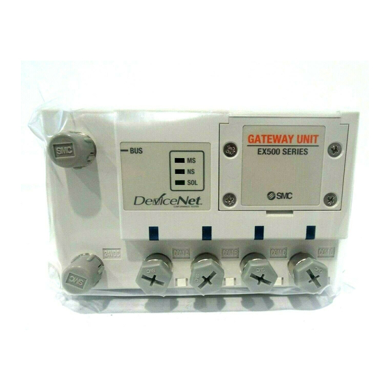
EX500 Serial System EX## - OME0008 5 -2. Parts description Fieldbus connector LED display window (DeviceNet) Station switch protection cover Power supply connector Communication port A Communication port B Communication port C Communication port D a. Fieldbus connector : Port for PLC connection. -
Page 24: Operation Setting
EX500 Serial System EX## - OME0008 5 -3. LED display GATEWAY UNIT EX500 SERIES COM A COM B COM C COM D Display Content Operating in a normal condition : Green lights Recoverable fault ( Memory is abnormal ) : Red lights... -
Page 25: Data Rate Setting Switch ( Sw3 )
EX500 Serial System EX## - OME0008 5 -4 -1. Address setting switch ( SW1, 2 ) These switches set node address. The setting is shown in Table 1. 5 -4 -2. Data rate setting switch ( SW3 ) This switch set data rate. The setting is shown in Table 2. -
Page 26: How To Operate Ex500 - Gpr1 ( Profibus - Dp )
EX500 Serial System EX## - OME0008 6. How to operate EX500 - GPR1 ( PROFIBUS-DP ) 6 -1. Communication wiring ・ ・ ・ ・ Cable specification A twisted pair cable with shield is used in the Impedance 135 ohms to 165 ohms communication wiring of PROFIBUS- DP. -
Page 27: Led Display
EX500 Serial System EX## - OME0008 6 -3. LED display GATEWAY UNIT EX500 SERIES PROCESS FIELD BUS B U S COM A COM B COM C COM D Display Content Source ON : Lights Source OFF : Lights off Solenoid valve source voltage is normal... -
Page 28: Terminating Resistance Setting Switch ( Sw4 )
EX500 Serial System EX## - OME0008 6 -4 -1. Address setting switch ( SW1, 2, 3 ) These switches set node address. The setting is shown in the following figure. The address per one segment can be set in 32 node in case of no Repeater used and is set a maximum of 126 node in case of a Repeater used. - Page 29 EX500 Serial System EX## - OME0008 ・ ・ ・ ・ In case of corresponding with “ Double Word “ Data ( 4 byte ) Branch ( m,n=0 - ) connector COM A Double Word Byte (m) Byte (m+1) Byte (m+2)
-
Page 30: Input Unit Manifold
7. Input Unit Manifold 7 -1. Parts description The Input Unit Manifold is composed of Input Unit ( EX500 - IB1 ( -X1 ) ), Input Block ( EX500 - IE□ ( -X1 ) ), End Block and DIN rail. -
Page 31: Exploded View / Input Unit Manifold
Parts name Note For standard For RIO ① Input Unit EX500 - IB1 EX500 - IB1 -X1 Input Block ② EX500 - IE□ EX500 - IE□ -X1 PNP … □: 1, NPN … □: 2 ( M8 connector ) Input Block ③... -
Page 32: Manifold Valve
EX500 Serial System EX## - OME0008 8. Manifold Valve 8 -1. Parts description Refer to the Catalogues or Technical Instruction Manual of SV and VQC series Manifold Valve for more details. SV series Power LED Communication LED Communication connector ( C1 ) -
Page 33: Correspondence Of Output Number And Manifold Valve
EX500 Serial System EX## - OME0008 8 -2.Correspondence of output number and Manifold Valve The output number to the Manifold Valve of the SI Unit is shown in the following figure. The SI Unit has output of 16 points. In case of the Relay Output Module ( 1 output ), it becomes like the Single solenoid valve. -
Page 34: How To Install The Si Unit
EX500 Serial System EX## - OME0008 8 -3. How to install the SI Unit The following figure shows how to install / remove the SI Unit with / from the Manifold Valve. Refer to the Catalogues or Technical Instruction Manual of SV and VQC series Manifold Valve for more details. -
Page 35: Wiring
Gray : PE Blue : 0V ( for power source) 24V DC Black : 24V DC ±10% ( for power source) 24V DC P/N : EX500 - AP ※※※ ※※※ - ※ ※ ※ ※ ※※※ ※※※ Power connector for GW Unit B. -
Page 36: Communication Wiring
9 -2. Communication wiring 9 -2 -1. Communication wiring to PLC A. Remote I/O ( EX500 - GAB1 -X1 ) communication wiring Remote I/O communication cable can be connected with any of the two M12, 4 pin connectors on GW Unit. -
Page 37: Dimension
EX500 Serial System EX## - OME0008 10. Dimension 10 -1. Gateway ( GW ) Unit 10 -2. Input Unit Manifold ・ ・ ・ ・ In case of M8 Input Block ( Pitch ) P=12 DIN rail ( L4 ) ( Rail mounting pitch : 12.5 ) -
Page 38: Manifold Valve
EX500 Serial System EX## - OME0008 ・ ・ ・ ・ In case of M12 Input Block ( Pitch ) DIN rail P=20 (L4) ( Rail mounting pitch :12.5 ) EX500-IE3 EX500-IE3 EX500-IE3 EX500-IE3 EX500-IE3 EX500-IE3 EX500-IB1 EX500-IE3 EX500-IE3 (PNP) (PNP) -
Page 39: Trouble Shooting
EX500 Serial System EX## - OME0008 11. Trouble shooting ・ ・ ・ ・ Whole system Item Remedies The solenoid valve does not work. ・ Check the power supply for the solenoid valve is supplying 24VDC. ( Refer to section 9 -1 ) ・Check the Branch Cable with M12 Connector is properly... - Page 40 EX500 Serial System EX## - OME0008 ・ ・ ・ ・ DeviceNet communication Item Remedies The status of MS LED ・Check the signal line from PLC is properly connected. Operating in a normal condition ( Refer to section 5 -2 ) : Green lights ・Check Wiring and pin out.