Table of Contents
Advertisement
Quick Links
COUNTERTOP STEAMERS
Model EZ-3
Improper installation, operation, service, or maintenance can cause property damage, injury, or death.
Read this manual thoroughly before installing and operating this equipment.
M
1178387
5
ANUAL
REV
$18.00
OPERATOR'S MANUAL
FOR MODEL EZ-3 and EZ-5
Simple Steam
1100 Old Honeycutt Road, Fuquay-Varina, NC 27526
www.southbendnc.com
WARNING
IMPORTANT FOR FUTURE REFERENCE
Please complete this information and retain this
manual for the life of the equipment:
Model #: ___________________________
Serial #: ___________________________
Date Purchased: ____________________
Model EZ-5
EZ COUNTERTOP STEAMERS
MANUAL SECTION ST
Advertisement
Chapters
Table of Contents

Related Manuals for Southbend EZ-3/EZ-5


Summary of Contents for Southbend EZ-3/EZ-5
- Page 1 OPERATOR’S MANUAL FOR MODEL EZ-3 and EZ-5 COUNTERTOP STEAMERS Model EZ-3 Improper installation, operation, service, or maintenance can cause property damage, injury, or death. Read this manual thoroughly before installing and operating this equipment. 1100 Old Honeycutt Road, Fuquay-Varina, NC 27526 1178387 ANUAL $18.00...
-
Page 2: Safety Precautions
SAFETY PRECAUTIONS Before installing and operating this equipment, be sure everyone involved in its operation is fully trained and aware of precautions. Accidents and problems can be caused by failure to follow fundamental rules and precautions. The following symbols, found throughout this manual, alert you to potentially dangerous conditions to the operator, service personnel, or to the equipment. -
Page 3: Table Of Contents
Congratulations! You have purchased one of the finest pieces of heavy-duty commercial cooking equipment on the market. You will find that your new equipment, like all Southbend equipment, has been designed and manufactured to meet the toughest standards in the industry. Each piece of Southbend equipment is carefully engineered and designs are verified through laboratory tests and field installations. -
Page 4: Specifications
PECIFICATIONS PECIFICATIONS DIMENSIONS 16-1/2" (419) Height (see table below) 4" Adjustable Legs FRONT VIEW Interior Dimensions Height Model Width Depth 21" 13-1/2" 22" EZ-3 (533) (343) (559) 27-1/8" 13-1/2" 22" EZ-5 (689) (343) (559) * Add 4" to height if 4" adjustable legs are used. ** “Pan Capacity”... -
Page 5: Installation
EZ-3 & EZ-5 C ODEL OUNTERTOP NSTALLATION DO NOT CONNECT 3/4" ID GREY HOSE IN REAR OF UNIT TO ANYTHING. THESE ARE VENT HOSES AND MUST BE ALLOWED TO DRAIN INTO PAN. FAILURE TO COMPLY COULD CAUSE A DANGEROUS PRESSURE RISE INSIDE OF THE STEAMER. Do not locate unit adjacent to any high heat or grease producing piece of equipment, such as a range top, griddle, fryer, etc., that could allow radiant heat to raise the exterior temperature of the steam body above 130°F (54°C). - Page 6 NSTALLATION Step 2: Install the Legs 1. Uncrate carefully. Report any hidden damage to the freight carrier IMMEDIATELY. 2. Do not remove any tags or labels until unit is installed and working properly. 3. Remove placeholder bolts holding bottom cover onto unit and discard. 4.
- Page 7 EZ-3 & EZ-5 C ODEL OUNTERTOP Step 3: Electric Connection A field connection terminal block is located at the rear of the unit, lower left side. A hole is provided for a 3/4" conduit fitting (solid or flex). The rear cover must be removed to gain access to terminal block (see Figure 2). Be sure that the input voltage matches the requirement on the serial plate.
- Page 8 NSTALLATION Step 4: Optional Floor Drain The drain valve is 1/2" NPT. Position the unit near, but not on top of, an open floor drain. Allow at least a 1" air gap. DO NOT directly plumb to the unit unless you also install an “open funnel” downstream of this connection in the drain system.
-
Page 9: Operation
EZ-3 & EZ-5 C ODEL OUNTERTOP PERATION STARTUP 1. If the cavity bottom cover is present, open door and remove. 2. Turn lever to “ON” position with door open. 3. Important: Pour water into trough above the door until water is observed passing through the fill / drain opening at left rear corner of cavity bottom. -
Page 10: Cooking Hints
OOKING INTS OOKING INTS COOKING TIPS Schedule cooking of fresh vegetables so that they will be served soon after they are cooked. If it is necessary to prepare them in advance, they can be plunged into cold water, drained thoroughly and held under refrigeration until needed for service. - Page 11 EZ-3 & EZ-5 C ODEL OUNTERTOP Table continuing from previous page. Product Mixed Vegetables Frozen Peas Frozen Potatoes Red Bliss - Whole Russetts - Whole Russetts - Peeled Russetts 1-Inch Cubes Spinach Fresh, Leaf Frozen, Chopped Zucchini Fresh - Slices ¼-inch Thick Broccoli Spears -Fresh Spears - Frozen (Thawed)
- Page 12 OOKING INTS Table continuing from previous page. Product Black Eyed Peas Place beans in pan and cover with 3-quarts hot tap water. Steam for 2 minutes; remove from steamer and cover for 1 hour. Remove cover and place back in steamer for 35 minutes. Oysters Shrimp, Fresh, Medium, Heads Removed Shrimp, Frozen, Large, Peeled &...
-
Page 13: Cleaning
7. Leave the door open at night after cleaning to prolong the life of the gasket. PERIODIC CLEANING • If lime or mineral deposit starts to build up in the interior, clean the unit by using Southbend “descaler” or other non-caustic deliming solution. Follow manufacturer’s recommended procedures. Thoroughly rinse out unit with clean water. - Page 14 Refinishing may then be required. SEMIANNUAL CLEANING At least twice a year, have your Southbend Authorized Service Agency or another qualified service technician clean and adjust the unit for maximum performance. Semiannual cleaning should include the following: 1.
-
Page 15: Troubleshooting
EZ-3 & EZ-5 C ODEL OUNTERTOP ROUBLESHOOTING This section contains a troubleshooting flowcharts, procedures, and electric schematics to assist a qualified service technician in the servicing of a EZ-3 or EZ-5 Countertop Steamer. TROUBLESHOOTING FLOWCHARTS Find the symptom below that corresponds to the malfunction, then turn to the corresponding figure and page. Follow the flowchart on that page until the problem is solved. -
Page 16: Unit Not Heating Up, "On" Light Not Lit
ROUBLESHOOTING Figure 4 Unit Not Heating Up, “ON” Light Not Lit Check that circuit breaker is “ON” and that proper voltage is available at terminal block. (For units with a fuse block, check for proper voltage at both ends of each fuse. Replace as necessary.) DISCONNECT POWER AT CIRCUIT BREAKER Remove control panel without disconnecting plug. -
Page 17: Unit Not Heating Up Properly Or Not Cooking As Fast, "On" Light Lit
EZ-3 & EZ-5 C ODEL OUNTERTOP Figure 5 Unit Not Heating Up Properly or Not Cooking As Fast, “ON” Light Lit Unit not heating up properly, or not cooking as fast, “ON” light lit. Check all main fuses or circuit breaker, replace as necessary. Drain unit. -
Page 18: Unit Using Excessive Amount Of Water And/Or Excessive Steam Coming From Vent Tube
ROUBLESHOOTING Figure 6 Unit Using Excessive Amount of Water and/or Excessive Steam Coming from Vent Tube Unit using excessive amount of water and/or excessive steam coming from vent tube behind the unit. DISCONNECT POWER AT CIRCUIT BREAKER Remove control panel, but leave plug connected. Disconnect wire between float switch and controller (see applicable wiring diagram), reconnect power, turn unit on, and wait 12 minutes. -
Page 19: Buzzer Does Not Come On
EZ-3 & EZ-5 C ODEL OUNTERTOP Figure 8 Buzzer Does Not Come On DISCONNECT POWER AT CIRCUIT BREAKER Remove buzzer lead wires from timer. Check timer (see Figure 15 on page 26). Continuity? Replace timer. Replace buzzer (see Figure 15 on page 26). ’... -
Page 20: Voltage Check At Control Panel Fuse Block
ROUBLESHOOTING Figure 9 Voltage Check at Control Panel Fuse Block Control Panel Fuse Block 1. Disconnect power at circuit breaker. 2. Remove control panel without disconnecting plug. 3. Turn lever to “ON” position. 4. Reconnect power. 5. Place leads as shown. 6. -
Page 21: Heating Element Resistance Check (At Contactor)
EZ-3 & EZ-5 C ODEL OUNTERTOP Figure 10 Heating Element Resistance Check (at contactor) 1. Disconnect power at circuit breaker. 2. Remove control panel. 3. Place test leads between terminals A and C on left side of contactor. 4. Check the resistance and compare to the allowable range in the following table: Voltage 5. -
Page 22: Main Fuse Replacement (For Units Built Before July 1, 2002)
ROUBLESHOOTING EZ-3 & EZ-5 C ODEL OUNTERTOP TEAMERS Figure 11 Main Fuse Replacement (for units built before July 1, 2002) Fuse Block Fuse Block Cover (shown removed) Rear Cover 1. Disconnect power at circuit breaker. 2. Remove rear cover from unit. 3. -
Page 23: Power Switch Continuity Check
EZ-3 & EZ-5 C ODEL OUNTERTOP Figure 12 Power Switch Continuity Check "NO" Lead 1. Disconnect power at circuit breaker. 2. Remove control panel. 3. Turn Lever to “ON” from “OFF” and to “OFF” from “ON” ensuring that the power switch is properly actuated. -
Page 24: Contactor Coil And Mov Check
ROUBLESHOOTING Figure 13 Contactor Coil and MOV Check TOP VIEW 1. Disconnect power at circuit breaker. 2. Remove control panel and disconnect nine-pin plug PL1. 3. Depress actuator on top of contactor. Actuator should travel freely and spring back when released. 4. -
Page 25: Idle Element Resistance Check (For Units Built Before January 15, 2001)
EZ-3 & EZ-5 C ODEL OUNTERTOP Figure 14 Idle Element Resistance Check (for units built before January 15, 2001) Model EZ-3 1. Disconnect power at circuit breaker. 2. Remove control panel. 3. Disconnect idle element plug (PL3). 4. Place test leads as shown above. 5. -
Page 26: Timer And Buzzer Check
ROUBLESHOOTING EZ-3 & EZ-5 C ODEL OUNTERTOP TEAMERS Figure 15 Timer and Buzzer Check Timer Buzzer 1. Disconnect power at circuit breaker. 2. Remove control panel. 3. Set timer for one minute and allow to time out. If timer does not run, then replace. 4. -
Page 27: Door Switch Continuity Check (For Units Built Before January 15, 2001)
EZ-3 & EZ-5 C ODEL OUNTERTOP Figure 16 Door Switch Continuity Check (for units built before January 15, 2001) Model EZ-3 Terminal Block 1. Disconnect power at circuit breaker. 2. Remove control panel. 3. Depress and release door switch actuator rod to make sure door switch is properly actuated. 4. -
Page 28: Door Switch Continuity Check (For Units Built After January 15, 2001)
ROUBLESHOOTING EZ-3 & EZ-5 C ODEL OUNTERTOP TEAMERS Figure 17 Door Switch Continuity Check (for units built after January 15, 2001) Terminal Block Door Switch 1. Disconnect power at circuit breaker. 2. Remove control panel. 3. Depress and release door switch actuator rod to make sure door switch is properly actuated. 4. -
Page 29: Float Switch Continuity Check
EZ-3 & EZ-5 C ODEL OUNTERTOP Figure 18 Float Switch Continuity Check Water Passages Float Switch Coupling Float Tube Assembly 1. Disconnect power at circuit breaker. 2. Remove rear cover from unit. 3. Disconnect 2 pin float switch plug from mating plug on back of unit (PL2). 4. -
Page 30: High Limit Continuity Check (For Units Built Before January 15, 2001)
ROUBLESHOOTING Figure 19 High Limit Continuity Check (for units built before January 15, 2001) Model EZ-3 1. Turn unit off. 2. Wait for cavity bottom to cool to touch. 3. Disconnect power at circuit breaker. 4. Remove control panel without disconnecting plug. 5. -
Page 31: High Limit Continuity Check (For Units Built After January 15, 2001)
EZ-3 & EZ-5 C ODEL OUNTERTOP Figure 20 High Limit Continuity Check (for units built after January 15, 2001) 1. Turn unit off. 2. Wait for cavity bottom to cool to touch. 3. Disconnect power at circuit breaker. 4. Remove control panel without disconnecting plug. 5. -
Page 32: Time Delay Relay Check (For Ez-3 Units Built Before January 15, 2001)
ROUBLESHOOTING Figure 21 Time Delay Relay Check (for EZ-3 units built before January 15, 2001) 1. Disconnect power at circuit breaker. 2. Remove control panel, but leave plugged in. 3. Disconnect wire C23 from terminal block position 3. 4. Reconnect power. 5. -
Page 33: Controller Check (For Ez-5 Units And For Ez-3 Units Built After January 15, 2001)
EZ-3 & EZ-5 C ODEL OUNTERTOP Figure 22 Controller Check (for all EZ-5 units and for EZ-3 units built after Jan. 15, 2001) Step Door Switch (SW2) #8 Float Switch (SW1) #7-#9 Door Open Door Open to Close Door Closed Pressurized, Down Position Door Closed Normal Cycle Operation... -
Page 34: Electric Schematic For 208-240 Volt 60 Hz Or 220 Volt 50 Hz Model Ez-3 Units Built Before Jan. 15, 2001
ROUBLESHOOTING EZ-3 & EZ-5 C ODEL OUNTERTOP TEAMERS Figure 23 Electric Schematic for 208-240 Volt 60 Hz or 220 Volt 50 Hz Model EZ-3 Units Built Before January 15, 2001 ’ 1178387 PERATOR ANUAL... -
Page 35: Electric Schematic For 480 Volt Model Ez-3 Units Built Before Jan. 15, 2001
ROUBLESHOOTING EZ-3 & EZ-5 C ODEL OUNTERTOP TEAMERS Figure 24 Electric Schematic for 480 Volt Model EZ-3 Units Built Before January 15, 2001 ’ 1178387 PERATOR ANUAL... -
Page 36: Electric Schematic For 208-240 Volt 60 Hz Or 220 Volt 50 Hz Model Ez-5 Units Built Before Jan. 15, 2001
ROUBLESHOOTING EZ-3 & EZ-5 C ODEL OUNTERTOP TEAMERS Figure 25 Electric Schematic for 208-240 Volt 60 Hz or 220 Volt 50 Hz Model EZ-5 Units Built Before January 15, 2001 ’ 1178387 PERATOR ANUAL... -
Page 37: Electric Schematic For 480 Volt Model Ez-5 Units Built Before Jan. 15, 2001
ROUBLESHOOTING EZ-3 & EZ-5 C ODEL OUNTERTOP TEAMERS Figure 26 Electric Schematic for 480 Volt Model EZ-5 Units Built Before January 15, 2001 ’ 1178387 PERATOR ANUAL... -
Page 38: Electric Schematic For 208-240 Volt 60 Hz Or 220 Volt 50 Hz Units (Ez-3 Or Ez-5) Built After Jan. 15, 2001
ROUBLESHOOTING EZ-3 & EZ-5 C ODEL OUNTERTOP TEAMERS Figure 27 Electric Schematic for 208-240 Volt 60 Hz or 220 Volt 50 Hz Units (EZ-3 or EZ-5) Built After January 15, 2001 ’ 1178387 PERATOR ANUAL... -
Page 39: Electric Schematic For 480 Volt Units (Ez-3 Or Ez-5) Built After January 15, 2001
ROUBLESHOOTING EZ-3 & EZ-5 C ODEL OUNTERTOP TEAMERS Figure 28 Electric Schematic for 480 Volt Units (EZ-3 or EZ-5) Built After January 15, 2001 ’ 1178387 PERATOR ANUAL... -
Page 40: Parts
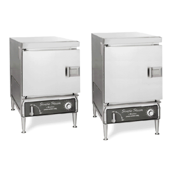
On tandem units, a second tag is on the right side of the right unit and the left side of the left unit. Replacement parts may be ordered either through a Southbend Authorized Parts Distributor or a Southbend Authorized Service Agency. - Page 41 ODEL OUNTERTOP Parts for Simple Steam Countertop Steamer EZ-3 Part Number EZ-5 Part Number Description - 1178397 CONTROL PANEL ASSEMBLY (for EZ-3 units built before January 15, 2001) 1181042 1181042 CONTROL PANEL ASSEMBLY (for all EZ-5 units and for EZ-3 units built after January 15, 2001) 1178311 1178311 CONTROL PANEL WELDED ASSEMBLY ONLY...
- Page 42 Parts for Simple Steam Countertop Steamer EZ-3 Part Number EZ-5 Part Number *See Note 1181500 1181502 PN126 *See Note 1181500 1181502 PN126 1161525 1161525 1173448 1181032 1181032 1178355 1178361 1178358 1178364 1181500 1181500 1178353 1178359 1178560 1178561 1178565 1178562 1178554 1178555 1178556 1178559...
- Page 43 ODEL OUNTERTOP Parts for Simple Steam Countertop Steamer EZ-3 Part Number EZ-5 Part Number Description - 1178389 BUSSMAN FUSE BLOCK,30A (for units built before July 1, 2002) 1178494 1178494 BUSSMAN FUSE BLOCK,60A 48 (for units built before July 1, 2002) 1179962 1179962 COVER,REMOVABLE BUSS(for units built before July 1, 2002)
- Page 44 Parts for Simple Steam Countertop Steamer EZ-3 Part Number EZ-5 Part Number 1178370 1181022 1178369 1181021 1178371 1178371 1181583 1181583 1178418 1178418 1181753 1181753 1178265 1178265 1178365 1178527 1181000 1182536 1182537 1178255 1181009 1178656 1178657 1178227 1178234 1178439 1178439 1178324 1178324 1178113 1181045...
- Page 45 When service is needed, contact a Southbend Authorized Service Agency, or your dealer. To avoid confusion, always refer to the model number, serial number, and type of your unit.