Advertisement
Available languages
Available languages
Quick Links
TRANSOM TRANSDUCER Installation Guide
The transom mount installation allows adjustment of both running angle and depth after the
transducer is mounted, which enables you to tune the installation for best results.
NOTE: Due to the wide variety of hulls, only general instructions are presented in this installation
guide. Each boat hull represents a unique set of requirements that should be evaluated prior to
installation. For detailed information about installing transducers on different hull types,
download the Transducer Installation Resource Guide from our Web site at humminbird.com.
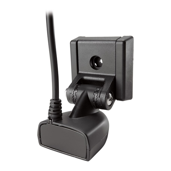
NOTE: Your transducer may not look exactly like the transducer shown in the illustrations, but it
will mount in exactly the same way.
Install the control head before you start the transducer installation. See the control head
installation guide.
Review your boat manufacturer's owner's manual for recommended transducer installation
locations and cable routing methods. You will also need your transom angle.
Read and understand your boat's warranty before starting this installation.
Read the instructions in this guide completely and understand the mounting guidelines
before beginning this installation.
Visit our Web site at humminbird.com for additional information and resources for transducer
installations. Also, visit youtube.com/humminbirdtv for informational videos.
Confirm your boat is level for the installation.
Consider your speed requirements.
Traveling over 65 mph with the transducer in the water is not recommended with the XNT 9
SI 180 T, XNT 9 DB 74 T, XNT 14 74 T, and XNT 9 MSI 150 T transducers, as damage may occur.
If speed above 65 mph is critical, see the FAQ (Frequently Asked Questions) section of our Web
site at humminbird.com.
Down Imaging® provides the maximum detail at slower speeds, however, high-speed
performance is available in the Down Imaging and traditional sonar views. If high-speed
operation is critical with your Down Imaging transducer, you may want to consider an Inside
the Hull transducer.
SIDE IMAGING® NOTE: The Side Imaging transducer CANNOT be installed inside the hull of
the boat.
Supplies: In addition to the supplied hardware, you will need a powered hand drill and various
drill bits, various hand tools, including a ruler or straightedge, a level, a socket driver, marker
or pencil, safety glasses and dust mask, marine-grade silicone sealant, dielectric grease
(optional), and a 12" plumb line (weighted string or monofilament line [optional]). You may
also need extension cables and hardware for routing the cable to the control head.
Installation Preparation
1
532314-3_B
Advertisement

Related Manuals for Humminbird XNT 9 DB 74 T


Summary of Contents for Humminbird XNT 9 DB 74 T
- Page 1 Traveling over 65 mph with the transducer in the water is not recommended with the XNT 9 SI 180 T, XNT 9 DB 74 T, XNT 14 74 T, and XNT 9 MSI 150 T transducers, as damage may occur.
- Page 2 TRANSOM TRANSDUCER Installation Guide 532314-3_B Turbulence-Free Mounting Guidelines It is very important to locate the transducer in an area that is relatively free of turbulent water. Consider the following to find the best location with the least amount of turbulence: Avoid areas where there is turbulent water flow.
- Page 3 1 for the ratchets. 1b. If you have a different transom angle or do not know your transom angle, refer to the Transducer Installation Resource Guide on our Web site at humminbird.com for detailed instructions. 2. Place the two ratchets, one on either side of the transducer knuckle, so that the beads on each ratchet line up with the desired position number on the knuckle (see Installing the Ratchets in Position 1).
- Page 4 TRANSOM TRANSDUCER Installation Guide 532314-3_B NOTE: If the pivot assembly is snapped closed over the mounting bracket, use a flat head screwdriver or similar tool to gently pry the assembly away from the mounting bracket. 6. Align the mounting bracket transducer assembly with the drilled holes in the transom. With a 5/16" socket driver, mount the assembly to the transom using the two #10 - 1"...
- Page 5 If the cable is too short, extension cables are available to extend the transducer cable up to a total of 50'. For assistance, contact Humminbird® Technical Support. CAUTION! Do NOT mount the cables where the connectors could be submerged in water or flooded.
- Page 6 TRANSOM TRANSDUCER Installation Guide 532314-3_B | Test and Finish the Installation Once you have installed the control head, the transducer, and have routed all the cables, you must perform a final test before locking the transducer in place. Testing should be performed with the boat in water deeper than 2 feet. The transducer should be fully submerged because the sonar signal cannot pass through air.
- Page 7 If a compatible accessory transducer is connected, you will need to set the transducer type on the control head. When you select the transducer type, the related views and menus will be added to the system. Δ For additional configuration information, download the control head operations manual from our Web site at humminbird.com.
-
Page 8: Maintenance
WARNING! The transducer must be fully submerged in water during operation because the sonar signal cannot pass through air. Air pinging can damage the transducer. NOTE: Download Humminbird installation guides and operations manuals from our Web site at humminbird.com. NOTE: Product specifications and features are subject to change without notice. -
Page 9: Préparation De L'installation
Voyager à plus de 65 km / h avec le transducteur dans l'eau n'est pas recommandé avec les transducteurs XNT 9 SI 180 T, XNT 9 DB 74 T, XNT 14 74 T et XNT 9 MSI 150 T, car ils peuvent être endommagés. - Page 10 TRANSDUCTEUR TRANSOM Guide d'Installation 532314-3_B Directives de montage sans turbulence Il est très important de positionner le transducteur à un endroit relativement libre de turbulences. Tenez compte des facteurs suivants pour déterminer l’emplacement où il y aura le moins de turbulences.
- Page 11 1b. Si vous avez un angle de traverse différent ou ne connaissez pas votre angle de traverse, reportez-vous au Guide de ressources d'installation du transducteur sur notre site Web à humminbird.com pour obtenir des instructions détaillées. 2. Placez les deux mécanismes à rochet de chaque côté du joint d’articulation du transducteur, de façon à...
- Page 12 TRANSDUCTEUR TRANSOM Guide d'Installation 532314-3_B Insertion du boulon pivot REMARQUE : Les mécanismes à rochet sont clavetés. Assurez-vous que les dents carrées de chaque mécanisme à rochet s’imbriquent dans celles du joint d’articulation du transducteur et que les dents triangulaires font face vers l’extérieur. 3.
- Page 13 TRANSDUCTEUR TRANSOM Guide d'Installation 532314-3_B Ajustement de l'angle initial du transducteur Réglage de l'angle du transducteur horizontal Bord d’attaque (le bord le plus près du tableau arrière du bateau). Un clic trop haut : le transducteur est incliné hors de l'eau et ne peut pas maintenir un signal sonar.
- Page 14 15 m (50 pi). Pour obtenir de l’aide, communiquez avec le support technique Humminbird. MISE EN GARDE ! Ne montez PAS les câbles dans un endroit où les connecteurs pourraient être submergés.
- Page 15 TRANSDUCTEUR TRANSOM Guide d'Installation 532314-3_B Si l’appareil fonctionne correctement, augmentez progressivement la vitesse du bateau pour Serrez complètement tester le rendement à grande vitesse. Si l’appareil fonctionne adéquatement à basse vitesse les trois vis de fixation mais que la représentation du fond devient erratique à vitesse plus élevée, il faut ajuster la position du transducteur.
-
Page 16: Entretien
REMARQUE : Les guides d'utilisation et d'installation sont vues et menus associés sont ajoutés au système. téléchargeables sur notre site Web à l'adresse humminbird.com. Δ Pour plus d'informations sur la configuration, téléchargez le REMARQUE : Les caractéristiques et spécifications de ce produit manuel d'utilisation de la tête de commande sur notre site...