Table of Contents
Advertisement
Advertisement
Table of Contents

Related Manuals for Humminbird MEGA 360 IMAGING Series


Summary of Contents for Humminbird MEGA 360 IMAGING Series
- Page 1 MEGA 360 IMAGING INSTALLATION GUIDE 532684-1_A...
- Page 2 Always operate the boat at very slow speeds if you suspect shallow water or submerged objects. WARNING! The electronic chart in your Humminbird unit is an aid to navigation designed to facilitate the use of authorized government charts, not to replace them.
- Page 3 Languages, maps, time zones, units of measurement, and warranty are examples of features that are customized for Humminbird international units purchased through our authorized international distributors. To obtain a list of authorized international distributors, please visit our Web site at humminbird.com or contact Humminbird Technical Support at...
-
Page 4: Table Of Contents
Table of Contents Introduction Compatibility ................1 Supplies . - Page 5 Finding the Cause of Noise ............. 40 Specifications Contact Humminbird...
-
Page 7: Introduction
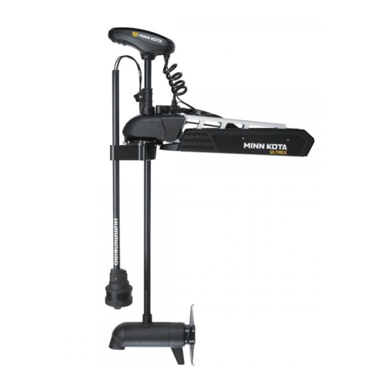
Control Heads: MEGA 360 Imaging is compatible with SOLIX Series and HELIX Series fish finders equipped with MEGA Imaging+ and can be mounted on Minn Kota Ultrex, Fortrex, and Maxxum bow-mount trolling motors. MEGA 360 Imaging Minn Kota Trolling Motor Humminbird Fish Finder SOLIX Series: SOLIX G2 models MEGA 360 Ultrex... - Page 8 NOTE: If a MEGA SI+ transducer is connected with one of these y-cables, the Humminbird unit will not be able to get SI data from the MEGA SI+ transducer – only HW and MEGA DI+ will be available. However, the user can get MEGA SI data from the MEGA 360 transducer.
-
Page 9: Supplies
GPS Puck, a Heading Sensor GPS Adapter (SOLIX only), and transducer extension cables. For the most current list of compatible accessories, visit our Web site at humminbird.com. Supplies In addition to the hardware included with your accessory, you will need the following supplies: •... -
Page 10: Update Software
Update Software Your control head model may need a software update to work with the MEGA 360 Imaging transducer. We recommend that you read the following section completely before starting any software updates. Software Requirements • SOLIX G2 Series: 3.520 or higher •... -
Page 11: Update Control Head Software With An Sd Card
Update Control Head Software with an SD Card You will need an SD or microSD card (depending on your control head model). WARNING! Humminbird is not responsible for the loss of data files (waypoints, routes, tracks, groups, snapshots, recordings, etc.) that may occur due to direct or indirect damage to the unit’s hardware or software. -
Page 12: Update Accessory Software With An Sd Card
You will need an SD or microSD card (depending on your control head model). 1. Install a formatted SD or microSD card into the computer card slot. 2. Go to humminbird.com, and click Support > Software Updates. 3. Scroll down to Accessories and Mapping. The available software updates are listed as downloads under each accessory product. -
Page 13: Update Software With Fishsmart
Update Software with FishSmart You can use the FishSmart App to download and push software updates directly to your Humminbird control head or accessory. NOTE: Your control head must already be running software release 1.610 or higher for HELIX Series or 3.110 or higher for SOLIX Series to support this feature. -
Page 14: Install The Trolling Motor Bracket
Install the Trolling Motor Bracket Use the following instructions to install the MEGA 360 Imaging transducer on your Minn Kota trolling motor. It is important to read the instructions completely and understand the mounting guidelines before you start the installation. 1. -
Page 15: Install The Trolling Motor Bracket
2. Install the Trolling Motor Bracket Proceed to the installation section of the type of trolling motor bracket you purchased: A. Ultrex Trolling Motor Mount (MEGA 360 Ultrex) B. Fortrex/Maxxum Trolling Motor Mount (MEGA 360 Fortrex) A. Ultrex Trolling Motor Mount (MEGA 360 Ultrex) WARNING! Disconnect the motor from all sources of electrical power before you start installation. - Page 16 Positioning the Bracket for Installation on the Left Side of Trolling Motor straight edge round edge on the left on the right pod route If the trolling motor deploys port side (left) on the bow, you will mount the bracket on the right side of the trolling motor. Position the bracket so the straight edge faces to the right as shown in the illustration.
- Page 17 5. Align the center hole of the plate over the left screw (left side installation) or right screw (right side installation). 6. Lower the plate onto the screw head, and slide the screw into the plate slot. Slide the other two screws into the outside slots on the plate. If the plate does not slide easily into place, flip it over.
- Page 18 Install the Bracket As determined in the Assemble the Bracket section, the bracket can be mounted on the left or right side of the trolling motor. 1. Align the plate below the BowGuard. Line up the holes on the plate with the threaded holes on the BowGuard.
- Page 19 3. Route the cables and pod shaft up through the trolling motor bracket. 4. Use an Allen wrench (not included) to install the (2) 10-32 x 9/16" socket bolts on the bracket where the pod shaft is installed. 5. Tighten the bolts so the pod shaft is fully secure and won’t drop when it is deployed in the next step.
- Page 20 Adjust the Pod Height 1. Deploy the Trolling Motor. 2. Loosen the socket bolts on the bracket where the pod shaft is installed. Adjust the pod shaft up or down, so it meets the following height requirements: • The pod must be mounted approximately 6" (152.4 mm) below the waterline.
- Page 21 WARNING! Do not install the pod too close to the propeller. If the pod is installed too close to the propeller, it will be damaged. Adjusting the Pod Height (at least 1" from the tip of the propeller) 1" (25.4 mm) minimum shaft length above bracket 1"...
- Page 22 3. Turn the pod shaft until the rounded end of the transducer points in the direction of travel. The centerline of the transducer should be parallel with the centerline of the boat. See the illustration Aligning the Transducer. Aligning the Transducer rounded part of transducer 4.
- Page 23 Install the Collar Clamp After you have established the pod height is no closer than 1 inch from the tip of the propeller, install the collar clamp to prevent the trolling motor from hitting the transducer pod. 1. Apply anti-seize to the end of each 1" socket bolt (1/4-20 x 1"). 2.
- Page 24 5. Use an Allen wrench (not included) to tighten the hardware just enough to keep the collar assembled. 6. Slide the collar up to the base of the BowGuard. 7. Use an Allen wrench (not included) to fully tighten the socket bolts until they are secure.
-
Page 25: Fortrex/Maxxum Trolling Motor Mount (Mega 360 Fortrex)
B. Fortrex/Maxxum Trolling Motor Mount (MEGA 360 Fortrex) WARNING! Disconnect the motor from all sources of electrical power before you start installation. WARNING! Confirm that the trolling motor is properly secured to the boat and will not shift during the installation. The trolling motor should be in the fully retracted (flat) position on the boat deck for this installation. - Page 26 3. Adjust the pod shaft up or down, so the pod is at least 1" (25.4 mm) off the tip of the propeller. WARNING! DO NOT INSTALL THE POD TOO CLOSE TO THE PROPELLER. If the pod is installed too close to the propeller, it will be damaged. Adjusting the Pod Height (at least 1"...
- Page 27 4. Pivot the bracket until the pod is at least 2" (50.8 mm) from the lift assist base and at least 1/2" (13 mm) from the trolling motor shaft. See the illustration Measuring the Safety Distance of the Pod and Positioning the Bracket. WARNING! The pod must not hit the trolling motor shaft, lift assist base, or any objects.
- Page 28 6. Use an Allen wrench (not included) to install the (2) 10-32 x 5/8" hex socket bolts on the bracket where the pod shaft is installed (see the illustration Securing the Pod). Tighten the bolts so the pod shaft is fully secure and won’t drop when it is deployed in the next step.
- Page 29 8. Turn the pod shaft until the rounded end of the transducer points in the direction of travel. The centerline of the transducer should be parallel with the centerline of the boat. See the illustration Aligning the Transducer. NOTE: You might need to loosen the hex socket bolts to adjust the transducer alignment.
- Page 30 11. Install the large insert into the slotted side of the clamp. Use a Phillips screwdriver to install the #8-1/2" screw through the clamp and large insert (see the illustration Installing the Inserts). 12. Install the small insert into the solid side of the clamp. Hold it in place, and re- install the clamp and Depth Collar Knob.
-
Page 31: Route The Cables And Connect Power
(y-cable). See Compatibility for the list of cables, and visit our Web site at www.humminbird.com/support/ installation-diagrams to view the wiring diagrams. 2. Route the cables to the side of the trolling motor, over the bow, to the chosen connection locations in Section 1: Prepare for Installation. - Page 32 3. SOLIX: Insert the other end of the transducer cable to the sonar port on the control head. Hand-tighten the screw nut. SOLIX Sonar-Temp Port HELIX: Insert the transducer adapter cable to the transducer port on the HELIX control head. HELIX 7 Control Head Ports Ethernet power (communications) transducer...
- Page 33 WARNING! The MEGA 360 Imaging transducer should be connected to a main switch, fuse panel, or battery switch. Humminbird does not recommend connecting to a battery without a fuse and a switch. CAUTION! Some boats have 24 or 36 Volt electric systems, but the MEGA 360 Imaging transducer MUST be connected to a 12 VDC power supply.
-
Page 34: Set Up The Control Head
Set Up the Control Head When the control head detects the MEGA 360 Imaging transducer, it will select it automatically as the 360 sonar source. The related views and menus will be added to the system. Use the following instructions to power on the control head and confirm the MEGA 360 Imaging transducer is detected by the unit. - Page 35 NOTE: For additional system status, select Home > Settings > Network > System Info. MEGA 360 Imaging Transducer Connected (SOLIX) MEGA 360 icon on the status bar MEGA 360 Imaging listed as transducer HELIX Series 1. Turn on the power source from the main switch. 2.
-
Page 36: Set Up The Transducer
HELIX Accessory Test MEGA 360 Imaging listed as Connected 2. Set Up the Transducer SOLIX Series Your SOLIX control head will automatically detect the connected transducers. To review the selected sonar sources, open the Settings tool, and select CHIRP Sonar >... -
Page 37: Test Mega 360 Imaging On The Control Head
Selecting the Connected Transducer (HELIX) 3. Test MEGA 360 Imaging on the Control Head It is important to confirm that the MEGA 360 Imaging transducer is providing sonar returns to the display. The instructions in this section should be performed at trolling speeds in calm, open water, in a large area that is far from shallow water, boats, or other obstacles. - Page 38 4. Stop Pinging: When you are finished reviewing the operation, tap Ping Off from the 360 status bar. HELIX Series 1. Press and hold the VIEW key. 2. Select Sonar > 360 View. 3. The sonar returns from the MEGA 360 scan will begin to display on the MEGA 360 View.
-
Page 39: Add Offset Features To The Mega 360 Imaging Display (Optional)
4. Add Offset Features to the MEGA 360 Imaging Display (optional) The menu settings in this section are helpful for interpreting the position of objects on the 360 View. This feature is only available with a connected heading sensor (compass). Adjust the 360 Heading Offset If the positions of objects on the MEGA 360 Imaging display are slightly different than what you observe in the environment around you, use 360 Heading Offset... -
Page 40: Set Up The Network
HELIX Series 1. Main Menu: Press the MENU key twice. 2. Select the Accessories tab > MEGA 360 Settings > 360 Heading Offset. 3. Press the RIGHT or LEFT Cursor keys to change the angle (gray line), and press the CHECK/INFO key to confirm your setting. The zero point on the display is represented by a green line. -
Page 41: Power Off
Power Off WARNING! When the boat is stored or at dock, the MEGA 360 Imaging transducer must be turned off to prevent draining the battery. Power Off the Control Head 1. SOLIX Series: During operation, tap the top, right corner of the status bar or press the POWER key, and select Power Off. -
Page 42: Maintenance
Maintenance Your Humminbird fishfinder is designed to provide years of trouble free operation with very little maintenance. Use the following procedures to ensure your Humminbird continues to deliver top performance. Control Head Maintenance It is important to consider the following precautions when using your Humminbird control head: •... -
Page 43: Transducer Maintenance
Transducer Maintenance Use the following information to maintain the transducer operation. • If your boat remains in the water for long periods of time, algae and other marine growth can reduce the effectiveness of the transducer. Periodically clean the face of the transducer with a cloth dampened with fresh water. •... -
Page 44: Troubleshooting
Troubleshooting Before contacting the Humminbird Technical Support, please read the following section. Taking the time to review these troubleshooting guidelines may allow you to solve a performance problem yourself, and therefore avoid sending your unit back for repair. Fishing System Doesn’t Power Up If your Fishing System doesn’t power up, use the installation guide that is included... -
Page 45: Fishing System Defaults To Simulator With A Transducer Attached
Fishing System Defaults to Simulator with a Transducer Attached In addition to the MEGA 360 Imaging accessory transducer, you will have a standard Humminbird transducer connected to the control head. A connected and functioning transducer with built-in temperature will cause the newly-started Fishing System to go into Normal operating mode automatically. -
Page 46: Finding The Cause Of Noise
Finding the Cause of Noise Electrical noise usually affects the display with streaks or repetitive patterns on the view. One or more of the following sources can cause noise or interference: Possible Source of Noise Isolation Other electronic devices Turn off any nearby electronic devices to see if the problem goes away, then turn them on one at a time to see if the noise re-appears. -
Page 47: Specifications
Operating Temperature ........-4°F to 158°F (-20°C to 70°C) Storage Temperature ........-40°F to 158°F (-40°C to 70°C) NOTE: Humminbird verifies maximum stated depth in saltwater conditions, but actual depth performance may vary due to transducer installation, water type, thermal layers, bottom composition and slope. - Page 48 ROHS STATEMENT: Product designed and intended as a fixed installation or part of a system in a vessel may be considered beyond the scope of Directive 2002/95/EC of the European Parliament and of the Council of 27 January 2003 on the restriction of the use of certain hazardous substances in electrical and electronic equipment.
- Page 49 Notes Notes...
-
Page 50: Contact Humminbird
Contact Humminbird Contact Humminbird Technical Support in any of the following ways: Web site: humminbird.com E-mail: service@humminbird.com Telephone: 1-800-633-1468 Direct Shipping: Humminbird Service Department 678 Humminbird Lane Eufaula, AL 36027 USA Hours of Operation: Monday - Friday 8:00 a.m. to 4:30 p.m. (Central Standard Time) Social Media Resources: Facebook.com/HumminbirdElectronics...