Table of Contents
Advertisement
TRANSOM TRANSDUCER Installation Guide
The transom mount installation allows adjustment of both running angle and depth after the
transducer is mounted, which enables you to tune the installation for best results. It is important
to read the instructions completely and understand the mounting guidelines before beginning this
installation.
NOTE: Due to the wide variety of hulls, only general instructions are presented in this guide. Each
boat hull represents a unique set of requirements that should be evaluated prior to installation.
For detailed information about installing transducers on different hull types, download the
Transducer Installation Resource Guide from our Web site at humminbird.com.
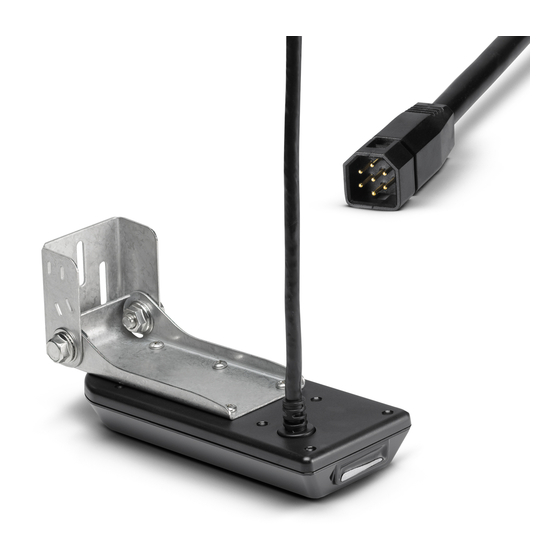
NOTE: Your transducer may not look exactly like the transducer shown in the illustrations, but it
will mount in exactly the same way.
Install the control head before you start the transducer installation. See the control head
installation guide.
Review your boat manufacturer's owner's manual for recommended transducer installation
locations and cable routing methods, as well as your transom and/or deadrise angle.
Read and understand your boat's warranty before starting this installation.
Visit our Web site at humminbird.com for additional information and resources for transducer
installations. Also, visit youtube.com/humminbirdtv for informational videos.
Confirm your boat is level for the installation.
Consider your speed requirements.
Traveling over 65 mph with the transducer in the water is not recommended with the
transom mount transducer, as damage may occur. If speed above 65 mph is critical, see the
FAQ (Frequently Asked Questions) section of our Web site at humminbird.com.
Supplies: In addition to the hardware supplied with your transducer, you will need a powered
hand drill and various drill bits, various hand tools, including a ruler or straightedge, a level,
marker or pencil, Phillips-head screwdriver, flat head screw driver, a socket/nut driver, a 1/2"
(13 mm) wrench and torque wrench, safety glasses and dust mask, marine-grade silicone
sealant, and dielectric grease (optional). You may also need extension cables and hardware for
routing the cable to the control head.
Installation Overview
New Installation: Review Turbulence-Free Mounting Guidelines and proceed to section 1. Mount
the Transom Bracket to the Boat.
Previously-installed Transducer: If you have a previously-installed XHS transducer on the transom,
the bracket in this installation kit can be installed in the same location using the following
instructions:
1. Line up the metal bracket with the previously-used mounting holes to confirm that the two slot
holes match the previous installation. Fill any unused holes with marine-grade silicone sealant.
Installation Preparation
1
532508-4_A
Advertisement
Table of Contents

Related Manuals for Humminbird APEX Series


Summary of Contents for Humminbird APEX Series
- Page 1 Read and understand your boat’s warranty before starting this installation. Visit our Web site at humminbird.com for additional information and resources for transducer installations. Also, visit youtube.com/humminbirdtv for informational videos.
- Page 2 TRANSOM TRANSDUCER Installation Guide 532508-4_A 2. Make sure the boat is level on the trailer (from port to starboard and from bow to stern). 3. Proceed to section 2. Install the Transducer. Turbulence-Free Mounting Guidelines It is very important to locate the transducer in an area that is relatively free of turbulent water. Consider the following to find the best location with the least amount of turbulence: Avoid areas where there is turbulent water flow.
-
Page 3: Install The Transducer
TRANSOM TRANSDUCER Installation Guide 532508-4_A | Mount the Transom Bracket to the Boat 1. Confirm the boat is level on the trailer (both from port to starboard and from bow to stern). 2. Hold the mounting bracket against the transom of the boat in the location you have selected. Align the bracket horizontally, using the level. - Page 4 TRANSOM TRANSDUCER Installation Guide 532508-4_A 4. Install the pivot bolt, 2 washers, and lock nut into the first hole as shown in the illustration Attaching the Transducer Bracket Installing the Transducer Bracket. Repeat for the second hole. 5. Use a 1/2" (13 mm) wrench to tighten the assembly, but do not fully tighten the hardware at 7/16"...
-
Page 5: Connect The Cable
If the cable is too short, extension cables are available to extend the transducer cable up to a total of 50'. For assistance, contact Humminbird® Technical Support. CAUTION! Do NOT mount the cables where the connectors could be submerged in water or flooded. -
Page 6: Maintenance
Hand tighten only! Fully tighten the two pivot bolts, using a 1/2" (13 mm) torque NOTE: Download Humminbird installation guides and operations wrench to 12 ft-lbs. If you don’t have a torque wrench, use a manuals from our Web site at humminbird.com. -
Page 7: Installation Preparation
Accessories and Ethernet: Accessories and Ethernet equipment are available for purchase at humminbird.com. The installation guides are available with the product, or they can be downloaded from our Web site. - Page 8 APEX™ SERIES CONTROL HEAD Installation Guide 532744-1_A 6. Place the assembled control head in various locations to determine the best mounting location with the following requirements: Δ a stable, protected surface to protect the control head from excessive wave shock, vibration, and water Δ...
-
Page 9: Connect Power
WARNING! Make sure that the power cable is disconnected from the control head at the beginning of this procedure. WARNING! Humminbird® is not responsible for over-voltage or over-current failures. The control head must have adequate protection through the proper selection and installation of the fuse size... - Page 10 NOTE: The installation guides for Ethernet and optional-purchase accessories are available with your product, and they can be downloaded from our Web site at humminbird.com. 4. Route all cables to the control head. Your boat may have a pre-existing wiring channel or conduit that you can follow.
- Page 11 Use the smart defaults without the need to customize your unit. Custom mode allows you to see more menu settings for a detailed customization of your unit. For details, download the APEX/SOLIX Operations Manual from humminbird.com. 4. After the setup is confirmed, press the Home key...
- Page 12 Use the Home screen to access settings, alarms, views, and tools. The options are determined by the equipment attached to the control head network. For operations information, see the Quick Start Guide included with your control head and the APEX/SOLIX Operations Manual (available for download at humminbird.com).
- Page 13 Direct Shipping: Humminbird Service Department WEEE DIRECTIVE: EU Directive 2002/96/EC “Waste of Electrical and 678 Humminbird Lane Electronic Equipment Directive (WEEE)” impacts most distributors, Eufaula, AL 36027 USA sellers, and manufacturers of consumer electronics in the European Union. The WEEE Directive requires the producer of consumer electronics...
-
Page 14: Préparation De L'installation
Préparation de l'installation Lisez complètement les instructions de ce guide pour comprendre les directives avant de commencer l'installation. Visitez notre site Web à humminbird.com pour plus d'informations et de ressources sur les installations de transducteurs. Visitez également youtube.com/humminbirdtv pour des vidéos d'information. - Page 15 Technical Support: If you find that any items are missing from your installation kit, visit our Web site at humminbird.com or call Humminbird® Technical Support at 1-800-633-1468. Supplies: In addition to the hardware supplied with your accessory, you will need a drill and various drill bits, a cutting tool for the dashboard material, various hand tools (including a 3/16"...
-
Page 16: Front Mount Installation
APEX™ SERIES IN-DASH MOUNTING Installation Guide 532752-1_A 4. Carefully begin cutting toward the cut line, and continue cutting to the inside of the line around the template. 5. Test the Mounting Hole: Install the control head in the mounting hole to test the fit. Make adjustments to the mounting hole as needed. - Page 17 Cover any unused ports with the tethered caps to prevent potential damage. 4. Your control head is ready for operation. See the Quick Start Guide to get started and download the APEX/SOLIX Operations Manual from our Web site at humminbird.com. screw nut...
-
Page 18: Year Limited Warranty
This does not include shipping replaced free of charge at Humminbird’s option and returned to the time to and from our factory. Units received on Friday are typically customer freight prepaid. -
Page 19: Returning Your Unit For Service
Repair Authorization Number E-mail: service@humminbird.com for your unit. Telephone: 1-800-633-1468 NOTE: Please do not return your Humminbird to the store for service. Direct Shipping: Humminbird Service Department Please have your product model name and serial number available 678 Humminbird Lane before calling the factory.