Table of Contents
Advertisement
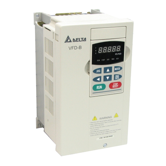
Thank you for choosing DELTA's high-performance VFD-B Series. The VFD-B Series is manufactured with
high-quality components and materials and incorporate the latest microprocessor technology available.
This manual is to be used for the installation, parameter setting, troubleshooting, and daily maintenance of the
AC motor drive. To guarantee safe operation of the equipment, read the following safety guidelines before
connecting power to the AC motor drive. Keep this operating manual at hand and distribute to all users for
reference.
To ensure the safety of operators and equipment, only qualified personnel familiar with AC motor drive are to
do installation, start-up and maintenance. Always read this manual thoroughly before using VFD-B series AC
Motor Drive, especially the WARNING, DANGER and CAUTION notes. Failure to comply may result in
personal injury and equipment damage. If you have any questions, please contact your dealer.
PLEASE READ PRIOR TO INSTALLATION FOR SAFETY.
DANGER!
1. AC input power must be disconnected before any wiring to the AC motor drive is made.
2. A charge may still remain in the DC-link capacitors with hazardous voltages, even if the power has been
turned off. To prevent personal injury, please ensure that power has turned off before opening the AC
motor drive and wait ten minutes for the capacitors to discharge to safe voltage levels.
3. Never reassemble internal components or wiring.
4. The AC motor drive may be destroyed beyond repair if incorrect cables are connected to the input/output
Terminals. Never connect the AC motor drive output terminals U/T1, V/T2, and W/T3 directly to the AC
mains circuit power supply.
5. Ground the VFD-B using the ground terminal. The grounding method must comply with the laws of the
country where the AC motor drive is to be installed. Refer to the Basic Wiring Diagram.
6. VFD-B series is used only to control variable speed of 3-phase induction motors, NOT for 1-phase motors
or other purpose.
7.
VFD-B series shall NOT be used for life support equipment or any life safety situation.
Preface
Advertisement
Table of Contents

Related Manuals for Delta VFD-B Series


Summary of Contents for Delta VFD-B Series
- Page 1 5. Ground the VFD-B using the ground terminal. The grounding method must comply with the laws of the country where the AC motor drive is to be installed. Refer to the Basic Wiring Diagram. 6. VFD-B series is used only to control variable speed of 3-phase induction motors, NOT for 1-phase motors or other purpose.
- Page 2 WARNING! 1. DO NOT use Hi-pot test for internal components. The semi-conductor used in AC motor drive easily damage by high-pressure. 2. There are highly sensitive MOS components on the printed circuit boards. These components are especially sensitive to static electricity. To prevent damage to these components, do not touch these components or the circuit boards with metal objects or your bare hands.
-
Page 3: Table Of Contents
Table of Contents Chapter 1 Introduction....................1-1 1.1 Receiving and Inspection........................1-1 1.1.1 Nameplate Information ........................1-1 1.1.2 Model Explanation.......................... 1-1 1.1.3 Series Number Explanation......................1-2 1.1.4 Drive Frames ..........................1-2 1.2 Appearances............................1-2 1.3 Preparation for Installation and Wiring ....................1-4 1.3.1 Remove Keypad.......................... -
Page 4: Table Of Contents
2.4.2 External Wiring ..........................2-18 2.4.3 Main Terminals Connections......................2-19 2.4.4 Control Terminals ......................... 2-21 2.4.5 Main Circuit Terminals........................2-27 Chapter 3 Start Up......................3-1 3.1 Preparations before Start-up ......................... 3-1 3.2 Operation Method ..........................3-2 3.3 Trial Run ..............................3-2 Chapter 4 Digital Keypad Operation ................ -
Page 5: Table Of Contents
7.2 Ground Fault ............................7-2 7.3 Over Voltage (OV) ..........................7-2 7.4 Low Voltage (Lv)............................ 7-3 7.5 Over Heat (OH)............................7-4 7.6 Overload ..............................7-4 7.7 Display of PU01 is Abnormal ......................... 7-5 7.8 Phase Loss (PHL)..........................7-5 7.9 Motor cannot Run ..........................7-6 7.10 Motor Speed cannot be Changed...................... -
Page 6: Table Of Contents
B.3 PG Card (for Encoder) ........................B-19 B.3.1 PG02 Installation.......................... B-19 B.3.2 PG03 ............................B-24 B.4 Remote Controller RC-01........................B-28 B.5 Remote Panel Adapter (RPA 01) ......................B-29 B.6 AC Reactor ............................B-30 B.6.1 AC Input Reactor Recommended Value..................B-30 B.6.2 AC Output Reactor Recommended Value...................B-31 B.6.3 Applications for AC Reactor...................... - Page 7 C.3 How to Choose a Suitable Motor ......................C-5...
- Page 8 This page intentionally left blank.
-
Page 9: Chapter 1 Introduction
Chapter 1 Introduction 1.1 Receiving and Inspection This VFD-B AC motor drive has gone through rigorous quality control tests at the factory before shipment. After receiving the AC motor drive, please check for the following: Check to make sure that the package includes an AC motor drive, the User Manual/Quick Start and CD, dust covers and rubber bushings. -
Page 10: Series Number Explanation
Chapter 1 Introduction VFD-B Series 1.1.3 Series Number Explanation 007B23A Production number Production week Production year 2005 Production factory (Taoyuan) 230V 3-phase 1HP(0.75kW) Model If the nameplate information does not correspond to your purchase order or if there are any problems, please contact your distributor. - Page 11 Chapter 1 Introduction VFD-B Series 1-3HP/0.75-2.2kW (Frame A, A1, A2) 3-5HP/2.2-3.7kW (Frame B) 7.5-15HP/5.5-11kW (Frame C) 20-30HP/15-22kW (Frame D) Revision 10/2005, BE13, SW V4.08...
-
Page 12: Preparation For Installation And Wiring
Chapter 1 Introduction VFD-B Series 40-100HP/30-75kW (Frame E, E1) 75-100HP/55-75kW (Frame F) 1.3 Preparation for Installation and Wiring 1.3.1 Remove Keypad 1-3HP/0.75-2.2kW (Frame A, A1, A2) 3-5HP/2.2-3.7kW (Frame B) Revision 10/2005, BE13, SW V4.08... - Page 13 Chapter 1 Introduction VFD-B Series 7.5-15HP/5.5-11kW (Frame C) 20-30HP/15-22kW (Frame D) 40-100HP/30-75kW (Frame E, E1) 75-100HP/55-75kW (Frame F) Revision 10/2005, BE13, SW V4.08...
-
Page 14: Remove Front Cover
Chapter 1 Introduction VFD-B Series 1.3.2 Remove Front Cover 1-3HP/0.75-2.2kW (Frame A, A1, A2) 3-5HP/2.2-3.7kW (Frame B) 7.5-15HP/5.5-11kW (Frame C) 20-30HP/15-22kW (Frame D) Revision 10/2005, BE13, SW V4.08... -
Page 15: Lifting
Chapter 1 Introduction VFD-B Series 40-100HP/30-75kW (Frame E, E1) 75-100HP/55-75kW (Frame F) 1.4 Lifting Please carry only fully assembled AC motor drives as shown in the following. For 40-100HP (Frame E, E1 and F) Step 1 Step 2 Revision 10/2005, BE13, SW V4.08... -
Page 16: Storage
Chapter 1 Introduction VFD-B Series Step 3 Step 4 1.5 Storage The AC motor drive should be kept in the shipping carton or crate before installation. In order to retain the warranty coverage, the AC motor drive should be stored properly when it is not to be used for an extended period of time. - Page 17 Chapter 1 Introduction VFD-B Series 4. When the AC motor drive is not used for longer time after installation on building sites or places with humidity and dust, it’s best to move the AC motor drive to an environment as stated above.
- Page 18 Chapter 1 Introduction VFD-B Series This page intentionally left blank. 1-10 Revision 10/2005, BE13, SW V4.08...
-
Page 19: Chapter 2 Installation And Wiring
Chapter 2 Installation and Wiring 2.1 Ambient Conditions Install the AC motor drive in an environment with the following conditions: Operation Air Temperature: -10 ~ +40°C (14 ~ 104°F) for UL & cUL -10 ~ +50°C (14 ~ 122°F) without dust cover. Relative Humidity: <90%, no condensation allowed Atmosphere pressure:... - Page 20 Chapter 2 Installation and Wiring VFD-B Series 5. When installing multiple AC more drives in the same cabinet, they should be adjacent in a row with enough space in-between. When installing one AC motor drive below another one, use a metal separation between the AC motor drives to prevent mutual heating.
-
Page 21: Dimensions
Chapter 2 Installation and Wiring VFD-B Series 2.3 Dimensions (Dimensions are in millimeter and [inch]) Frame A: VFD007B23A/43A/53A 145.0 [5.71] 118.0 [4.65] 108.0 [4.25] 5.5[0.22] 5.5[0.22] Revision 10/2005, BE13, SW V4.08... - Page 22 Chapter 2 Installation and Wiring VFD-B Series Frame A1: VFD007B21A, VFD015B21A/23A/43A/53A 118.0 [4.65] 160.0 [6.30] 108.0 [4.25] 5.5[0.22] 5.5[0.22] Revision 10/2005, BE13, SW V4.08...
- Page 23 Chapter 2 Installation and Wiring VFD-B Series Frame A2: VFD015B21B/23B, VFD022B23B/43B/53A 118.0 [4.65] 145.0 [5.71] 108.0 [4.25] 5.5[0.22] 5.5[0.22] Revision 10/2005, BE13, SW V4.08...
- Page 24 Chapter 2 Installation and Wiring VFD-B Series Frame B: VFD022B21A, VFD037B23A/43A/53A 150.0 [5.91] 135.0 [5.32] 160.2 [6.31] 6.5[0.26] UNIT : mm(inch) Revision 10/2005, BE13, SW V4.08...
- Page 25 Chapter 2 Installation and Wiring VFD-B Series Frame C: VFD055B23A/43A/53A, VFD075B23A/43A/53A, VFD110B23A/43A/53A 200.0 [7.88] 185.6 [7.31] 183.2 [7.22] 7.0 [0.28] Revision 10/2005, BE13, SW V4.08...
- Page 26 Chapter 2 Installation and Wiring VFD-B Series Frame D: VFD150B23A/43A/53A, VFD185B23A/43A/53A, VFD220B23A/43A/53A 250.0 [9.84] 10.0 [ 0.39] 205.4 [8.08] 226.0 [8.90] 10.0 [0.39] Revision 10/2005, BE13, SW V4.08...
- Page 27 Chapter 2 Installation and Wiring VFD-B Series Frame E: VFD300B43A/53A, VFD370B43A/53A, VFD450B43A/53A 370.0 [14.57] 260.0 [10.24] 335.0 [13.19] 18.0 [0.71] 132.5 [5.22] R6.5[0.25] 13.0[0.51] Revision 10/2005, BE13, SW V4.08...
- Page 28 Chapter 2 Installation and Wiring VFD-B Series Frame E1: VFD300B23A, VFD370B23A, VFD550B43C/53A, VFD750B43C/53A 370.0 [14.57] 260.0 [10.24] 335.0 [13.19] 18.0 [0.71] 132.5 [5.22] R6.5[0.25] 13.0[0.51] 2-10 Revision 10/2005, BE13, SW V4.08...
- Page 29 Chapter 2 Installation and Wiring VFD-B Series Frame F: VFD550B43A, VFD750B43A 425.0 [16.73] 264.0 [10.39] 385.0 [15.16] 18.0 [0.71] 130.4 [5.13] 280.0 [11.02] R6.5[0.25] 13.0[0.51] 2-11 Revision 10/2005, BE13, SW V4.08...
-
Page 30: Wiring
General Wiring Information Applicable Codes All VFD-B series are Underwriters Laboratories, Inc. (UL) and Canadian Underwriters Laboratories (cUL) listed, and therefore comply with the requirements of the National Electrical Code (NEC) and the Canadian Electrical Code (CEC). -
Page 31: Basic Wiring
Chapter 2 Installation and Wiring VFD-B Series The "Line Fuse Specification" in Chapter 11, lists the recommended fuse part number for each B- Series part number. These fuses (or equivalent) must be used on all installations where compliance with U.L. standards is a required. - Page 32 Chapter 2 Installation and Wiring VFD-B Series Figure 1 for models of VFD-B Series VFD007B21A/23A/43A/53A, VFD015B21A/21B/23A/23B/43A/53A, VFD022B23B/43B/53A * Three phase input power may apply to single phase drives. DC choke (optional) * For the single phase application, the AC input line can...
- Page 33 Chapter 2 Installation and Wiring VFD-B Series Figure 2 for models of VFD-B Series VFD022B21A, VFD037B23A/43A/53A * Three phase input power may apply to single phase drives. * For the single phase application, the AC input line can be connected to any two of the three input terminals R,S,T...
- Page 34 Chapter 2 Installation and Wiring VFD-B Series Figure 3 for models of VFD-B Series VFD055B23A/43A/53A, VFD075B23A/43A/53A, VFD110B23A/43A/53A, VFD150B23A/43A/53A, VFD185B23A/43A/53A, VFD220B23A/43A/53A, VFD300B23A/43A/53A, VFD370B23A/43A/53A, VFD450B43A/53A, VFD550B43A/43C/53A, VFD750B43A/43C/53A * Three phase input power may apply to single phase drives. * For the single phase application, the AC input line can...
- Page 35 Chapter 2 Installation and Wiring VFD-B Series Figure 4 Wiring for SINK mode and SOURCE mode Factory setting Sink Source Factory setting 2-17 Revision 10/2005, BE13, SW V4.08...
-
Page 36: External Wiring
Chapter 2 Installation and Wiring VFD-B Series 2.4.2 External Wiring Power Supply Items Explanations Please follow the specific power supply Power supply requirements shown in Appendix A. FUSE/NFB There may be an inrush current during power up. Please check the chart of... -
Page 37: Main Terminals Connections
Chapter 2 Installation and Wiring VFD-B Series 2.4.3 Main Terminals Connections Terminal Symbol Explanation of Terminal Function R, S, T R/L1, S/L2, T/L3 AC line input terminals (1-phase/3-phase) AC drive output terminals for connecting 3-phase U, V, W U/T1, V/T2, W/T3... - Page 38 Chapter 2 Installation and Wiring VFD-B Series DO NOT connect phase-compensation capacitors or surge absorbers at the output terminals of AC motor drives. With long motor cables, high capacitive switching current peaks can cause over-current, high leakage current or lower current readout accuracy. To prevent this, the motor cable should be less than 20m for 3.7kW models and below.
-
Page 39: Control Terminals
Chapter 2 Installation and Wiring VFD-B Series If the AC motor drive has a built-in brake chopper (all models of 11kW and below), connect the external brake resistor to the terminals [ 2/B1, B2]. Models of 15kW and above don’t have a built-in brake chopper. Please connect an external optional brake unit (VFDB-series) and brake resistor. - Page 40 Chapter 2 Installation and Wiring VFD-B Series Terminal symbols and functions Factory Settings (SINK) Terminal Symbol Terminal Function ON: Connect to DCM Run in FWD direction Forward-Stop command OFF: Stop acc. to Stop Method Run in REV direction Reverse-Stop command OFF: Stop acc.
- Page 41 Chapter 2 Installation and Wiring VFD-B Series Factory Settings (SINK) Terminal Symbol Terminal Function ON: Connect to DCM Common for digital inputs and used Digital Signal Common for SINK mode. Resistive Load: Multi-function Relay output (N.O.) a 5A(N.O.)/3A(N.C.) 240VAC 5A(N.O.)/3A(N.C.) 24VDC Multi-function Relay output (N.C.) b...
- Page 42 Chapter 2 Installation and Wiring VFD-B Series Factory Settings (SINK) Terminal Symbol Terminal Function ON: Connect to DCM Analog current Input Impedance: ACI circuit Resolution: 10 bits Range: 4 ~ 20mA = 0 ~ Max. Output Frequency (Pr.01- Selection: Pr.02-00, Pr.02-13, Pr.10-00...
- Page 43 Chapter 2 Installation and Wiring VFD-B Series Analog input terminals (AVI, ACI, AUI, ACM) Analog input signals are easily affected by external noise. Use shielded wiring and keep it as short as possible (<20m) with proper grounding. If the noise is inductive, connecting the shield to terminal ACM can bring improvement.
- Page 44 Chapter 2 Installation and Wiring VFD-B Series NOTE If a filter is required for reducing EMI (Electro Magnetic Interference), install it as close as possible to AC drive. EMI can also be reduced by lowering the Carrier Frequency. When using a GFCI (Ground Fault Circuit Interrupter), select a current sensor with sensitivity of 200mA, and not less than 0.1-second detection time to avoid nuisance tripping.
-
Page 45: Main Circuit Terminals
Chapter 2 Installation and Wiring VFD-B Series 2.4.5 Main Circuit Terminals 1HP to 3HP (0.75 to 2.2kW) VFD007B21A/23A/43A/53A, VFD015B21A/21B//23A/23B/43A/53A, VFD022B23B/43B/53A / B1 / T3 Control Terminal Torque: 4Kgf-cm (3 in-lbf) Wire: 12-24 AWG (3.3-0.2 mm Power Terminal Torque: 18 kgf-cm (15.6 in-lbf) Wire Gauge: 10-18 AWG (5.3-0.8 mm... - Page 46 Chapter 2 Installation and Wiring VFD-B Series 3HP to 5HP (2.2 to 3.7kW) VFD022B21A, VFD037B23A/43A/53A +2 B U/T1 V/T2 W/T3 Screw Torque : 18Kgf-cm Wire Gauge : 18~10AWG R/L1 S/L2 T/L3 Control Terminal Torque: 4Kgf-cm (3 in-lbf) Wire: 12-24 AWG (3.3-0.2mm Power Terminal Torque: 18 kgf-cm (15.6 in-lbf)
- Page 47 Chapter 2 Installation and Wiring VFD-B Series 7.5 HP to 15 HP (5.5kW to 11kW) VFD055B23A/43A/53A, VFD075B23A/43A/53A, VFD110B23A/43A/53A POWER MOTOR Control Terminal Torque: 4Kgf-cm (3 in-lbf) Wire: 12-24 AWG (3.3-0.2mm Power Terminal Torque: 30Kgf-cm (26 in-lbf) Wire: 8-12 AWG (8.4-3.3mm...
- Page 48 Chapter 2 Installation and Wiring VFD-B Series 20 HP to 30 HP (15kW to 22kW) VFD150B23A/43A/53A, VFD185B23A/43A/53A, VFD220B23A/43A/53A R/L1 T/L3 +1 S/L2 V/T2 W/T3 ( ) + - ( ) POWER MOTOR Control Terminal Torque: 4Kgf-cm (3 in-lbf) Wire: 12-24 AWG (3.3-0.2 mm...
- Page 49 Chapter 2 Installation and Wiring VFD-B Series 40 HP to 50 HP (30 to 37kW) 230V (VFD300B23A, VFD370B23A) 75 HP to 100 HP (55 to 75kW) 460V (VFD550B43C, VFD750B43C) 75 HP to 100 HP (55 to 75kW) 575V (VFD550B53A, VFD750B53A)
- Page 50 Chapter 2 Installation and Wiring VFD-B Series 40 HP to 60 HP (30 to 45kW) 460V (VFD300B43A, VFD370B43A, VFD450B43A) 40 HP to 60 HP (30 to 45kW) 575V (VFD300B53A, VFD370B53A, VFD450B53A) POWER ALARM CHARGE R/L1 S/L2 T/L3 U/T1 V/T2 2/T3...
- Page 51 Chapter 2 Installation and Wiring VFD-B Series 75-100 HP (55-75kW) 460V VFD550B43A, VFD750B43A R/L1 S/L2 T/L3 U/T1 V/T2 W/T3 Screw Torque: POWER MOTOR 200kgf-cm ( 173in- lbf) Control Terminal Torque: 4Kgf-cm (3 in-lbf) Wire: 12-24 AWG (3.3-0.2 mm Power Terminal...
- Page 52 Chapter 2 Installation and Wiring VFD-B Series This page intentionally left blank. 2-34 Revision 10/2005, BE13, SW V4.08...
-
Page 53: Chapter 3 Start Up
Chapter 3 Start Up 3.1 Preparations before Start-up Carefully check the following items before proceeding. Make sure that the wiring is correct. In particular, check that the output terminals U, V, W. are NOT connected to power and that the drive is well grounded. Verify that there are no short-circuits between terminals and from terminals to ground or mains power. -
Page 54: Operation Method
Chapter 3 Start Up VFD-B Series 3.2 Operation Method Refer to 4.2 How to operate the digital keypad VFD-PU01 and chapter 5 parameters for setting. Please choose a suitable method depending on application and operation rule. The operation is usually used as shown in the following table. - Page 55 Chapter 3 Start Up VFD-B Series NOTE 1. Please stop running immediately if any fault occurs and refer to troubleshooting for solving the problem. 2. Please do NOT touch output terminals U, V, W when power is still applied to L1/R, L2/S, L3/T even when the AC motor drive has stopped.
- Page 56 Chapter 3 Start Up VFD-B Series This page intentionally left blank. Revision 10/2005, BE13, SW V4.08...
-
Page 57: Chapter 4 Digital Keypad Operation
Chapter 4 Digital Keypad Operation 4.1 Description of the Digital Keypad VFD-PU01 LED Display Display frequency, current, voltage and error, etc. VFD-PU01 Part Number Status Display Display of drive status Jog operation selector MODE Display mode selector Left key oves cursor to the left STOP/RESET UP and DOWN Key STOP... - Page 58 Chapter 4 Digital Keypad Operation VFD-B Series Display Message Descriptions Displays the AC motor drive forward run status. Displays the AC motor drive reverse run status. The counter value (C). Displays the selected parameter. Displays the actual stored value of the selected parameter.
-
Page 59: How To Operate The Digital Keypad Vfd-Pu01
Chapter 4 Digital Keypad Operation VFD-B Series 4.2 How to Operate the Digital Keypad VFD-PU01 Selection mode START MODE MODE MODE MODE MODE GO START NOTE: In the selection mode, press to set the parameters. To set parameters parameter set successfully... - Page 60 Chapter 4 Digital Keypad Operation VFD-B Series This page intentionally left blank. Revision 10/2005, BE13, SW V4.08...
-
Page 61: Chapter 5 Parameters
Chapter 5 Parameters The VFD-B parameters are divided into 12 groups by property for easy setting. In most applications, the user can finish all parameter settings before start-up without the need for re-adjustment during operation. The 12 groups are as follows: Group 0: User Parameters Group 1: Basic Parameters Group 2: Operation Method Parameters... -
Page 62: Summary Of Parameter Settings
Chapter 5 Parameters VFD-B Series 5.1 Summary of Parameter Settings : The parameter can be set during operation. Group 0 User Parameters Factory Parameter Explanation Settings Customer Setting 00-00 Identity Code of the AC motor Read-only drive 00-01 Rated Current Display of the AC... - Page 63 Chapter 5 Parameters VFD-B Series Factory Parameter Explanation Settings Customer Setting 00-05 User-Defined Coefficient K 0.01 to 160.00 1.00 00-06 Software Version Read-only #.## 00-07 Password Input 00 to 65535 00-08 Password Set 00 to 65535 00: V/f Control 01: V/f + PG Control...
- Page 64 Chapter 5 Parameters VFD-B Series Factory Parameter Explanation Settings Customer Setting 01-14 Jog Frequency 0.10 Hz to 400.00 Hz 6.00 00: Linear Accel/Decel 01: Auto Accel, Linear Decel Auto acceleration / deceleration 02: Linear Accel, Auto Decel 01-15 (refer to Accel/Decel time setting)
- Page 65 Chapter 5 Parameters VFD-B Series Factory Parameter Explanation Settings Customer Setting 02: External terminals. Keypad STOP/RESET disabled. 03: RS-485 serial communication (RJ-11). Keypad STOP/RESET enabled. 04: RS-485 serial communication (RJ-11). Keypad STOP/RESET disabled. 00: STOP: ramp to stop; E.F.: coast to stop 01: STOP: coast to stop;...
- Page 66 Chapter 5 Parameters VFD-B Series Factory Parameter Explanation Settings Customer Setting 02: Based on accel/decel time, but frequency command will be 0 when stopped. Accel/Decel Rate of Change of 02-09 0.01~1.00 Hz/msec 0.01 UP/DOWN Operation with Constant Speed 00: Digital keypad (PU01) UP/DOWN keys or Multi-function Inputs UP/DOWN.
- Page 67 Chapter 5 Parameters VFD-B Series Factory Parameter Explanation Settings Customer Setting 03: RS-485 serial communication (RJ-11). Keypad STOP/RESET enabled. 04: RS-485 serial communication (RJ-11). Keypad STOP/RESET disabled. 02-15 0.00 ~ 400.00Hz 60.00 Keyboard Frequency Command Group 3 Output Function Parameters...
- Page 68 Chapter 5 Parameters VFD-B Series Factory Parameter Explanation Settings Customer Setting 28: User-defined low-voltage detection 29: Brake control (Desired frequency attained 3) 03-04 Desired Frequency Attained 1 0.00 to 400.00 Hz 0.00 00: Analog frequency meter 01: Analog current meter...
- Page 69 Chapter 5 Parameters VFD-B Series Factory Parameter Explanation Settings Customer Setting 02: Negative bias: REV motion disabled 04-04 Multi-Function Input Terminal 1 00: No function (MI1) 01: Multi-Step speed command 1 02: Multi-Step speed command 2 04-05 Multi-Function Input Terminal 2...
- Page 70 Chapter 5 Parameters VFD-B Series Factory Parameter Explanation Settings Customer Setting 34: Proximity sensor input for simple Index function 35: Output shutoff stop (NO) 36: Output shutoff stop (NC) Digital Terminal Input Debouncing 04-10 1 to 20 (*2ms) Time 04-11 ACI Analog Input Bias 0.00~200.00 %...
- Page 71 Chapter 5 Parameters VFD-B Series Factory Parameter Explanation Settings Customer Setting 05-02 Step Speed Frequency 0.00 to 400.00 Hz 0.00 05-03 Step Speed Frequency 0.00 to 400.00 Hz 0.00 05-04 Step Speed Frequency 0.00 to 400.00 Hz 0.00 05-05 Step Speed Frequency 0.00 to 400.00 Hz...
- Page 72 Chapter 5 Parameters VFD-B Series Factory Parameter Explanation Settings Customer Setting The Amplitude of Wobble 0.00~400.00 Hz 05-33 0.00 Vibration 05-34 Wobble Skip Frequency 0.00~400.00 Hz 0.00 Group 6 Protection Parameters Factory Parameter Explanation Settings Setting 230V series: 330.0V to 410.0V 390.0V...
- Page 73 Chapter 5 Parameters VFD-B Series Factory Parameter Explanation Settings Setting 06-09 Second Most Recent Fault 06: External fault (EF) Record 07: IGBT protection (occ) 08: CPU failure (cF3) 09: Hardware protection failure (HPF) 10: Excess current during acceleration (ocA) 06-10...
- Page 74 Chapter 5 Parameters VFD-B Series Factory Parameter Explanation Settings Setting 06-18 Reserved Group 7 Motor Parameters Factory Parameter Explanation Settings Customer Setting 07-00 Motor Rated Current 30 to 120% 07-01 Motor No-Load Current 01 to 90% 07-02 Torque Compensation 0.0 to 10.0 Slip Compensation (Used without 0.00 to 3.00...
- Page 75 Chapter 5 Parameters VFD-B Series Factory Parameter Explanation Settings Customer Setting 00: Operation stops after momentary power loss 01: Operation continues after momentary Momentary Power Loss Operation power loss, speed search starts with the 08-04 Selection Master Frequency reference value...
- Page 76 Chapter 5 Parameters VFD-B Series Group 9 Communication Parameters Factory Parameter Explanation Settings Customer Setting 09-00 Communication Address 01 to 254 00: Baud rate 4800bps 01: Baud rate 9600bps 09-01 Transmission Speed 02: Baud rate 19200bps 03: Baud rate 38400bps...
- Page 77 Chapter 5 Parameters VFD-B Series Factory Parameter Explanation Settings Customer Setting 0.00 to 100.00 sec (0.00=disable) 10-03 Integral Gain (I) 1.00 0.00 to 1.00 sec 10-04 Derivative Control (D) 0.00 10-05 Upper Bound for Integral Control 00 to 100% 10-06 Primary Delay Filter Time 0.0 to 2.5 sec...
-
Page 78: Parameter Settings For Applications
Chapter 5 Parameters VFD-B Series Factory Parameter Explanation Settings Customer Setting Time Delay before Starting the 11-03 0.0 to 3600.0 sec Auxiliary Motor Time Delay before Stopping the 11-04 0.0 to 3600.0 sec Auxiliary Motor 11-05 Sleep/Wake Up Detection Time 0.0 ~6550.0 sec... - Page 79 Chapter 5 Parameters VFD-B Series Motor power switch-over between AC motor drive and commercial power Related Applications Purpose Functions Parameters Windmills, pumps, Switching motor power When switching motor power between 03-00 extruders between AC motor drive AC motor drive and commercial power, it...
- Page 80 Chapter 5 Parameters VFD-B Series Overheat Warning Related Applications Purpose Functions Parameters 03-00~03-03 When AC motor drive overheats, it uses a Air conditioner Safety measure thermal sensor to have overheat warning. 04-04~04-09 Two-wire/three-wire Related Applications Purpose Functions Parameters 02-05 FWD:("OPEN":STOP) FWD/STOP ("CLOSE":FWD)
- Page 81 Chapter 5 Parameters VFD-B Series Frequency Hold Related Applications Purpose Functions Parameters Acceleration/ Hold output frequency during 04-04~04-09 General application deceleration pause Acceleration/deceleration Auto Restart after Fault Related Applications Purpose Functions Parameters For continuous and 08-14~08-21 The AC motor drive can be restarted/reset...
- Page 82 Chapter 5 Parameters VFD-B Series Skip Frequency Setting Related Applications Purpose Functions Parameters The AC motor drive cannot run at constant 08-00~08-13 To prevent machine Pumps and fans speed in the skip frequency range. Three vibrations skip frequency ranges can be set.
- Page 83 Chapter 5 Parameters VFD-B Series Output Signal in Zero Speed Related Applications Purpose Functions Parameters When the output frequency is lower than the 03-00~03-03 Provide a signal for General application min. output frequency, a signal is given for running status external system or control wiring.
-
Page 84: Description Of Parameter Settings
Chapter 5 Parameters VFD-B Series 5.3 Description of Parameter Settings Group 0: User Parameters : This parameter can be set during operation. 00 - 00 Identity Code of the AC motor drive Settings Read Only Factory setting: ## 00 - 01... - Page 85 Chapter 5 Parameters VFD-B Series 00 - 02 Parameter Reset Factory Setting: 00 Settings Keypad Lock All parameters are reset to factory settings (50Hz, 220V/380V/575V) All parameters are reset to factory settings (60Hz, 220V/440V/575V) This parameter allows the user to reset all parameters to the factory settings except the fault records (Pr.06- 08 ~ Pr.06-11).
- Page 86 Chapter 5 Parameters VFD-B Series 00 - 04 Content of Multi-Function Display Display the output voltage in VAC of terminals U, V, W to the motor. Display the power factor angle in º of terminals U, V, W to the motor.
- Page 87 Chapter 5 Parameters VFD-B Series U (User-defined unit) = Frequency Command * K (Pr.00-05) H (actual output) = Actual output frequency * K (Pr.00-05) Example: A conveyor belt runs at 13.6m/s at motor speed 60Hz. K = 13.6/60 = 0.23 (0.226667 rounded to 2 decimals), therefore Pr.00-05=0.23 With Frequency command 35Hz, display shows LED U and 35*0.23=8.05m/s.
- Page 88 Chapter 5 Parameters VFD-B Series How to make the password valid again after decoding by Pr.00-07: Method 1: Re-input original password into Pr.00-08 (Or you can enter a new password if you want to use a changed or new one).
- Page 89 Chapter 5 Parameters VFD-B Series 00 - 09 Control method Factory Setting: 00 Settings V/f control V/f + PG Control Vector Control Vector + PG Control This parameter determines the control method of the AC motor drive. PG is encoder (Pulse Generator) feedback for which an option PG card is required.
- Page 90 Chapter 5 Parameters VFD-B Series Group 1: Basic Parameters 01 - 00 Maximum Output Frequency (Fmax) Unit: 0.01 Settings 50.00 to 400.00 Hz Factory Setting: 60.00 This parameter determines the AC motor drive’s Maximum Output Frequency. All the AC motor drive frequency command sources (analog inputs 0 to +10V, 4 to 20mA and -10V to +10V) are scaled to correspond to the output frequency range.
- Page 91 Chapter 5 Parameters VFD-B Series 01 - 04 Mid-Point Voltage (Vmid) Unit: 0.1 Settings 230V series 0.1 to 255.0V Factory Setting: 1.7 460V series 0.1 to 510.0V Factory Setting: 3.4 575V series 0.1 to 637.0V Factory Setting: 4.8 This parameter sets the Mid-Point Voltage of any V/f curve. With this setting, the V/f ratio between Minimum Frequency and Mid-Point Frequency can be determined.
- Page 92 Chapter 5 Parameters VFD-B Series 1-08 1-07 Output Frequency Output Frequency Voltage Lower Limit Upper Limit 1-02 Maximum Output Voltage 1-04 Mid-point Voltage The limit of Output Frequency Frequency 1-06 Minimum 1-05 1-03 1-01 1-00 Output Maximum Voltage Maximum Mid-point...
- Page 93 Chapter 5 Parameters VFD-B Series 01 - 21 Deceleration Time 4 (Tdecel 4) Unit: 0.1/0.01 Settings 0.01 to 3600.0 sec Factory Setting: 10.0 Factory setting for models of 30hp (22kW) and above is 60sec. 01 - 23 Accel/Decel Time Unit...
- Page 94 Chapter 5 Parameters VFD-B Series Frequency 01-00 Max. output Frequency setting operation frequency 01-05 Min. output frequency 0 Hz Accel. Time Decel. Time Time 01-11 01-09 01-10 01-12 The definition of 01-19 01-21 01-18 01-20 Accel./Decel. Time Resulting Resulting Decel. Time Accel.
- Page 95 Chapter 5 Parameters VFD-B Series Frequency 01-14 Frequency 01-05 Min. output frequency 0 Hz JOG Decel. Time JOG Accel. Time Time 01-13 01-22 01-12 01-21 The definition of JOG Accel./Decel. Time 01 – 15 Auto-Acceleration / Deceleration Factory Setting: 00...
- Page 96 Chapter 5 Parameters VFD-B Series 01 – 16 Acceleration S-Curve 01 – 17 Deceleration S-Curve Factory Setting: 00 Settings S-curve disabled 01 to 07 S-curve enabled (07 is smoothest) This parameter is used to ensure smooth acceleration and deceleration via S-curve.
- Page 97 Chapter 5 Parameters VFD-B Series Group 2: Operation Method Parameters Source of First Master Frequency Command 02 – 00 Factory Setting: 00 Settings Digital keypad (PU01) UP/DOWN keys or Multi-function Inputs UP/DOWN. Last used frequency saved. AVI 0 ~ +10VDC...
- Page 98 Chapter 5 Parameters VFD-B Series 02 – 01 Source of First Operation Command Factory Setting: 00 Settings Digital keypad (PU01) External terminals. Keypad STOP/RESET enabled. External terminals. Keypad STOP/RESET disabled. RS-485 serial communication (RJ-11). Keypad STOP/RESET enabled. RS-485 serial communication (RJ-11). Keypad STOP/RESET disabled.
- Page 99 Chapter 5 Parameters VFD-B Series 02 - 11 Source of the Auxiliary Frequency Command Factory Setting: 00 Settings Digital keypad (PU01) UP/DOWN keys or Multi-function Inputs UP/DOWN. Last used frequency saved. AVI 0 ~ +10VDC ACI 4 ~ 20mA AUI -10 ~ +10VDC RS-485 serial communication (RJ-11).
- Page 100 Chapter 5 Parameters VFD-B Series It is recommended to use “ramp to stop” for safety of personnel or to prevent material from being wasted in applications where the motor has to stop after the drive is stopped. The deceleration time has to be set accordingly.
- Page 101 Chapter 5 Parameters VFD-B Series 02 - 03 PWM Carrier Frequency Selections Unit: 1 230V/460V Series 1-5hp 7.5-25hp 30-60hp 75-100hp Power 0.75-3.7kW 5.5-18.5kW 22-45kW 55-75kW Setting Range 01-15 kHz 01-15 kHz 01-09 kHz 01-06 kHz Factory Setting 15 kHz 09 kHz...
- Page 102 Chapter 5 Parameters VFD-B Series 02 - 05 2-wire/ 3-wire Operation Control Modes Factory Setting: 00 Settings 2-wire: FWD/STOP, REV/STOP 2-wire: FWD/REV, RUN/STOP 3-wire Operation There are three different types of control modes: 02-05 External Terminal FWD:("OPEN":STOP) FWD/STOP ("CLOSE":FWD) 2-wire FWD /STOP REV:("OPEN": STOP)
- Page 103 Chapter 5 Parameters VFD-B Series 02- 06 Line Start Lockout Factory Setting: 00 Settings Disable. Operation status is not changed even if operation command source Pr.02-01 and/or Pr.02-14 is changed. Enable. Operation status is not changed even if operation command source Pr.02-01 and/or Pr.02-14 is changed.
- Page 104 Chapter 5 Parameters VFD-B Series FWD-DCM (close) Pr.02-01=0 STOP STOP output frequency Pr.02-06=2 or 3 This action will follow FWD/DCM or REV/DCM status Change operation (ON is close/OFF is open) Pr.02-01=1 or 2 command source output frequency Pr.02-06=0 or 1 When the operation command source isn’t from the external terminals, independently from whether the AC...
- Page 105 Chapter 5 Parameters VFD-B Series FWD-DCM (close) power is applied output frequency Pr.02-06=0 or 2 it will run output frequency Pr.02-06=1 or 3 it won't run when power is applied It needs to received a run command after previous command is cancelled The Line Start Lockout feature does not guarantee that the motor will never start under this condition.
- Page 106 Chapter 5 Parameters VFD-B Series Accel/Decel Rate of Change of UP/DOWN Operation with Constant Unit: 0.01 02 - 09 Speed Settings 0.01~1.00 Hz/ms Factory Setting: 0.01 These parameters determine the increase/decrease of the master frequency when operated via the Multi- Function Inputs when Pr.04-04~Pr.04-09 are set to 11 (Up command) or 12 (Down command).
- Page 107 Chapter 5 Parameters VFD-B Series Group 3: Output Function Parameters Multi-function Output Relay (RA1, RB1, RC1) 03 - 00 Factory Setting: 08 03 – 01 Multi-function Output Terminal MO1 Factory Setting: 01 03 - 02 Multi-function Output Terminal MO2 Factory Setting: 02...
- Page 108 Chapter 5 Parameters VFD-B Series Settings Function Description PLC Program Completed Active for 0.5 sec when the PLC program cycle has completed PLC Operation Paused Active when PLC operation is paused. Terminal Count Value Attained Active when the counter reaches Terminal Count Value.
- Page 109 Chapter 5 Parameters VFD-B Series 03 - 10 Desired Frequency Attained 2 Unit: 0.01 Settings 0.00 to 400.00 Hz Factory Setting: 0.00 If a multi-function output terminal is set to function as Desired Frequency Attained 1 or 2 (Pr.03-00 to Pr.03- 03 = 09 or 22), then the output will be activated when the programmed frequency is attained.
- Page 110 Chapter 5 Parameters VFD-B Series 03 - 06 Analog Output Gain Unit: 1 Settings 01 to 200% Factory Setting: 100 This parameter sets the voltage range of the analog output signal. When Pr.03-05 is set to 0, the analog output voltage is directly proportional to the output frequency of the AC motor drive.
- Page 111 Chapter 5 Parameters VFD-B Series 03 - 09 Preliminary Count Value Unit: 1 Settings 00 to 65500 Factory Setting: 00 When the counter value reaches this value, the corresponding multi-function output terminal will be activated, provided one of Pr.03-00 to Pr.03-03 set to 15 (Preliminary Count Value Setting). This multi-function output terminal will be deactivated upon completion of Terminal Count Value Attained.
- Page 112 Chapter 5 Parameters VFD-B Series 03 - 13 Brake Release Frequency Unit: 0.01 Settings 0.00 to 400.00Hz Factory Setting: 0.00 03 - 14 Brake Engage Frequency Unit: 0.01 Settings 0.00 to 400.00Hz Factory Setting: 0.00 These two parameters are used to set control of mechanical brake via the output terminals (MO1~MO3) when Pr.03-00~03-03 is set to 29.
- Page 113 Chapter 5 Parameters VFD-B Series Group 4: Input Function Parameters 04 - 00 AVI Analog Input Bias Unit: 0.01 Settings 0.00 to 200.00% Factory Setting: 0.00 04 - 01 AVI Bias Polarity Factory Setting: 00 Settings Positive Bias Negative Bias...
- Page 114 Chapter 5 Parameters VFD-B Series 04 - 15 AUI Analog Input Bias Unit: 0.01 Settings 0.00 to 200.00% Factory Setting: 0.00 AUI Bias Polarity 04 - 16 Factory Setting: 00 Settings Positive Bias Negative Bias AUI Input Gain Unit: 1...
- Page 115 Chapter 5 Parameters VFD-B Series Example 2: Use of bias This example shows the influence of changing the bias. When the input is 0V (4mA) the output frequency is 10 Hz. At mid-point a potentiometer will give 40 Hz. Once the Maximum Output Frequency is reached, any further increase of the potentiometer or signal will not increase the output frequency.
- Page 116 Chapter 5 Parameters VFD-B Series Example 4: Use of 0-5V potentiometer range via gain adjustment This example shows a potentiometer range of 0 to 5 Volts. Instead of adjusting gain as example below, you can set Pr. 01-00 to 120Hz to achieve the same results.
- Page 117 Chapter 5 Parameters VFD-B Series Bias adjustment Pr.01-00=60Hz--Max. output Freq. 60Hz Pr.04-00 Pr.04-15=10.0%--Bias adjustment Pr.04-01 Pr.04-16=1--Negative bias Pr.04-02 Pr.04-17=111%--Input gain Pr.04-03 Pr.04-18=0--No negative bias command Gain:(10V/9V)*100%=111% Negative Bias adjustment:((6.6Hz/60Hz)/(Gain/100%))*100%=10.0% bias 6.6Hz Example 7: Use of 0-10V potentiometer signal to run motor in FWD and REV direction In this example, the input is programmed to run a motor in both forward and reverse direction.
- Page 118 Chapter 5 Parameters VFD-B Series 04 - 19 AVI Analog Input Delay Unit: 0.01 Settings 0.00 to 10.00 sec Factory Setting: 0.05 ACI Analog Input Delay Unit: 0.01 04 - 20 Settings 0.00 to 10.00 sec Factory Setting: 0.05 04 - 21 AUI Analog Input Delay Unit: 0.01...
- Page 119 Chapter 5 Parameters VFD-B Series Settings Function Description Any unused terminals should be programmed to 0 to insure they No Function have no effect on operation. Multi-Step Speed Command 1 These four inputs select the multi-speed defined by Pr.05-00 to Pr.05-14 as shown in the diagram at the end of this table.
- Page 120 Chapter 5 Parameters VFD-B Series Settings Function Description Auxiliary Motor No.1 output disable Parameter value 16 to 18 program Multi-Function Input Terminal to disable the corresponding auxiliary motor via the AC motor Auxiliary Motor No.2 output disable drive Multi-function Output Terminals Pr.03-00 to 3-03 (Relay and MO1 to MO3) when set to 16-18.
- Page 121 Chapter 5 Parameters VFD-B Series Settings Function Description The function is the same as setting 05 but for use with normally External Reset (N.C.) close contact. Used to select the first/second frequency command source. Refer to Pr.02-00 and 02-13. Source of second frequency...
- Page 122 Chapter 5 Parameters VFD-B Series Frequency Accel time 4 Decel time 1 01-20 01-10 Master Acceleration Delceleration Freq. Decel time 2 Accel time 3 01-12 01-18 Decel time 3 Accel time 2 01-19 01-11 Decel time 4 Accel time 1...
- Page 123 Chapter 5 Parameters VFD-B Series 05-07 Frequency 05-06 05-08 05-05 05-09 05-04 05-10 05-03 05-11 05-02 05-12 JOG Freq. 05-01 01-14 05-13 05-00 05-14 Master Speed 10 11 12 13 14 15 Run/Stop PU/external terminals /communication 1st speed (Mi1 to MI6 1)
- Page 124 Chapter 5 Parameters VFD-B Series 04 - 10 Digital Terminal Input Debouncing Time Unit: 2 Settings 1 to 20 Factory Setting: 1 This parameter is to delay the signals on digital input terminals. 1 unit is 2 msec, 2 units are 4 msec, etc. The delay time is to debounce noisy signals that could cause the digital terminals to malfunction.
- Page 125 Chapter 5 Parameters VFD-B Series Group 5: Multi-step speeds and PLC (Process Logic Control) parameters 05 - 00 1st Step Speed Frequency Unit: 0.01 05 - 01 2nd Step Speed Frequency Unit: 0.01 05 - 02 3rd Step Speed Frequency Unit: 0.01...
- Page 126 Chapter 5 Parameters VFD-B Series 05 - 15 PLC Mode Factory Setting: 00 Settings Disable PLC operation Execute one program cycle Continuously execute program cycles Execute one program cycle step by step Continuously execute program cycles step by step This parameter selects the mode of PLC operation for the AC motor drive. The AC motor drive will change speeds and directions according to the desired user programming.
- Page 127 Chapter 5 Parameters VFD-B Series 05-07 Frequency 05-06 05-08 05-05 05-09 05-04 05-10 05-03 05-11 05-02 05-12 05-01 05-13 05-00 05-14 11 12 13 14 15 Time 05-17 05-19 05-21 05-23 05-25 05-27 05-29 05-31 multi-function input terminals 05-18 05-22...
- Page 128 Chapter 5 Parameters VFD-B Series Frequency PLC operation execution one cycle step by step 05-03 05-02 05-01 05-00 Time 05-17 05-18 05-20 05-19 Program operation command Program operation indication Step operation indication 05 - 16 PLC Forward/Reverse Motion Unit: 1...
- Page 129 Chapter 5 Parameters VFD-B Series 0=Forward Weights 1=Reverse Direction of 1st speed for Pr.05-00 Direction of 2nd speed for Pr.05-01 Direction of 3rd speed for Pr.05-02 Direction of 4th speed for Pr.05-03 Direction of 5th speed for Pr.05-04 Direction of 6th speed for Pr.05-05...
- Page 130 Chapter 5 Parameters VFD-B Series 05 - 17 Time Duration of 1st Step Speed Unit: 1 or 0.1sec (See Pr.05-32) 05 - 18 Time Duration of 2nd Step Speed Unit: 1 or 0.1sec (See Pr.05-32) Time Duration of 3rd Step Speed Unit: 1 or 0.1sec (See Pr.05-32)
- Page 131 Chapter 5 Parameters VFD-B Series 05 - 33 The Amplitude of Wobble Vibration Settings 0.00 to 400.00 Hz Factory Setting: 0.00 05 - 34 Wobble Skip Frequency Settings 0.00 to 400.00 Hz Factory Setting: 0.00 The frequency change will be as shown in the following diagram. These two parameters are specific for textile machinery.
- Page 132 Chapter 5 Parameters VFD-B Series Group 6: Protection Parameters 06 - 00 Over-Voltage Stall Prevention Unit: 0.1 Settings 230V series 0.1 to 255.0V Factory Setting: 390.0 460V series 0.1 to 510.0V Factory Setting: 780.0 575V series 0.1 to 1025.0V Factory Setting: 975.0...
- Page 133 Chapter 5 Parameters VFD-B Series 06 - 01 Over-Current Stall Prevention during Acceleration Unit: 1 Settings 20 to 250% Factory Setting: 170 A setting of 100% is equal to the Rated Output Current of the drive. During acceleration, the AC drive output current may increase abruptly and exceed the value specified by Pr.06-01 due to rapid acceleration or excessive load on the motor.
- Page 134 Chapter 5 Parameters VFD-B Series Over-Current Stall Prevention during Over-Current Operation, output Detection frequency decrease Level Output Current 06-02 Output Frequency over-current stall prevention during operation 06 - 03 Over-Torque Detection Mode (OL2) Factory Setting: 00 Settings Over-Torque detection disabled.
- Page 135 Chapter 5 Parameters VFD-B Series 06 - 05 Over-Torque Detection Time (OL2) Unit: 0.1 Settings 0.1 to 60.0 sec Factory Setting: 0.1 This parameter sets the time for how long over-torque must be detected before “OL2” is displayed. 06 - 06...
- Page 136 Chapter 5 Parameters VFD-B Series 06 - 08 Present Fault Record 06 - 09 Second Most Recent Fault Record Third Most Recent Fault Record 06 - 10 06 - 11 Fourth Recent Fault Record Factory Setting: 00 Readings No fault...
- Page 137 Chapter 5 Parameters VFD-B Series In Pr.06-08 to Pr.06-11 the four most recent faults that occurred, are stored. After removing the cause of the fault, use the reset command to reset the drive. 06 - 12 Under-Current Detection Level Unit: 1...
- Page 138 Chapter 5 Parameters VFD-B Series When the DC BUS voltage is lower than the setting of Pr.06-16 for a time exceeding the setting of Pr.06-17, the AC motor drive will output a signal when Pr.03-00 ~ Pr.03-03 is set to 28.
- Page 139 Chapter 5 Parameters VFD-B Series Group 7: Motor Parameters 07 - 00 Motor Rated Current Unit: 1 Settings 30 to 120% Factory Setting: 100 Use the following formula to calculate the percentage value entered in this parameter: (Motor Current / AC Drive Current) x 100% with Motor Current=Motor rated current in A on type shield AC Drive Current=Rated current of AC drive in A (see Pr.00-01)
- Page 140 Chapter 5 Parameters VFD-B Series 07 - 04 Number of Motor Poles Unit: 2 Settings 02 to 10 Factory Setting: 04 This parameter sets the number of motor poles (must be an even number). 07 - 05 Motor Parameters Auto Tuning...
- Page 141 Chapter 5 Parameters VFD-B Series 07 - 06 Motor Line-to-line Resistance R1 Unit: 1 Settings Factory Setting: 00 00 to 65535 m The motor auto tune procedure will set this parameter. The user may also set this parameter without using Pr.07-05.
- Page 142 Chapter 5 Parameters VFD-B Series When Pr.07-12 and Pr.07-13 are set to 10.00 sec, its response time for the compensation will be the longest. But if the settings are too short, unstable system may occur. 07 - 14 Accumulative Motor Operation Time (Min.)
- Page 143 Chapter 5 Parameters VFD-B Series Group 8: Special Parameters 08 - 00 DC Braking Current Level Unit: 1 Settings 00 to 100% Factory Setting: 00 This parameter sets the level of DC Braking Current output to the motor during start-up and stopping. When setting DC Braking Current, the Rated Current (Pr.00-01) is regarded as 100%.
- Page 144 Chapter 5 Parameters VFD-B Series DC Braking during Start-up is used for loads that may move before the AC drive starts, such as fans and pumps. Under such circumstances, DC Braking can be used to hold the load in position before setting it in motion.
- Page 145 Chapter 5 Parameters VFD-B Series When momentary power loss is detected, the AC drive will block its output and then wait for a specified period of time (determined by Pr.08-06, called Base-Block Time) before resuming operation. This parameter should be set at a value to ensure that any residual regeneration voltage from the motor on the output has disappeared before the drive is activated again.
- Page 146 Chapter 5 Parameters VFD-B Series These parameters set the Skip Frequencies. It will cause the AC motor drive never to remain within these frequency ranges with continuous frequency output. These six parameters should be set as follows Pr.08-08 Pr.08-09 Pr.08-10 Pr.08-11...
- Page 147 Chapter 5 Parameters VFD-B Series 08 - 15 Automatic Energy-saving Factory Setting: 00 Settings Energy-saving operation disabled Energy-saving operation enabled Output Voltage 100% During auto-energy saving operation is the output voltage lowered as much as possible to keep the load.
- Page 148 Chapter 5 Parameters VFD-B Series Software Braking Level Unit: 1 08 - 17 (the Action Level of the Braking Resistor) Settings 230V series: 370 to 430V Factory Setting: 380 460V series: 740 to 860V Factory Setting: 760 575V series: 925 to 1075V Factory Setting: 950 This parameter sets the DC-bus voltage at which the brake chopper is activated.
- Page 149 Chapter 5 Parameters VFD-B Series O utput fre quen cy 1 Input B.B. signal ( H) 2 Stop output voltage 3 Disable B.B. signal Ou tput voltag e 4 Waiting time Speed search 08-07 6 Synchronization speed detection Current Limit for...
- Page 150 Chapter 5 Parameters VFD-B Series 08 - 19 Speed Search during Start-up Factory Setting: 00 Settings Speed search disable Speed search enable This parameter is used for starting and stopping a motor with high inertia. A motor with high inertia will take a long time to stop completely.
- Page 151 Chapter 5 Parameters VFD-B Series Group 9: Communication Parameters There is a built-in RS-485 serial interface, marked RJ-11 near to the control terminals. The pins are defined below: 1: EV 2: GND 3: SG- 4: SG+ 5: Reserved 6: Reserved Each VFD-B AC drive has a pre-assigned communication address specified by Pr.09-00.
- Page 152 Chapter 5 Parameters VFD-B Series 09 - 02 Transmission Fault Treatment Factory Setting: 03 Settings Warn and keep operating Warn and RAMP to stop Warn and COAST to stop No warning and keep operating This parameter is set to how to react if transmission errors occur.
- Page 153 Chapter 5 Parameters VFD-B Series ASCII mode: Each 8-bit data is the combination of two ASCII characters. For example, a 1-byte data: 64 Hex, shown as ‘64’ in ASCII, consists of ‘6’ (36Hex) and ‘4’ (34Hex). Character ‘0’ ‘1’ ‘2’...
- Page 154 Chapter 5 Parameters VFD-B Series 3. Communication Protocol 3.1 Communication Data Frame: ASCII mode: Start character ‘:’ (3AH) Address Hi Communication address: 8-bit address consists of 2 ASCII codes Address Lo Function Hi Command code: 8-bit command consists of 2 ASCII codes...
- Page 155 Chapter 5 Parameters VFD-B Series For example, communication to AMD with address 16 decimal (10H): ASCII mode: Address=’1’,’0’ => ‘1’=31H, ‘0’=30H RTU mode: Address=10H Function (Function code) and DATA (data characters) The format of data characters depends on the function code.
- Page 156 Chapter 5 Parameters VFD-B Series RTU mode: Command message: Response message: Address Address Function Function Number of data Starting data address (count by byte) Number of data Content of address (count by word) 2102H CRC CHK Low Content of address...
- Page 157 Chapter 5 Parameters VFD-B Series RTU mode: Command message: Response message: Address Address Function Function Data address Data address Data content Data content CRC CHK Low CRC CHK Low CRC CHK High CRC CHK High (3) 10H: write multiple registers (write multiple data to registers) Example: Set the multi-step speed, Pr.05-00=50.00 (1388H), Pr.05-01=40.00 (0FA0H).
- Page 158 Chapter 5 Parameters VFD-B Series RTU mode: Command message: Response message: Address Address Function Function Starting data address Starting data address Number of data 00H’ Number of data (count by word) (count by word) Number of data CRC Check Low...
- Page 159 Chapter 5 Parameters VFD-B Series RTU mode: Address Function Starting data address Number of data (count by word) CRC CHK Low CRC CHK High CRC (Cyclical Redundancy Check) is calculated by the following steps: Step 1: Load a 16-bit register (called CRC register) with FFFFH.
- Page 160 Chapter 5 Parameters VFD-B Series if(reg_crc & 0x01){ /* LSB(b0)=1 */ reg_crc=(reg_crc>>1) ^ 0xA001; }else{ reg_crc=reg_crc >>1; return reg_crc; Address list The contents of available addresses are shown as below: Content Address Function GG means parameter group, nn means parameter number, for example, the AC drive address of Pr 4-01 is 0401H.
- Page 161 Chapter 5 Parameters VFD-B Series Content Address Function 02: Over-voltage (ov) 03: Overheat (oH) Status monitor 04: Overload (oL) Read only 05: Overload1 (oL1) 06: External fault (EF) 2100H 07: IGBT short circuit protection (occ) 08: CPU failure (cF3) 09: Hardware protection failure (HPF)
- Page 162 Chapter 5 Parameters VFD-B Series Content Address Function 2104H Output current (AXXX.X) 2105H DC-BUS Voltage (UXXX.X) 2106H Output voltage (EXXX.X) 2107H Step number of Multi-Step Speed Operation 2108H Step number of PLC operation 2109H Content of external TRIGGER 210AH Power factor angle 210BH Estimated torque ratio (XXX.X)
- Page 163 Chapter 5 Parameters VFD-B Series ASCII mode: RTU mode: ‘:’ Address ‘0’ Function Address Low Address High ‘1’ Exception code ‘8’ CRC CHK Low Function Low Function High ‘6’ CRC CHK High ‘0’ Exception code ‘2’ ‘7’ LRC CHK Low LRC CHK High ‘7’...
- Page 164 Chapter 5 Parameters VFD-B Series #define RDR 0x0000 #define BRDL 0x0000 #define IER 0x0001 #define BRDH 0x0001 #define LCR 0x0003 #define MCR 0x0004 #define LSR 0x0005 #define MSR 0x0006 unsigned char rdat[60]; /* read 2 data from address 2102H of AC drive with address 1 */ unsigned char tdat[60]={':','0','1','0','3','2','1','0',’2', '0','0','0','2','D','7','\r','\n'};...
- Page 165 Chapter 5 Parameters VFD-B Series 09 - 05 Reserved 09 - 06 Reserved 09 - 07 Response Delay Time Unit: 0.5 Settings 00 ~ 200 msec Factory Setting: 00 This parameter is the response delay time after AC drive receives communication command as shown in the following.
- Page 166 Chapter 5 Parameters VFD-B Series Group 10: PID Control 10 - 00 Input Terminal for PID Feedback Factory Setting: 00 Settings Inhibit PID operation: external terminals AVI, ACI may be used for frequency command if required (Pr.02-00). Negative PID feedback from external terminal AVI (0 ~ +10VDC).
- Page 167 Chapter 5 Parameters VFD-B Series NOTE The parameter can be set during operation for easy tuning. 10 - 03 Integral Gain ( I ) Unit: 0.01 Settings 0.00 to 100.00 sec Factory Setting: 1.00 0.00 Disable This parameter specifies integral control (continual sum of the deviation) and associated gain (I). When the integral gain is set to 1 and the deviation is fixed, the output is equal to the input (deviation) once the integral time setting is attained.
- Page 168 Chapter 5 Parameters VFD-B Series To avoid amplification of measurement noise in the controller output, a derivative digital filter is inserted. This filter helps to dampen oscillations. The complete PID diagram is in the following: Integral Output Digital gain Freq.
- Page 169 Chapter 5 Parameters VFD-B Series AC motor drive action when the feedback signals (analog PID feedback or PG (encoder) feedback) are abnormal acc. to Pr.10-16. 10 - 16 Deviation Range of PID Feedback Signal Error Unit: 0.01 Settings 0.00~100.00% Factory Setting: 100.00 The base is Pr.01-00.
- Page 170 Chapter 5 Parameters VFD-B Series 10 - 12 ASR (Auto Speed Regulation) control (with PG only) (P) Unit: 0.1 Settings 0.0 to 10.0 Factory Setting: 1.0 This parameter specifies Proportional control and associated gain (P), and is used for speed control with PG (encoder) feedback.
- Page 171 Chapter 5 Parameters VFD-B Series Speed Control Diagram Frequency Command Output Frequency Output Frequency Limit 10-12 10-14 Speed Detection 10-13 5-111 Revision 10/2005, BE13, SW V4.08...
- Page 172 Chapter 5 Parameters VFD-B Series Group 11: Fan and Pump Control Parameters 11 - 00 V/f Curve Selection Factory Setting: 00 Settings V/f curve determined by Pr.01-00 to Pr.01-06. 1.5 power curve 1.7 power curve Square curve Cube curve Confirm the load curve and select the proper V/f curve before use.
- Page 173 Chapter 5 Parameters VFD-B Series When the output frequency reaches this parameter value, the auxiliary motor will be stopped. There must be a minimum of 5 Hz difference between the start frequency and stop frequency of auxiliary motor. (Pr.11- 01-Pr.11-02) > 5 Hz.
- Page 174 Chapter 5 Parameters VFD-B Series 11 - 05 Sleep/Wake Up Detection Time Unit: 0.1 Settings 0.0 to 6550.0 sec Factory Setting: 0.0 11 - 06 Sleep Frequency Unit: 0.01 Settings 0.00 to Fmax Hz Factory Setting: 0.00 11 - 07 Wakeup Frequency Unit: 0.01...
- Page 175 Chapter 5 Parameters VFD-B Series When output frequency sleep frequency and time > detection time, it will go in sleep mode. When min. output frequency PID frequency lower bound of frequency and sleep function is enabled (output frequency sleep frequency and time > detection time), frequency will be 0 (in sleep mode). If sleep function is disabled, frequency command = lower bound frequency.
- Page 176 Chapter 5 Parameters VFD-B Series This page intentionally left blank. 5-116 Revision 10/2005, BE13, SW V4.08...
-
Page 177: Chapter 6 Fault Code Information
Chapter 6 Fault Code Information The AC motor drive has a comprehensive fault diagnostic system that includes several different alarms and fault messages. Once a fault is detected, the corresponding protective functions will be activated. The following faults are displayed as shown on the AC motor drive digital keypad display. The four most recent faults can be read from the digital keypad or communication. - Page 178 Chapter 6 Fault Code Information VFD-B Series Fault Name Fault Descriptions Corrective Actions 1. Check if the input voltage falls within the rated AC motor drive input voltage range. Over voltage 2. Check for possible voltage transients. The DC bus voltage has 3.
- Page 179 Chapter 6 Fault Code Information VFD-B Series Fault Name Fault Descriptions Corrective Actions GFF hardware error CC (current clamp) Return to the factory. OC hardware error OV hardware error 1. Check the RS485 connection between the AC motor drive and RS485 master for loose wires and wiring to correct pins.
- Page 180 Chapter 6 Fault Code Information VFD-B Series Fault Name Fault Descriptions Corrective Actions 1. Input EF (N.O.) on external terminal is closed to GND. Output U, V, W will be turned off. External Fault 2. Give RESET command after fault has been cleared.
-
Page 181: Reset
Chapter 6 Fault Code Information VFD-B Series Fault Name Fault Descriptions Corrective Actions When (one of) the output terminal(s) is grounded, short circuit current is more than 50% of AC motor drive rated current, the AC motor drive power module may be damaged. - Page 182 Chapter 6 Fault Code Information VFD-B Series Send “RESET” command by communication. NOTE Make sure that RUN command or signal is OFF before executing RESET to prevent damage or personal injury due to immediate operation. Revision 10/2005, BE13, SW V4.08...
-
Page 183: Chapter 7 Troubleshooting
Maybe AC motor drive has malfunction or error due to noise. Please Is load changed contact with DELTA. suddenly? Can acceleration Can deceleration time be made longer? time be made longer? Reduce load or increase... -
Page 184: Ground Fault
Need to considerate to use braking unit and Reduce moment Reduce moment of load inertia DC braking of inertia Use braking unit or DC braking Need to check control method. Please contact with DELTA. Revision 10/2005, BE13, SW V4.08... -
Page 185: Low Voltage (Lv)
Check if voltage between +1/+2 and - is greater than Maybe AC motor drive has malfunction. 200VDC (for 230V models) Please contact with DELTA. 400VDC (for 460V models) 517VDC (for 575V models) Control circuit has malfunction or misoperation due to noise. Please contact with DELTA. -
Page 186: Over Heat (Oh)
AC motor drive overheats Heat sink overheats Check if temperature of heat sink Temperature detection malfunctions. is larger than 90 Please contact with DELTA. If load is too large Reduce load If cooling fan functions normally Change cooling fan Remove... -
Page 187: Display Of Pu01 Is Abnormal
Please check the wiring Check if the input voltage of R, S, T is unbalanced and power system for abnormal power Maybe AC motor drive has malfunction or misoperation due to noise. Please contact with DELTA. Revision 10/2005, BE13, SW V4.08... -
Page 188: Motor Cannot Run
Press RUN key to check if it can run Maybe AC motor drive has malfunction or misoperation due to noise. Please contact with DELTA. Press UP key to set frequency Check if the wiring Check if input FWD... -
Page 189: Motor Speed Cannot Be Changed
Change frequencysetting If accel./decel. time is very long Please set suitable accel./decel. time by load inertia Maybe AC motor drive has malfunction or misoperation due to noise. Please contact with DELTA. Revision 10/2005, BE13, SW V4.08... -
Page 190: Motor Stalls During Acceleration
If load is too large capacity of AC motor drive Check if output voltage of U, V W Motor has malfunction is balanced Maybe AC motor drive has malfunction or misoperation due to noise. Please contact with DELTA. Revision 10/2005, BE13, SW V4.08... -
Page 191: Chapter 8 Maintenance And Inspections
Chapter 8 Maintenance and Inspections Modern AC motor drives are based on solid state electronics technology. Preventive maintenance is required to operate this AC motor drive in its optimal condition, and to ensure a long life. It is recommended to have a check-up of the AC motor drive performed by a qualified technician. - Page 192 Chapter 8 Maintenance and Inspections VFD-B Series Periodical Maintenance Ambient environment Maintenance Period Check Items Methods and Criterion Half Daily Year Year Check the ambient temperature, Visual inspection and measurement humidity, vibration and see if there are with equipment with standard...
- Page 193 Chapter 8 Maintenance and Inspections VFD-B Series Maintenance Period Check Items Methods and Criterion Half Daily Year Year If any part is deformed or damaged Visual inspection If there is any color change by Visual inspection overheating If there is any dust or dirt...
- Page 194 Chapter 8 Maintenance and Inspections VFD-B Series DC capacity of main circuit Maintenance Period Check Items Methods and Criterion Half Daily Year Year If there is any leak of liquid, color Visual inspection change, crack or deformation Measure static capacity when required Static capacity initial value X 0.85...
- Page 195 Chapter 8 Maintenance and Inspections VFD-B Series Printed circuit board and connector of main circuit Maintenance Period Check Items Methods and Criterion Half Daily Year Year If there are any loose screws and Tighten the screws and press the connectors connectors firmly in place.
- Page 196 Chapter 8 Maintenance and Inspections VFD-B Series This page intentionally left blank Revision 10/2005, BE13, SW V4.08...
-
Page 197: Appendix A Specifications
Appendix A Specifications Voltage Class 230V Class Model Number VFD-XXXB Max. Applicable Motor Output 0.75 18.5 (kW) Max. Applicable Motor Output (hp) Rated Output Capacity (kVA) 12.5 18.3 24.7 28.6 34.3 45.7 55.0 Rated Output Current (A) Maximum Output Voltage (V) 3-Phase Proportional to Input Voltage Output Frequency (Hz) 0.1~400 Hz... - Page 198 Appendix A Specifications VFD-B Series Voltage Class 575V Class Model Number VFD-XXXB 007 015 022 037 055 075 110 150 185 220 300 370 450 550 750 Max. Applicable Motor Output 0.75 1.5 18.5 (kW) Max. Applicable Motor Output (hp) 1.0 Rated Output Capacity (kVA) 13.4 18.9 21.9 26.9 33.9 40.8 51.8 61.7 79.7 99.6...
- Page 199 Appendix A Specifications VFD-B Series General Specifications Alarm Output Contact Contact will be On when it malfunctions (1 Form C contact or 3 open collector outputs) AVR, accel/decel S-Curve, over-voltage/over-current stall prevention, fault records, reverse inhibition, momentary power loss restart, DC braking, auto torque/slip compensation, auto tuning, adjustable carrier frequency, output frequency limits, parameter lock/reset, vector control, counter, PG feedback control, PID control, fan &...
- Page 200 Appendix A Specifications VFD-B Series This page intentionally left blank. Revision 10/2005, BE13, SW V4.08...
-
Page 201: Appendix B Accessories
B.1 All Braking Resistors & Braking Units Used in AC Motor Drives Note: Please only use DELTA resistors and recommended values. Other resistors and values will void Delta’s warranty. Please contact your nearest Delta representative for use of special resistors. For instance, in 460V series, 100hp/75kW, the AC motor drive needs 2 braking units with total of 16 braking resistors, so each braking unit uses 8 braking resistors. - Page 202 2. If damage to the drive or other equipment are due to the fact that the braking resistors and the braking modules in use are not provided by Delta, the warranty will be void. 3. Take into consideration the safety of the environment when installing the braking resistors.
-
Page 203: B.1.1 Dimensions And Weights For Braking Resistors
Appendix B Accessories VFD-B Series B.1.1 Dimensions and Weights for Braking Resistors (Dimensions are in millimeter) Order P/N: BR080W200, BR080W750, BR300W070, BR300W100, BR300W250, BR300W400, BR400W150, BR400W040 Max. Weight Model no. BR080W200 BR080W750 BR300W070 BR300W100 BR300W250 BR300W400 BR400W150 BR400W040 Revision 10/2005, BE13, SW V4.08... - Page 204 Appendix B Accessories VFD-B Series Order P/N: BR500W030, BR500W100, BR1KW020, BR1KW075 Max. Weight Model no. BR500W030 1100 BR500W100 BR1KW020 2800 BR1KW075 Revision 10/2005, BE13, SW V4.08...
-
Page 205: B.1.2 Specifications For Braking Unit
Appendix B Accessories VFD-B Series Order P/N: BR1K0W050, BR1K2W008, BR1K2W6P8, BR1K5W005, BR1K5W040 B.1.2 Specifications for Braking Unit 230V Series 460V Series 2015 2022 4030 4045 Max. Motor Power (KW) Max. Peak Discharge Current (A) 10%ED Continuous Discharge Current (A) 330/345/360/380/400/415 3V 660/690/720/760/800/830 6V... -
Page 206: B.1.3 Dimensions For Braking Unit
Appendix B Accessories VFD-B Series B.1.3 Dimensions for Braking Unit (Dimensions are in millimeter[inch]) 121.0 [4.76] 130.0 [5.12] R3.3 [R0.13] 80.0 [3.15] CHARGE ACT. ERR. GREEN YELLOW Revision 10/2005, BE13, SW V4.08... -
Page 207: B.2 Amd - Emi Filter Cross Reference
All electrical equipment, including AC motor drives, will generate high-frequency/low-frequency noise and will interfere with peripheral equipment by radiation or conduction when in operation. By using an EMI filter with correct installation, much interference can be eliminated. It is recommended to use DELTA EMI filter to have the best interference elimination performance. - Page 208 Appendix B Accessories VFD-B Series We assure that it can comply with following rules when AC motor drive and EMI filter are installed and wired according to user manual: EN61000-6-4 EN61800-3: 1996 + A11: 2000 EN55011 (1991) Class A Group 1 (1...
- Page 209 Appendix B Accessories VFD-B Series Remove any paint on metal saddle for good ground contact with the plate and shielding. saddle the plate with grounding Saddle on both ends Saddle on one end Revision 10/2005, BE13, SW V4.08...
- Page 210 Appendix B Accessories VFD-B Series The length of motor cable When motor is driven by an AC motor drive of PWM type, the motor terminals will experience surge voltages easily due to components conversion of AC motor drive and cable capacitance. When the motor cable is very long (especially for the 460V series), surge voltages may reduce insulation quality.
-
Page 211: B.2.1 Dimensions
Appendix B Accessories VFD-B Series B.2.1 Dimensions Dimensions are in millimeter and (inch) Order P/N: RF015B21AA / RF022B43AA (1.97) (1.1) (3.54) (8.9) (9.4) (8.9) (0.63) (0.94) (3.37) B-11 Revision 10/2005, BE13, SW V4.08... - Page 212 Appendix B Accessories VFD-B Series Order P/N: RF022B21BA / RF037B43BA B-12 Revision 10/2005, BE13, SW V4.08...
- Page 213 Appendix B Accessories VFD-B Series Order P/N: RF110B43CA B-13 Revision 10/2005, BE13, SW V4.08...
- Page 214 Appendix B Accessories VFD-B Series Order P/N: 10TDT1W4C Order P/N: 26TDT1W4C B-14 Revision 10/2005, BE13, SW V4.08...
- Page 215 Appendix B Accessories VFD-B Series Order P/N: 50TDS4W4C Order P/N: 100TDS84C B-15 Revision 10/2005, BE13, SW V4.08...
- Page 216 Appendix B Accessories VFD-B Series Order P/N: 200TDDS84C Order P/N: 150TDS84C B-16 Revision 10/2005, BE13, SW V4.08...
- Page 217 Appendix B Accessories VFD-B Series Order P/N: 180TDS84C Order P/N: 20TDT1W4D B-17 Revision 10/2005, BE13, SW V4.08...
- Page 218 Appendix B Accessories VFD-B Series Order P/N: 26TDT1W4B4 B-18 Revision 10/2005, BE13, SW V4.08...
-
Page 219: B.3 Pg Card (For Encoder)
Appendix B Accessories VFD-B Series B.3 PG Card (for Encoder) (Refer to Pr.10-10 to 10-15 of related parameter settings) B.3.1 PG02 Installation 1. 1-2hp (0.75-1.5kW) 2. 3-5hp (2.2-3.7kW) B-19 Revision 10/2005, BE13, SW V4.08... - Page 220 Appendix B Accessories VFD-B Series 3. 7.5hp (5.5kW) and above B.3.1.1 PG Card and Pulse Generator (Encoder) 1. Basic Wiring Diagram None fused breaker R/L1 R/L1 Motor U/T1 S/L2 S/L2 V/T2 T/L3 T/L3 W/T3 PG-02 +12V Factory Setting Pulse Generator...
- Page 221 Appendix B Accessories VFD-B Series 2. Basic Wiring Diagram with RPM Meter Attached. None fused breaker R/L1 R/L1 U/T1 S/L2 S/L2 V/T2 T/L3 T/L3 W/T3 VFD-B RPM meter Main circuit (power) terminals Control circuit terminals PG-02 and Pulse Generator Connections 3.
- Page 222 Appendix B Accessories VFD-B Series B.3.1.2 PG-02 Terminal Descriptions 1. Terminals Terminal Symbols Descriptions Power source of PG-02 (FSW1 can be switched to 12V or 5V) Output Voltage: (+12VDC 5% 200mA) or (+5VDC 2% 400mA) Power source (VP) and input signal (A, B) common Input signal from Pulse Generator.
- Page 223 Appendix B Accessories VFD-B Series 3. Control Terminals Block Designations. Connect to VFD-B series control board Wiring Terminals FSW2 FSW1 PG-02 Select the power source and output of Pulse Generator 4. Types of Pulse Generators (Encoders) FSW1 and FSW2 Switches...
-
Page 224: B.3.2 Pg03
Appendix B Accessories VFD-B Series B.3.2 PG03 B.3.2.1 Installation 1. 1-5hp (0.75-3.7kW) 2. 7.5hp (5.5kW) and above B-24 Revision 10/2005, BE13, SW V4.08... - Page 225 Appendix B Accessories VFD-B Series B.3.2.2 PG Card and Pulse Generator (Encoder) 1. Basic wiring diagram R/L1 R/L1 Motor U/T1 S/L2 S/L2 V/T2 T/L3 T/L3 W/T3 VFD-B PG-03 +12V Shield Terminal *Specification of the Encoder is of the 12V/OC Output...
- Page 226 Appendix B Accessories VFD-B Series B.3.2.3 PG-03 Terminal Descriptions 1. Terminals Terminal Symbols Descriptions Power Supply of the Encoder: +12V +12V Output Voltage: +12V 5% 200mA Common point for the power supply and the signal Encoder signal input (select Encoder output type from FSW2)
- Page 227 Appendix B Accessories VFD-B Series 3. Control Terminals Block Designations. Connect to the Series Control Board PG-03 FSW2 Select the input power and the output type of the Encoder 4. Encoder types Output Types of the Encoder FSW2 Switch B-27...
-
Page 228: B.4 Remote Controller Rc-01
Appendix B Accessories VFD-B Series B.4 Remote Controller RC-01 Dimensions are in millimeter RC-01 4 16 15 14 13 11 Terminal block (Wiring connections) VFD-B AFM ACM +10V DCM MI5 FWD REV JOG Block VFD-B Programming: Pr.02-00 set to 1 Pr.02-01 set to 1 (external controls) -
Page 229: B.5 Remote Panel Adapter (Rpa 01)
Appendix B Accessories VFD-B Series B.5 Remote Panel Adapter (RPA 01) Remote panel adapter for VFDPU01 Mounting hole dimensions (Dimensions are in millimeter) Following is the mounting hole dimension of the plate for RPA01. Please choose the applicable one from below, depending on the plate thickness (t). -
Page 230: B.6 Ac Reactor
Appendix B Accessories VFD-B Series B.6 AC Reactor B.6.1 AC Input Reactor Recommended Value 230V, 50/60Hz, 1-Phase Inductance (mH) Fundamental Max. continuous Amps Amps 3~5% impedance 0.75 1.25 460V, 50/60Hz, 3-Phase Inductance (mH) Fundamental Max. continuous Amps Amps 3% impedance 5% impedance 0.75... -
Page 231: B.6.2 Ac Output Reactor Recommended Value
Appendix B Accessories VFD-B Series Inductance (mH) Fundamental Max. continuous Amps Amps 3% impedance 5% impedance 37.5 18.5 37.5 52.5 67.5 82.5 0.85 0.45 B.6.2 AC Output Reactor Recommended Value 230V, 50/60Hz, 3-Phase Inductance (mH) Fundamental Max. continuous Amps Amps... - Page 232 Appendix B Accessories VFD-B Series Inductance (mH) Fundamental Max. continuous Amps Amps 3% impedance 5% impedance 37.5 52.5 18.5 67.5 67.5 0.45 0.15 0.23 575V, 50/60Hz, 3-Phase Inductance (mH) Fundamental Max. continuous Amps Amps 3% impedance 5% impedance 0.75 37.5 18.5...
-
Page 233: B.6.3 Applications For Ac Reactor
Appendix B Accessories VFD-B Series B.6.3 Applications for AC Reactor Connected in input circuit Application 1 Question When more than one AC motor drive is connected When applying to one of the AC motor drive, to the same power, one of them is ON during the charge current of capacity may cause voltage operation. - Page 234 Appendix B Accessories VFD-B Series Correct wiring silicon rectifier power reactor AC motor drive reactor motor Application 3 Question Used to improve the input power factor, to reduce When power capacity is too large, line impedance harmonics and provide protection from AC line will be small and the charge current will be too large.
-
Page 235: B.7 Zero Phase Reactor (Rf220X00A)
Appendix B Accessories VFD-B Series B.7 Zero Phase Reactor (RF220X00A) Dimensions are in millimeter and (inch) Motor Recommended Wiring Diagram A Qty. Wire Size Method Please wind each wire 4 times around the core. The reactor must be put at inverter output as close as possible. -
Page 236: B.8 Dc Choke Recommended Values
Appendix B Accessories VFD-B Series B.8 DC Choke Recommended Values 230V DC Choke Input voltage DC Amps Inductance (mh) MTE CAT. NO 0.75 7.50 9RB003 4.00 12RB003 2.75 18RB003 1.75 25RB004 0.85 32RB001 230Vac 0.75 40RB002 50/60Hz 0.61 62RB002 3-Phase 0.60... - Page 237 Appendix B Accessories VFD-B Series 460V DC Choke Input voltage DC Amps Inductance (mh) MTE CAT. NO 0.75 25.00 4RB004 11.50 9RB004 11.50 9RB004 6.00 12RB004 3.75 18RB004 4.00 25RB005 2.68 32RB003 460Vac 50/60Hz 2.00 50RB004 3-Phase 18.5 1.20 62RB004 1.25...
-
Page 238: B.9 Non-Fuse Circuit Breaker Chart
Appendix B Accessories VFD-B Series B.9 Non-fuse Circuit Breaker Chart Per UL 508C, paragraph 45.8.4, part a: 1. For 1-phase drives, the current rating of the breaker shall be 4 times maximum input current rating. 2. For 3-phase drives, the current rating of the breaker shall be 4 times maximum output current rating. -
Page 239: B.10 Fuse Specification Chart
Appendix B Accessories VFD-B Series B.10 Fuse Specification Chart Smaller fuses than those shown in the table are permitted. Line Fuse I (A) I (A) Model Input Output I (A) Bussmann P/N VFD007B21A 11.9 JJN-20 VFD007B23A JJN-10 VFD007B43A JJS-5 VFD007B53A... - Page 240 Appendix B Accessories VFD-B Series Line Fuse I (A) I (A) Model Input Output I (A) Bussmann P/N VFD220B23A JJN-175 VFD220B43A JJS-100 VFD220B53A JJS-70 VFD300B23A JJN-225 VFD300B43A JJS-125 VFD300B53A JJS-70 VFD370B23A JJN-250 VFD370B43A JJS-150 VFD370B53A JJS-100 VFD450B43A JJS-175 VFD450B53A JJS-125...
-
Page 241: B.11 Pu06
Appendix B Accessories VFD-B Series B.11 PU06 B.11.1 Description of the Digital keypad VFD-PU06 LED Display Indicates frequency, voltage, current, user Frequency Command defined units, read, and save, etc. Status indicator Output Frequency Model Number Status indicator User Defined Units... -
Page 242: B.11.3 Operation Flow Chart
Appendix B Accessories VFD-B Series Display Message Descriptions The specified parameter setting. The actual value stored in the specified parameter. External Fault “End” displays for approximately 1 second if the entered input data have been accepted. After a parameter value has been set, the new value is automatically stored in memory. -
Page 243: Appendix C How To Select The Right Ac Motor Drive
Appendix C How to Select the Right AC Motor Drive The choice of the right AC motor drive for the application is very important and has great influence on its lifetime. If the capacity of AC motor drive is too large, it cannot offer complete protection to the motor and motor maybe damaged. -
Page 244: C.1 Capacity Formulas
Appendix C How to Select the Right AC Motor Drive VFD-B Series C.1 Capacity Formulas 1. When one AC motor drive operates one motor The starting capacity should be less than 1.5x rated capacity of AC motor drive The starting capacity= the capacity of AC motor drive (kVA) 2. - Page 245 Appendix C How to Select the Right AC Motor Drive VFD-B Series 2.3 When it is running continuously The requirement of load capacity should be less than the capacity of AC motor drive(kVA) The requirement of load capacity= the capacity of AC motor drive (kVA)
-
Page 246: C.2 General Precaution
Appendix C How to Select the Right AC Motor Drive VFD-B Series C.2 General Precaution Selection Note 1. When the AC Motor Drive is connected directly to a large-capacity power transformer (600kVA or above) or when a phase lead capacitor is switched, excess peak currents may occur in the power input circuit and the converter section may be damaged. - Page 247 Appendix C How to Select the Right AC Motor Drive VFD-B Series C.3 How to Choose a Suitable Motor Standard motor When using the AC Motor Drive to operate a standard 3-phase induction motor, take the following precautions: 1. The energy loss is greater than for an inverter duty motor.
- Page 248 3. Explosion-proof (Ex) motor: Needs to be installed in a safe place and the wiring should comply with the (Ex) requirements. Delta AC Motor Drives are not suitable for (Ex) areas with special precautions.
- Page 249 Appendix C How to Select the Right AC Motor Drive VFD-B Series Motor torque The torque characteristics of a motor operated by an AC motor drive and commercial mains power are different. Below you’ll find the torque-speed characteristics of a standard motor (4-pole, 15kW):...
- Page 250 Appendix C How to Select the Right AC Motor Drive VFD-B Series This page intentionally left blank. Revision 10/2005, BE13, SW V4.08...