
Related Manuals for Extron electronics DTP2 T 211


Summary of Contents for Extron electronics DTP2 T 211
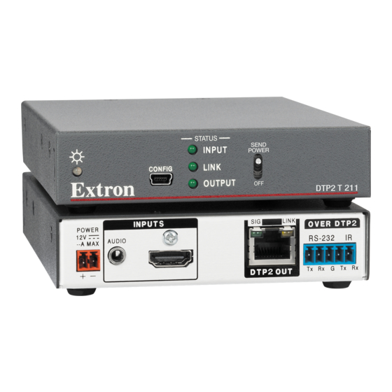
- Page 1 User Guide DTP Systems DTP2 T/R 211 HDMI Twisted Pair Transmitters and Receivers 68‑2938‑01 Rev. A 07 19...
- Page 2 Safety Instructions Safety Instructions • English Istruzioni di sicurezza • Italiano AVVERTENZA: Il simbolo, , se usato sul prodotto, serve ad WARNING: This symbol, ,when used on the product, is avvertire l’utente della presenza di tensione non isolata pericolosa intended to alert the user of the presence of uninsulated dangerous all’interno del contenitore del prodotto che può...
- Page 3 ついては、 エクス トロンのウェブサイ ト より 『Extron Safety www.extron.com and Regulatory Compliance Guide』 (P/N 68‑290‑01) をご覧ください。 Copyright © 2019 Extron Electronics. All rights reserved. Trademarks All trademarks mentioned in this guide are the properties of their respective owners. The following registered trademarks ( ®...
- Page 4 FCC Class A Notice This equipment has been tested and found to comply with the limits for a Class A digital device, pursuant to part 15 of the FCC rules. The Class A limits provide reasonable protection against harmful interference when the equipment is operated in a commercial environment.
- Page 5 Conventions Used in this Guide Notifications The following notifications are used in this guide: CAUTION: Risk of minor personal injury. ATTENTION : Risque de blessure mineure. ATTENTION: • Risk of property damage. • Risque de dommages matériels. NOTE: A note draws attention to important information. Software Commands Commands are written in the fonts shown here: ^AR Merge Scene,,Op1 scene 1,1 ^B 51 ^W^C...
-
Page 7: Table Of Contents
Contents Introduction ..........1 Remote Control ......... 20 About this Guide ..........1 Introduction to SIS ..........20 Error Messages ..........20 About the DTP2 211 Transmitter and Receiver ..1 Control Communications ......... 1 Timeout ............20 TP Cable Advantages ........2 Symbols Used in this Guide ....... - Page 8 DTP2 T/R 211 • Table of Contents viii...
-
Page 9: Introduction
Introduction • About this Guide About the DTP2 211 Transmitter and Receiver • • Application Diagram • Features About this Guide This guide describes the Extron DTP2 211 long distance High Definition Multimedia Interface (HDMI) Twisted Pair Extenders, which consists of a transmitter and receiver: •... -
Page 10: Tp Cable Advantages
POWER POWER OVER DTP + AUDIO AUDIO AUDIO --A MAX --A MAX 0.7A MAX RS-323 RS-232 DTP2 T 211 DTP2 R 211 DTP + IN DTP + OUT Transmitter Receiver DTP IN Tx Rx Tx Rx Tx Rx Tx Rx... - Page 11 DTP. The DTP2 T 211 can be set to pass the embedded digital audio, embed the analog audio, or to automatically embed the analog audio when no digital audio is detected.
- Page 12 Compatible with CATx shielded twisted pair cable — The DTP2 R 211 and • DTP2 T 211 fully support a maximum transmission distance of 330 feet (100 meters) for all compatible resolutions when used with CATx shielded twisted pair cable. Shielded twisted pair cabling with solid center conductor sizes of 24 AWG or better is recommended for optimal performance.
-
Page 13: Installation And Operation
Installation and Operation This section describes the installation and the operation of the DTP2 211 transmitter and receiver, including: • Installation Overview • Connections • Operations Installation Overview To install and set up the DTP2 211 transmitter and receiver: Turn off all equipment and disconnect it from the power source. Mount the transmitter and receiver (optional) on a rack shelf or furniture (see Mounting the Transmitter or Receiver on page 31). -
Page 14: Connections
In a DTP2 transmitter to DTP2 receiver configuration, set the SEND POWER toggle switch to the position on the powered DTP2 device to enable sending remote power to the far end DTP2 device. Set the toggle switch to the position on DOWN the DTP2 device receiving power (see figure 8, on page 15). - Page 15 Audio input (Optional)— (see figure 2 on the previous page) Plug an analog audio input into the transmitter via this female 3.5 mm TRS stereo connector (see Analog Audio Embedding (Transmitter) on page 19). NOTE: The analog audio input is in addition to the digital audio that may be embedded in the HDMI Tip (+) input (see the figure at right to identify the connector...
-
Page 16: Receiver Rear Panel Connections
Receiver Rear Panel Connections Power inlet LINK OUTPUTS OVER DTP2 POWER AUDIO Over DTP2 RS-232 and IR port 0.8A MAX RS-232 DTP2 In RJ-45 port Tx Rx Tx Rx DTP2 IN HDMI output Audio configuration toggle switch Audio output Figure 3. DTP2 211 Receiver Connectors Power inlet —... - Page 17 Set the toggle switch to the position for the analog input from the TRS audio • DOWN port on the Tx unit to be transported simultaneously with the digital embedded HDMI audio and output on the captive screw output (see figure 3, page 8) (see HDMI Audio De-embedding (Receiver) on page 19).
-
Page 18: Securing The Hdmi Connector
Securing the HDMI Connector Follow these instructions to secure the input and output connectors to the transmitter and receiver with the LockIt HDMI lacing bracket provided: Plug the HDMI cable into the rear panel connection. Loosen the HDMI connection mounting screw from the rear panel enough to allow the LockIt lacing bracket to be placed over it. -
Page 19: Tp Cable Termination And Recommendations
TP Cable Termination and Recommendations The TIA/EIA T 568B wiring standard is detailed in figure 5. Use this standard to terminate TP cables with RJ-45 connectors. Side Pins: RJ-45 1 2 3 4 5 6 7 8 Connector TIA/EIA T 568 B Wire color White-orange Orange... -
Page 20: Power Supply Wiring
Power Supply Wiring A 12 VDC, 1.5 A power supply is provided with the DTP2 211 transmitter. Follow these instructions to wire the 2-pole captive screw connector to your power supply: CAUTION: Risk of minor personal injury: ATTENTION : Risque de blessure mineure : • The DC output cables must be kept separate from each other while the power supply is plugged in. - Page 21 ATTENTION: • Always use a power supply supplied and or specified by Extron. Use of an unauthorized power supply voids all regulatory compliance certification and may cause damage to the supply and the end product. Utilisez toujours une source d’alimentation fournie ou recommandée par Extron. •...
-
Page 22: Rs-232 And Ir Connector Wiring
RS‑232 and IR Connector Wiring See figure 7 to wire the 5-pole RS-232 and IR communication connector. IR Device RS-232 Device Figure 7. RS-232 Connector Wiring Use a female 9-pin D connector to bare wire RS-232 cable or a universal control cable (UC50’... -
Page 23: Operations
Operations Front Panel Features DTP2 T 211 Front Panel DTP2 R 211 Front Panel STATUS STATUS SEND SEND INPUT INPUT POWER POWER LINK LINK CONFIG CONFIG OUTPUT OUTPUT DTP2 T 211 DTP2 R 211 Figure 8. Front Panels of the DTP2 211 Transmitter and Receiver —... - Page 24 DTP2 R 211 CATx Cable up to 330' (100 m) Local Local Power Supply Power Supply SEND POWER Extron Extron DTP2 T 211 DTP HDMI 4K 330 Rx Transmitter Receiver No Remote Power STATUS SEND OVER DTP INPUT POWER RS-232...
-
Page 25: Connecting To The Front Panel Usb Port
LINK CONFIG OUTPUT DTP2 T 211 DTP2 T 211 Transmitter DTP2 T 211 T Figure 10. Connecting a PC to the DTP2 T 211 Front Panel USB Port If this is the first time the DTP2 211 has been connected to the PC, the Found New opens (see figure 11). -
Page 26: Resetting
Select (see figure 11, on the • Yes, now and every time I connect a device previous page) if you want the computer to automatically connect to Windows Update to search the web every time the transmitter or receiver is connected to this USB port. -
Page 27: Analog Audio Embedding (Transmitter)
Analog Audio Embedding (Transmitter) Analog audio on the 3.5 mm input on the transmitter functions in two modes, which can be configured via SIS commands (see Audio Input Configuration (Tx only) on page 22): • Analog audio over DTP — Standard analog audio over DTP is digitized and transported simultaneously with the embedded digital audio on the HDMI signal. -
Page 28: Remote Control
), which signals the end of the response character string. When the transmitter or receiver is first switched on, it sends the message: (c) Copyright 2019, Extron Electronics DTP2 T/R 211, Vx.xx 60‑xxxx‑xx is the firmware version number. • Vx.xx •... -
Page 29: Symbols Used In This Guide
Symbols Used in this Guide When programming in the field, certain characters are most conveniently represented by their hexadecimal rather than their ASCII values. The table below shows the hexadecimal equivalent of each ASCII character: ASCII to Hex Conversion Table Space •... -
Page 30: Command And Response Table For Sis Commands
Command and Response Table for SIS Commands Command ASCII Command Response Additional Description (host to unit) (unit to host) Audio Input Configuration (Tx only) Set audio input format = default. AFMT AfmtI View audio input format IAFMT AfmtI Verbose mode 2/3 KEY: = Audio input 0 = Auto (default);... - Page 31 Command ASCII Command Response Additional Description (host to unit) (unit to host) Unit Name Set unit name E X# • Set unit name to factory • • DTP2‑T‑211 default • DTP2‑R‑211 Query unit name • Verbose mode 2/3 KEY: Text string of up to 24 characters (Default = DTP2‑T‑211 or DTP2‑R‑211).
-
Page 32: Downloading And Updating Firmware
Downloading and Updating Firmware Firmware for the DTP2 211 products can be upgraded using Extron Firmware Loader and a PC. Both Extron Firmware Loader and upgraded firmware for the DTP2 211 can be downloaded at www.extron.com. NOTE: Upgrading the firmware does not overwrite the current configuration. Downloading Extron Firmware Loader On the Extron website, mouse over the tab (see figure 14,... -
Page 33: Installing Firmware Loader
Figure 16. Firmware Loader Software Click (see figure 16, ) to see the issues that have been addressed by Release Notes the latest update. Click the link on the right ( ). Note where the file is saved. Download Installing Firmware Loader Once has been downloaded, run the file from the save... -
Page 34: Updating Firmware On A Dtp2 211 Device
Open the Firmware Loader via the Firmware Loader icon installed during the download (optional) or your desktop menu by making the following Start selections: Start > All Programs > Extron Electronics > Firmware Loader > Firmware Loader window opens. The window opens in front (see Firmware Loader Add Device... - Page 35 (see figure 20, ). If the connection is successful, the unit name is Connect displayed in green in the section, followed by a check mark ( Connected Device DTP2 T 211 DTP2 T 211 DTP2T211\dtp2t211_A_v1.00_081518.S19 Figure 20. Add Device Window Click the...
- Page 36 On the window, the path to the new firmware file is displayed in the Add Device... field (see figure 22, Path DTP2 T 211 DTP2 T 211 DTP2T211\dtp2t211_A_v1.00_081518.S19 Figure 22. Path to New Firmware File on the Add Device Window If this is the only device uploading firmware, click ).
- Page 37 Extron USB Devi... Connected Figure 23. Firmware Loader Screen with a DTP2 T 211 Added To remove a device from the section, do the following: Device Click on the names of the devices to be deleted, highlight them (see figure 23, Click on the tab (see figure 24,...
- Page 38 DTP2 T 211 60-1631-52 1.00.001 dtp2t211_A_v1.00.00... Extron USB Devi... Uploading... Connected Figure 25. Firmware Upload in Progress The upload is complete when the field shows , (see Remaining Time 00.00.00 figure 26, ) the column shows ), and is displayed Progress...
-
Page 39: Reference Information
Reference Information This section provides procedures for mounting the DTP2 211 transmitter and receiver and disconnecting the ground between them. • Mounting the Transmitter or Receiver • Internal Settings Mounting the Transmitter or Receiver ATTENTION: Risk of property damage: ATTENTION : Risque de dommages matériels : •... -
Page 40: Ul Rack-Mounting Guidelines
UL Rack‑Mounting Guidelines The following Underwriters Laboratories (UL) requirements pertain to the installation of the unit into a rack. • Elevated operating ambient temperature — If installed in a closed or multi-unit rack assembly, the operating ambient temperature of the rack environment may be greater than room ambient. - Page 41 NOTES: • If the ground jumper is Open, a DTP2 211 unit cannot remotely power the other unit, because of ground potential differences. Each unit requires a local power supply. If the 48 VDC remote power jumper is Off, DTP2 211 unit cannot remotely power •...
- Page 42 ATTENTION: • If not provided with a power supply, this product is intended to be supplied by a UL Listed power source marked “Class 2” or “LPS,” rated 12 VDC, 1.5 A minimum. • Si le produit n’est pas fourni avec une source d’alimentation, il doit être alimenté...
- Page 43 Extron Electronics makes no further warranties either expressed or implied with respect to the product and its quality, performance, merchantability, or fitness for any particular use. In no event will Extron Electronics be liable for direct, indirect, or consequential damages resulting from any defect in this product even if Extron Electronics has been advised of such damage.